

Remember the SparkFun Electronics (SFE) I2C Qwiic Adapter project that we built in the May 2019 issue of ODROID Magazine? Oh, you don’t recall reading that article? Okay, I’ll wait here while you go back and refresh your recollection. Now that you’re all up to speed on the Qwiic Adapter article, here’s another Qwiic project that will give your ODROID-GO the gift of infrared (IR) vision.
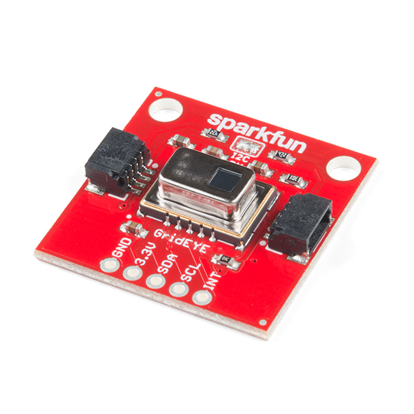
This particular type of IR vision is supplied by a Panasonic AMG8833 IR array sensor (see Figure 1). Inside this sensor is an 8x8 thermopile “grid” array. What exactly is a thermopile? Well, it’s a fancy word for a pile of thermos. No, seriously, a thermopile is a device housing a series of thermocouples, each of which measures temperature via a pair of dissimilar metal wires. In turn, these wires measure the difference in potential that is created at the wires’ junction. Whew! You know what? I like the ‘pile of thermos’ definition better.
Granted, an 8x8 visual array is very low resolution, but objects placed 200-300mm in front of the Panasonic sensor can provide a colorful visual treat on the ODROID-GO LCD. By adding the Grid-EYE to the Qwiic system, SFE have made IR vision a simple plug-and-go project for the ODROID-GO.
Step-by-Step
1. Insert the Qwiic Adapter for ODROID-GO PCB into the general purpose input/output (GPIO) female header located along the top edge of the ODROID-GO. If you don’t already have this adapter PCB, you can learn how to make one in the May 2019 issue of ODROID Magazine.
2. Plug a Qwiic cable (e.g., 100 mm; SFE PRT-14427) into the Qwiic adaptor board.
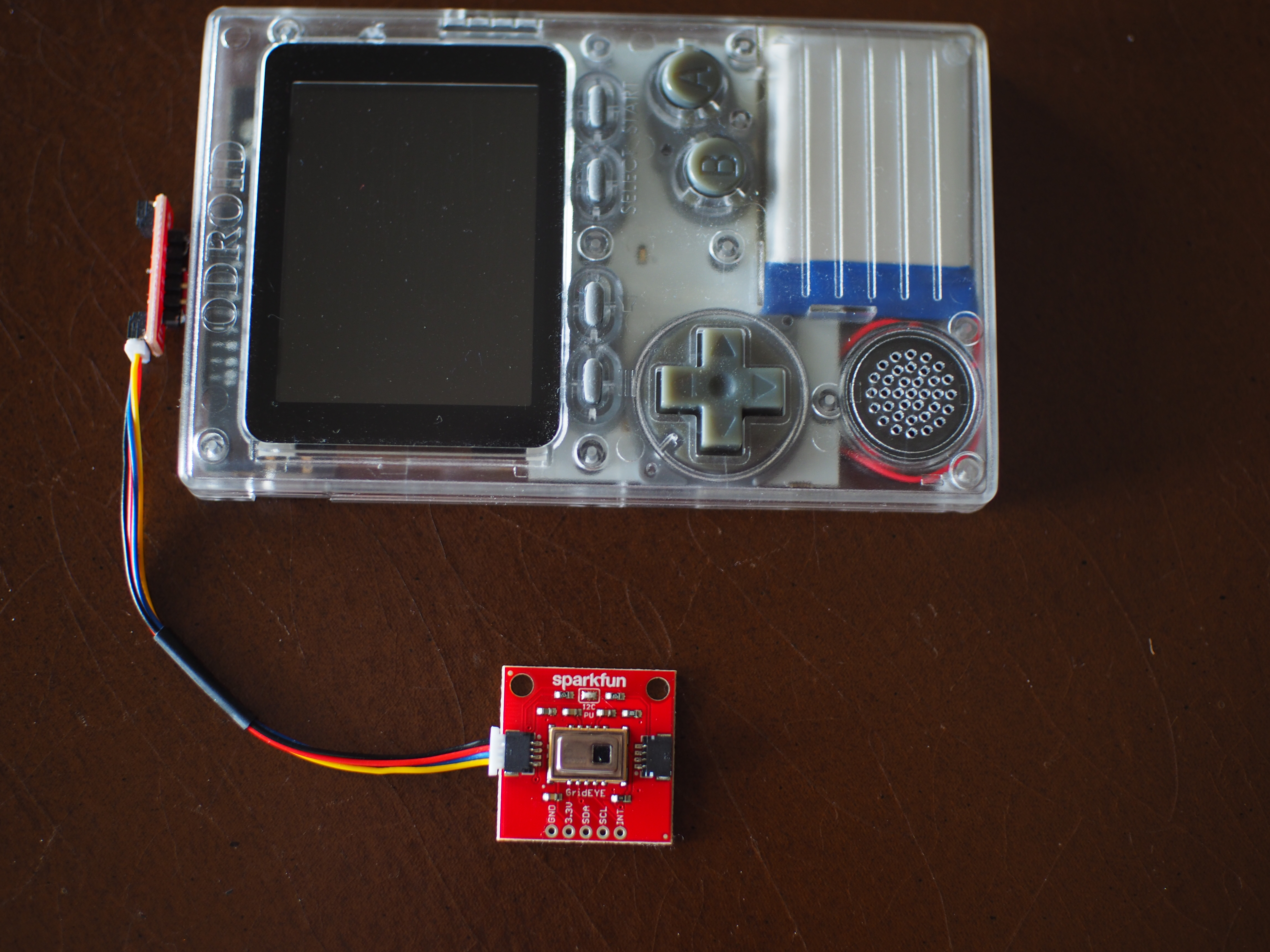
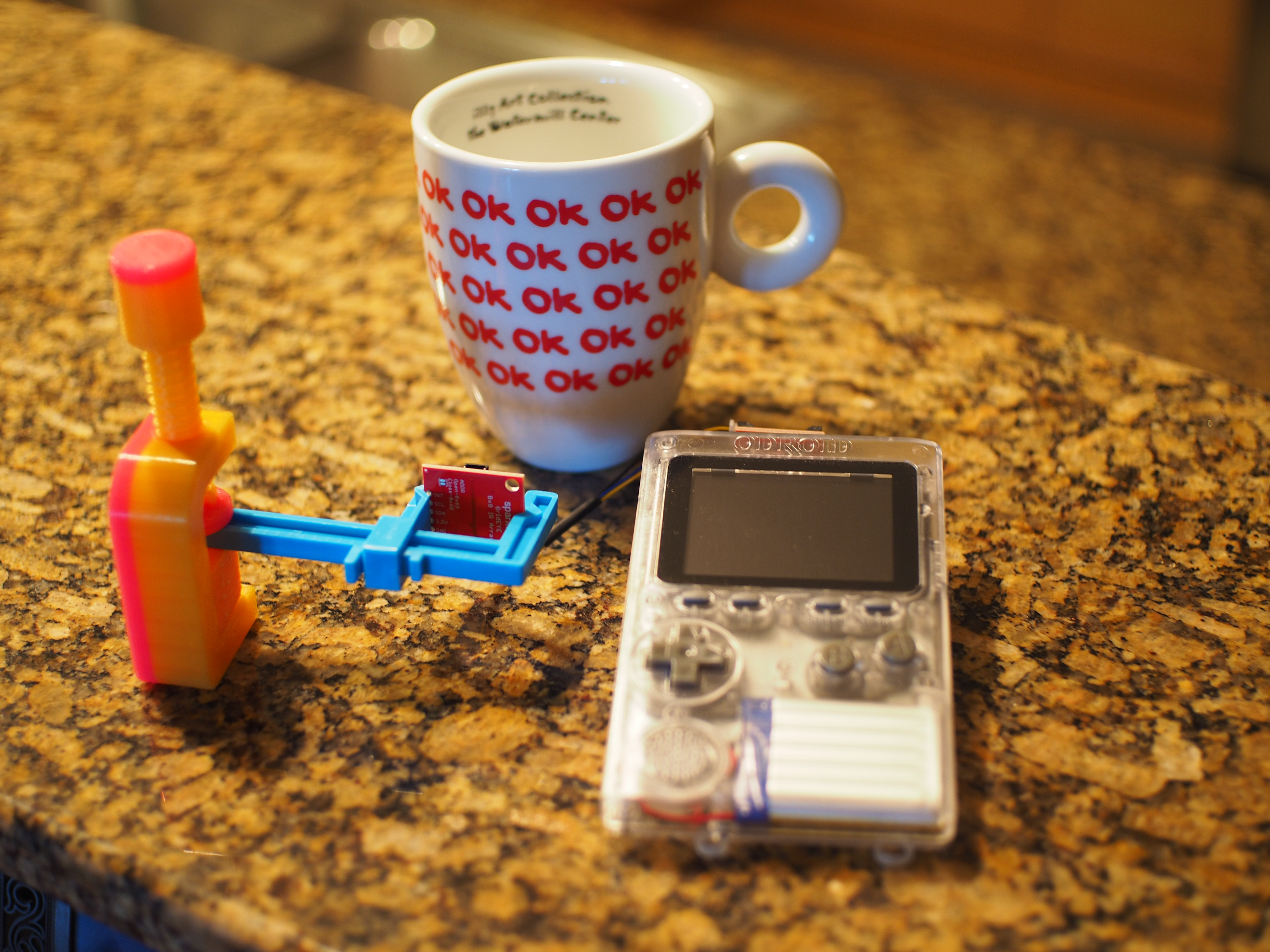
3. Attach the SparkFun Grid-EYE infrared array breakout – AMG8833 (Qwiic) (SFE SEN-14607) into the other end of the cable. An ODROID-GO is ready to Qwiic-ly scan for heat signatures in Figure 2.
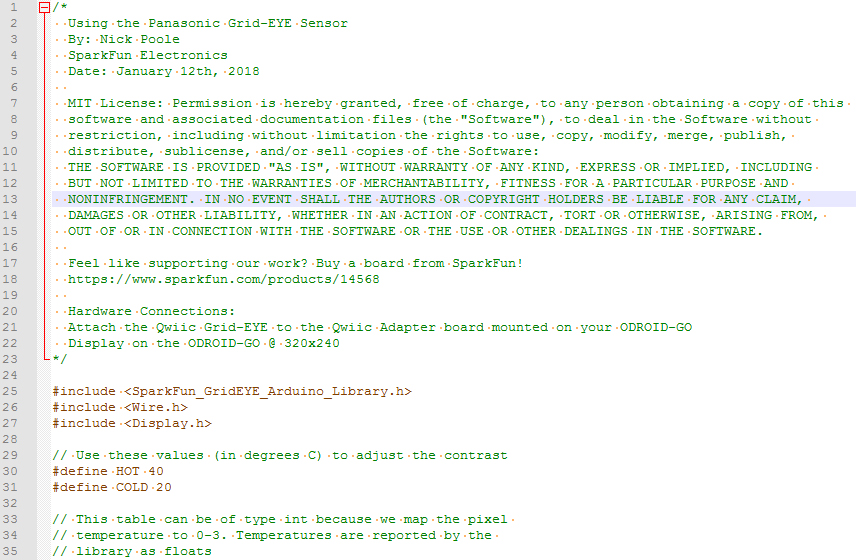
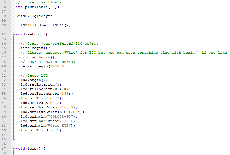
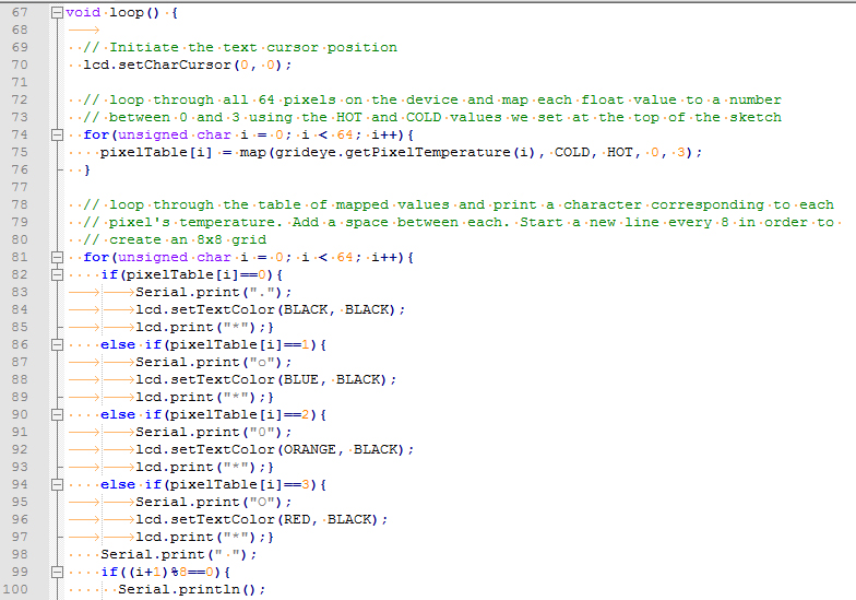
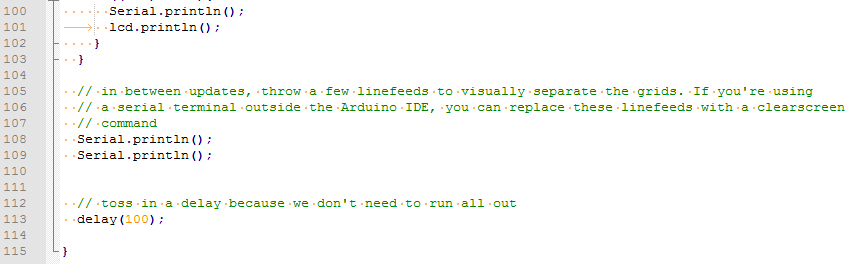
4. Enter this super-short Arduino sketch (refer to Figure 3 – Figure 3c) into the Arduino Integrated Development Environment (IDE) and compile/load the sketch onto your ODROID-GO. Remember to create your own Display.h library subset (as described in the Qwiic Adapter project) from the ODROID-GO Master Library. Otherwise, the sketch will not compile inside the Arduino IDE.
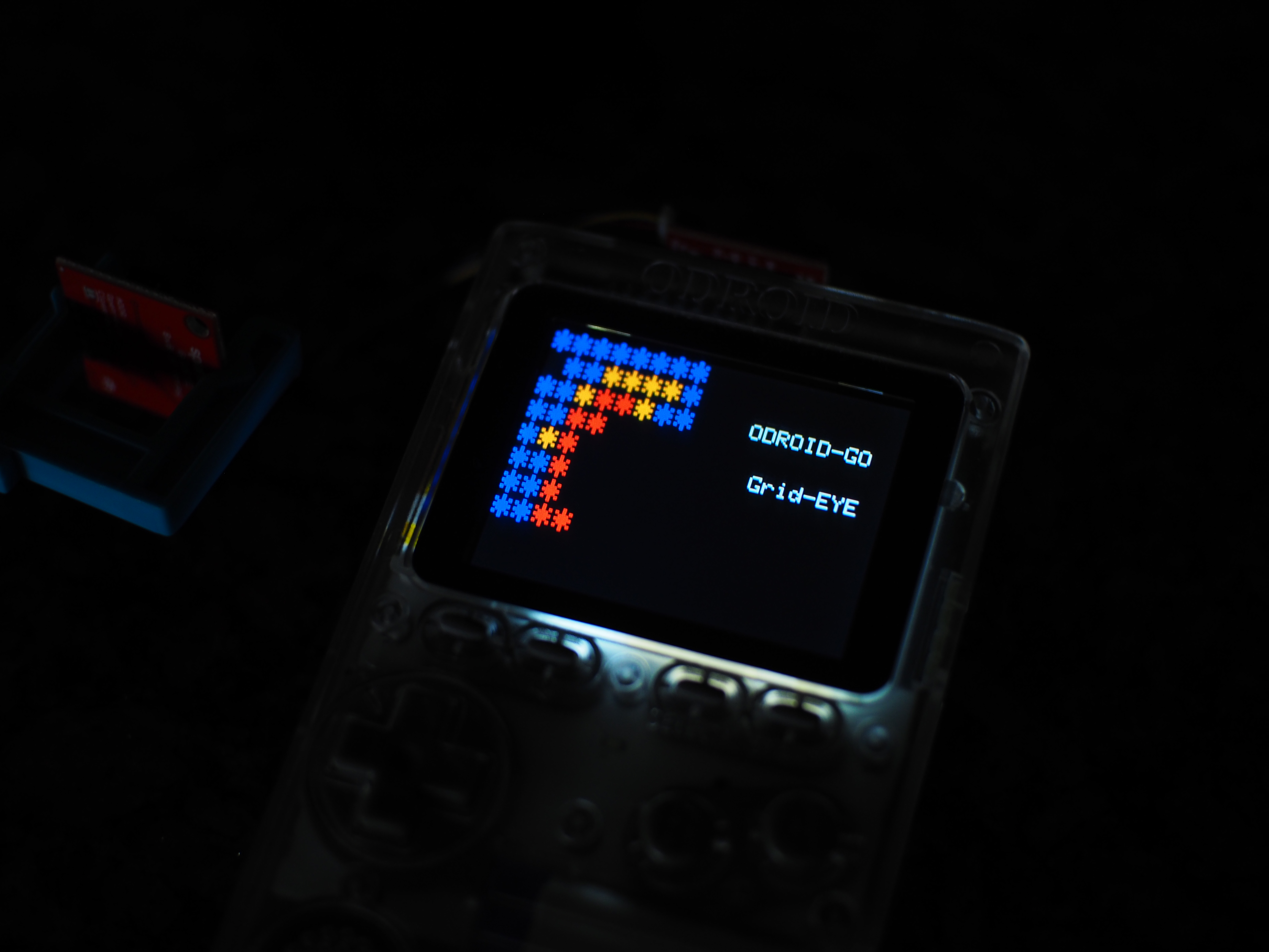
Disconnect the ODROID-GO, turn it on, and go look for some hot stuff to measure. A hot mug of coffee is an ideal test subject (see Figure 4). Your new IR vision on the ODROID-GO is now ready to show you things in your life that are too hot to handle (see Figure 5).
Be the first to comment