
There it is; sitting right on top of your ODROID-GO handheld, staring you in the face - a 10-pin general purpose input/output (GPIO) female header port. How do we go about using it? Well, you can plug in some sensors (e.g., ODROID Weather2 Board), write a short Arduino sketch, and use the on-board liquid crystal display (LCD) for monitoring the data stream.
You may ask, “Tell me something, I don’t already know!”. Well, how about this? For just a paltry $1.50 investment, you can open up an entire ecosystem of sensors, tools, actuators, and displays for your ODROID-GO AND you will still have four GPIO pins left over for other projects (see Figure 1).
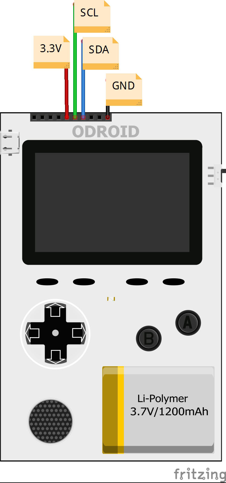
Before we begin following the dead-simple step-by-step instructions for this horizon-expanding project, let me make one “Qwiic” point. You see, this project is going to utilize the inter-integrated circuit (I2C; pronounced “eye-squared see”) interface that can be accessed via four pins on the ODROID-GO GPIO interface. The pins that we will be using are 3.3V, SCL, SDA, and GND, i.e., pins number 6, 5, 4, and 1, respectively. That is all there is to it, these four pins represent the GO’s I2C interface.
As you can see, only four pins are needed for using an I2C interface. However, do not let this tiny pin count fool you. These four wires can support up to 1008 devices. Up until now, accessing that many devices would have been a royal pain in your chair cushion. Luckily, we have a I2C savior. SparkFun Electronics (SFE) recently made a “Qwiic” decision that will pay big dividends to the ODROID-GO.
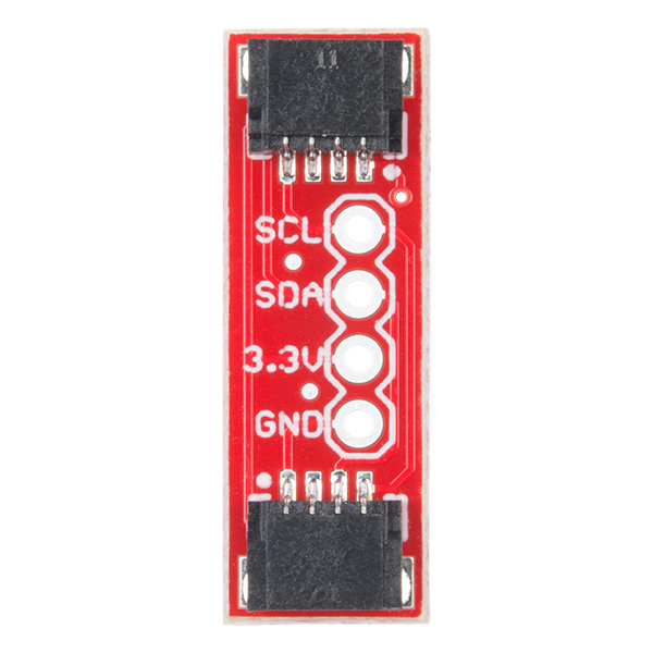
In a response to building a “simple” plug-and-go interface for complex microcontroller or microprocessor-friendly breakout boards, SFE devised the Qwiic system. Simply put, Qwiic is a four-pin plug/receptacle combination that adds an I2C interface to, well, anything. You can find Qwiic plugs on environmental sensors, laser time-of-flight distance tools, flexible actuators, and Arduino clones. Unfortunately, adding your legacy breakout boards to the Qwiic system was still a rat’s nest mess of twisted cables. That is until the Qwiic Adapter arrived (see Figure 2). This small, inexpensive sliver of a board enables virtually any I2C legacy device to be incorporated into the Qwiic fold. That means the ODROID-GO can be quickly and easily upgraded to the Qwiic system.
Now are you ready to add an entire universe of I2C breakout boards to your GO? Well, then, let us be Qwiic about it. Oh, and if you are curious about the definition of “Qwiic,” do not worry, there is none. However, you can safely piece together this approximation: “Quickly, wired inter-integrated circuit”.
Parts
- SFE Qwiic Adapter – DEV-14495
- 6-pin male header (you can use the 10-pin male header that is included with your ODROID-GO kit) or, SFE PRT-00116
- Qwiic Cable 100mm – SFE PRT-14427
- 2x Short lengths of scrap solid-core wire
Step-by-Step
Step 1. Break off a 6-pin length of headers from your stock male header.
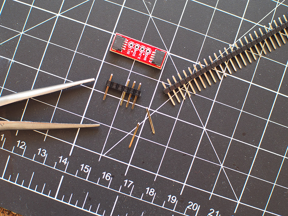
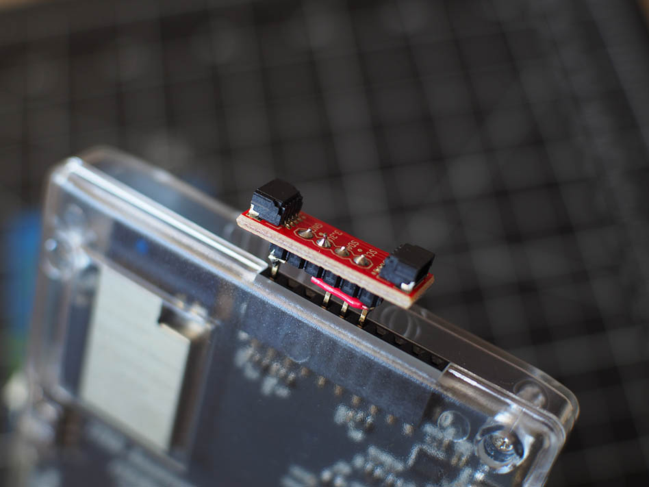
Step 2. Use a pliers for removing two pins (i.e., #2 & #3) from the 6-pin header as shown in Figure 3. Yes, at this point you can begin counting your pins from either end of the header.
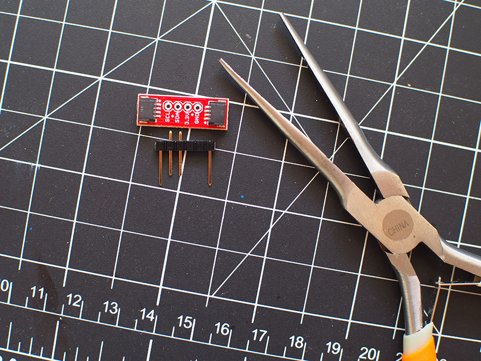
Step 3. Gently push the two outside pins down until each pin’s top is flush with the top of the header (see Figure 4).
Step 4. Lay the Qwiic Adapter board on top of the header and carefully push pins #4 (i.e., SDA) and #5 (i.e., SCL) up until each pin top is flush with the top of the adapter PCB.
Step 5. Solder the pins to the SCL and SDA pads on the Qwiic Adapter PCB.
NOTE: the remaining steps will require some precision wiring and careful soldering—but I’ve got confidence in you and I KNOW that you can do it.
Step 6. Cut your scrap wire to a length of about 7-9mm and push this wire down through the GND pad on the adapter PCB. Continue through the header opening that is directly underneath the GND pad. Now bend the wire towards the closest extended header pin - not toward the SDA pin; go the opposite direction.
Step 7. Solder one end of this wire to the GND pad and the other end to the extended header pin. When completely assembled and installed on the ODROID-GO, this pin will go into GPIO pin #1.
Step 8. Cut a remaining piece of scrap wire to a 12-15mm length and insert this wire into the 3.3V pad on the Qwiic Adapter PCB. Continue pushing this wire down into the header opening that is underneath this pad. Bend the wire and route it along the header to the remaining extended pin located furthest outboard of the male header.
Step 9. Be absolutely certain that this wire does not make contact with any other header pins. Use a scrap piece of wire insulation to ensure isolation from the SCL and SDA header pins.
Step 10. Solder this wire to the 3.3V PCB pad and the other end to the extended header pin. This pin will go into GPIO pin #6 (see Figure 5).
There you go. You have just upped your game machine’s I2C game. Make sure to test your Qwiic pins on the adapter board before attaching a breakout board. Just plug the Qwiic Adapter into the ODROID-GO between GPIO pins 1-6; ensure pin #1 is the GND pin on the adapter. Then test the voltage output with your trusty multimeter between the 3.3V and GND pads (see Figure 6).
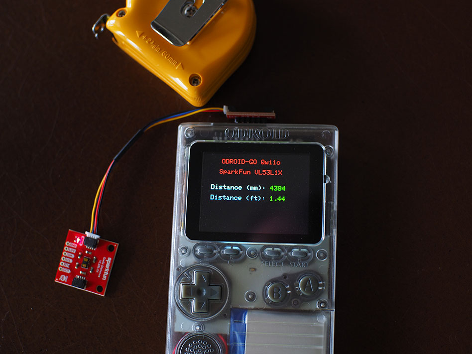
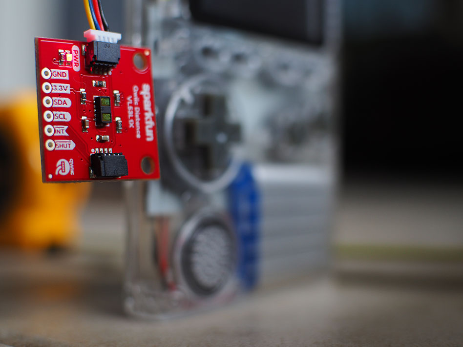
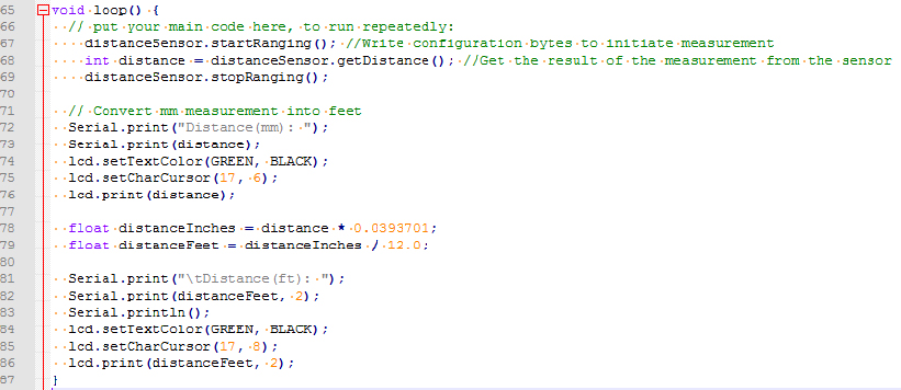
Now dip your toe into your new ecosystem with the SFE Qwiic Distance VL53L1X time-of-flight laser measure (see Figure 7). Also, look how easy it is to write code for such a complex breakout board (see Figure 8). The Qwiic system automatically recognizes and uses the ODROID-GO I2C pins. That is slick. It really is Qwiic to now plug-and-GO-have-fun.
In Conclusion
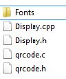
1. The ODROID-GO master library has some conflicts with the SFE software libraries. Therefore, copy the ODROID-GO header files that you need for your project and insert them into a new library directory (as shown in Figure 9).
2. Other Qwiic breakout boards can be used with your new adapter, too. Try them individually or daisy-chain a couple hundred of them together.
Be the first to comment