One of the best features of the ODROID-GO Advance is that you can build it yourself, since it comes in kit form. This means that you can learn how the pieces fit together, do it as a project with your siblings, friends, or children, and have the satisfaction of playing games on a truly unique device that you built yourself!
To assemble the ODROID-GO Advance, unpack all of the parts and verify them against Figure 1. Be gentle when attaching cables to the PCB, and make sure not to over-tighten any of the screws. Read through all of the instructions, and watch the video, before starting.
Figure 1 - ODROID-GO Advance kit annotated parts diagram
A
USB Type-A Power Cable
J
D-PAD rubber
B
Front enclosure
K
A, B, X, Y button rubber
C
Back enclosure
L
battery sticker
D
Plastic L/R trigger, X, Y, power Buttons
M
Analog joystick
E
Plastic D-pad, A, B Buttons
N
320×480 TFT LCD
F
ODROID-GO-Advance board
O
0.5W speaker
G
3000mAh battery
P
1.7×5 screws 7pcs
H
LCD window
Q
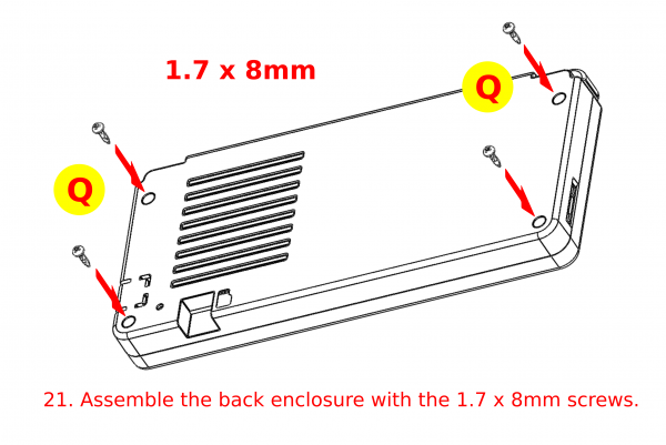
1.7×8 screws 4pcs
I
I ~ VI button rubber
R
Screw driver
Build Instructions
The video at https://youtu.be/FsfpAkKGEXc shows detailed instructions on how to use the kit, and should be used in conjunction with the instructions here to ensure that everything is assembled properly.
LCD assembly
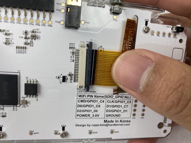
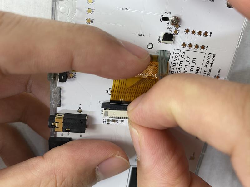
Figure 2 - Fold the yellow tab as shown
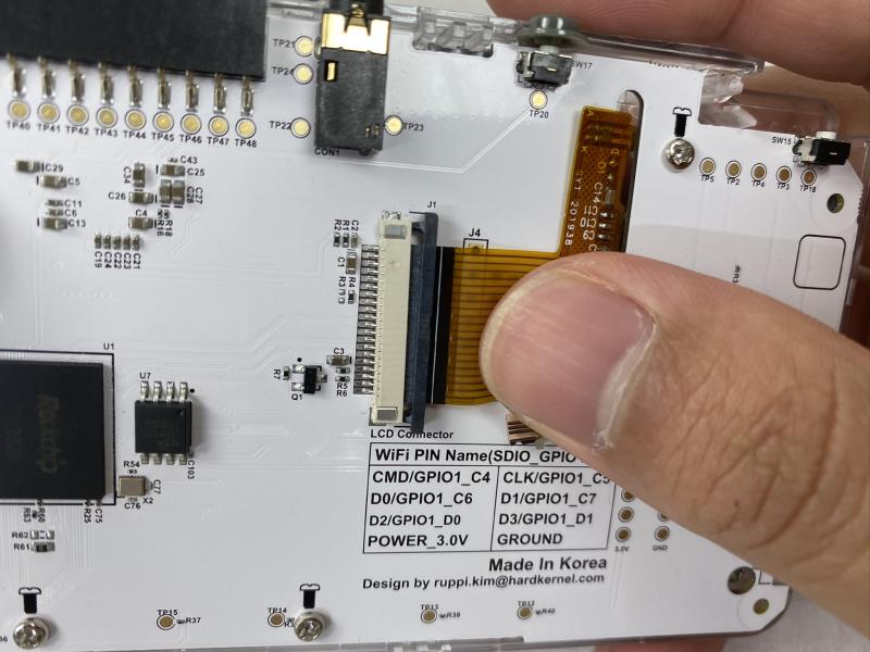
Figure 3- Closeup of LCD panel insertion
Figure 4 - Closeup of the yellow tab
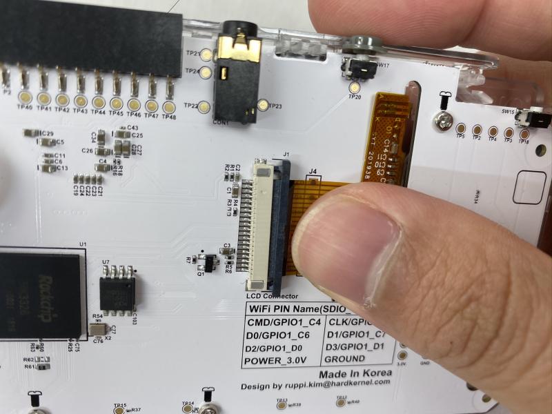
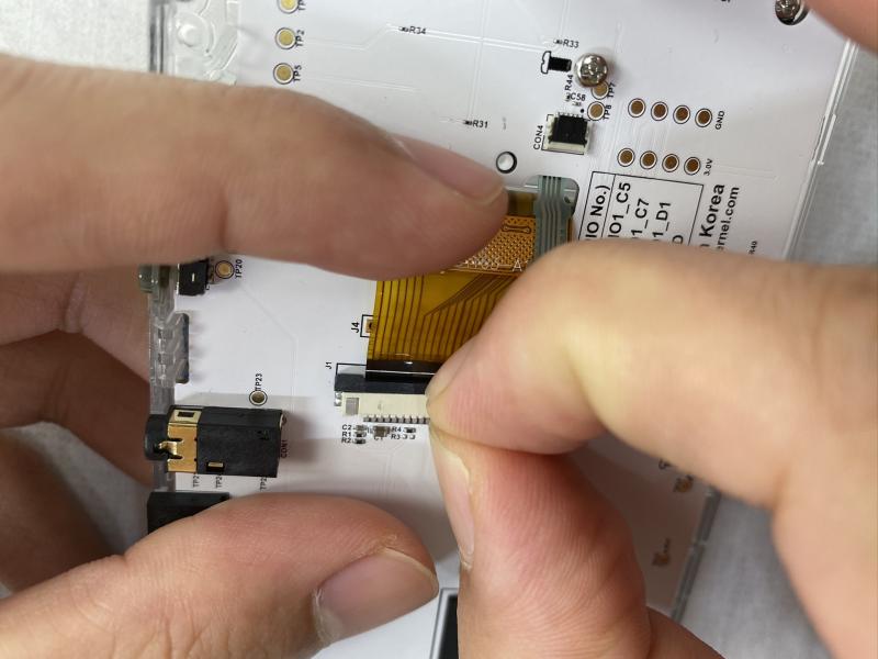
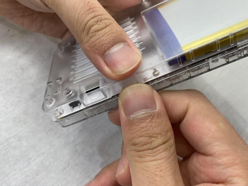
Figure 5- Insert the LCD panel as shown
Figure 6- Closeup of LCD panel insertion
Figure 7 - Closeup of LCD panel insertion
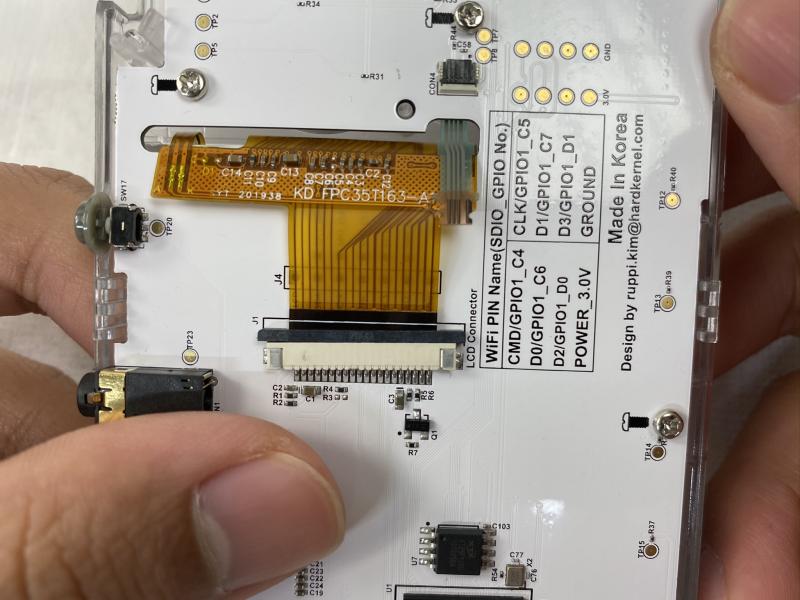
Figure 8 - Closeup of LCD panel insertion
Figure 9 - Closeup of LCD panel insertion
Figure 10 - Closeup of LCD panel insertion
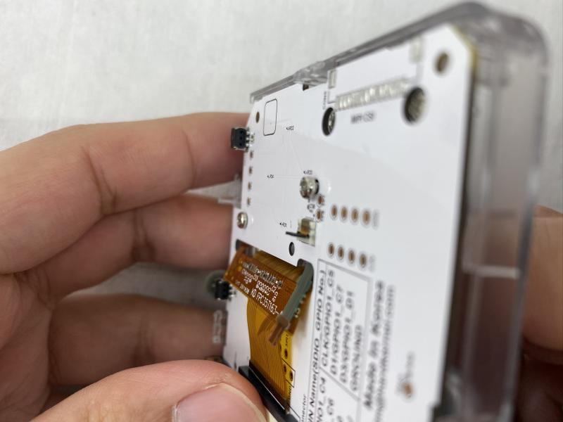
Figure 11 - Closeup of LCD panel insertion
Inserting the LCD
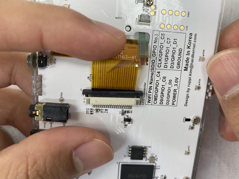
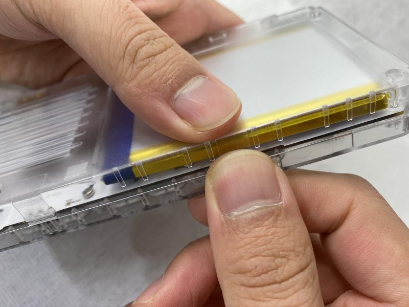
Figure 12 - Make sure that the yellow tab is in front of the enclosure
Figure 13 - Closeup of the LCD panel insertion
Figure 14 - Carefully remove the backing of the double-sided tape, remove the LCD protective cover by pulling on the yellow tab, and carefully attach the LCD protector with the exposed double-sided tape
Figure 15 - Closeup of removing the double-sided tape
Figure 16 - Closeup of removing the double-sided tape
Figure 17 - Closeup of removing the double-sided tape
Figure 18 - Closeup of removing the double-sided tape
Figure 19 - Closeup of removing the double-sided tape
Figure 20 - Closeup of removing the double-sided tape
For alternative assembly instructions for the LCD panel, check out the video at https://youtu.be/ShFrKvPcjsE.
Analog joystick assembly
Figure 21 - Assemble the analog joystick with 1.7 x 5mm screws, making sure not to over-tighten the screws
Figure 22 - Closeup of attaching the analog joystick
Figure 23 - Closeup of attaching the analog joystick
Button assembly
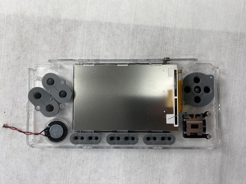
Figure 24 - Put the D-pad and buttons on the front enclosure
Figure 25 - Closeup of attaching the buttons
Figure 26 - Closeup of attaching the buttons
Figure 27 - Closeup of attaching the buttons
Figure 28 - Closeup of attaching the buttons
Figure 29 - Closeup of attaching the buttons
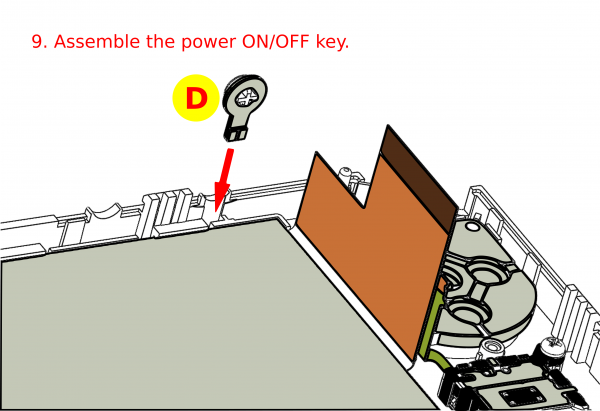
Figure 30 - Assemble the power button
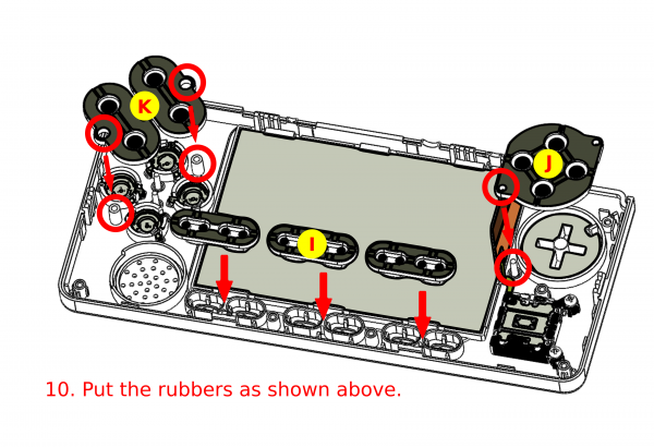
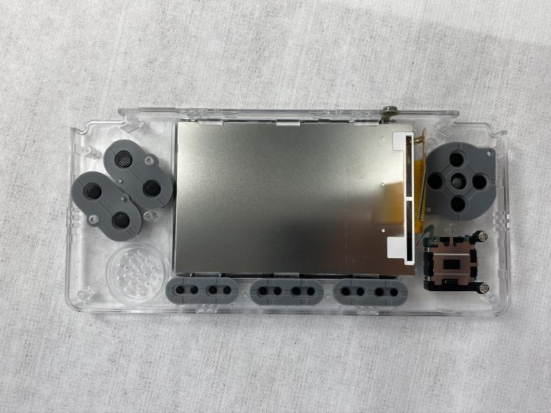
Figure 31 - Insert the rubber buttons into the enclosure
Figure 32 - Closeup of inserting the rubber buttons
Speaker assembly
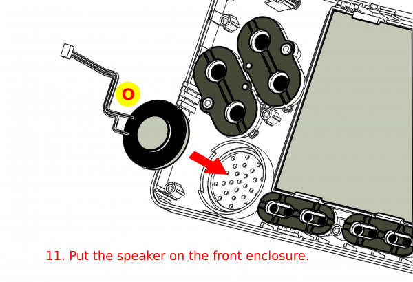
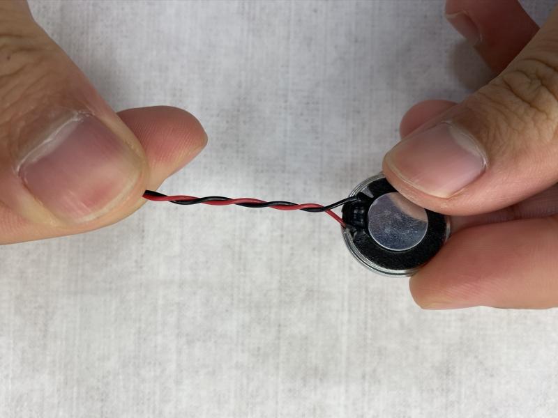
Figure 33 - Insert the speaker into the front enclosure
Figure 34 - Closeup of speaker assembly
Figure 35 - Closeup of speaker assembly
PCB board assembly
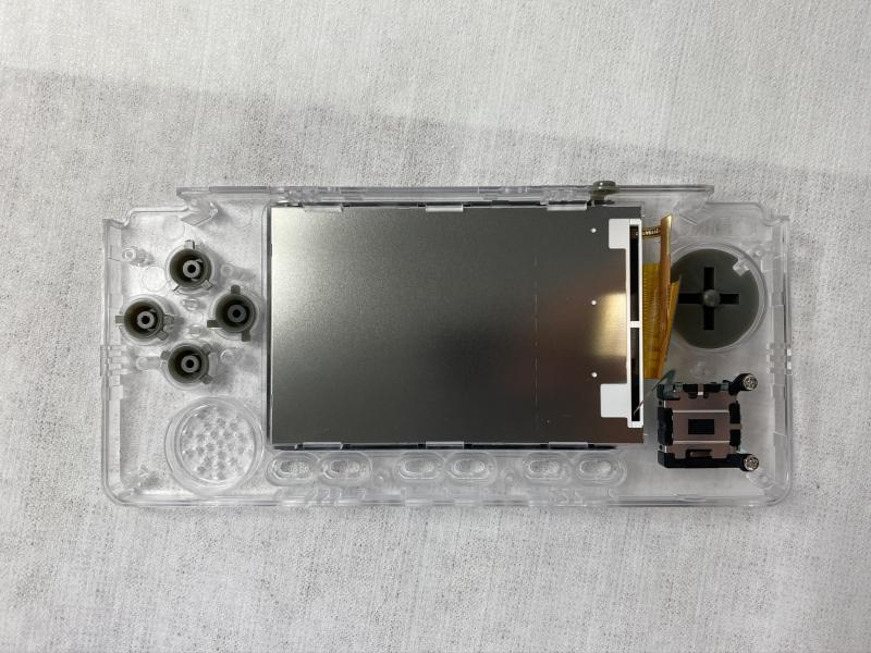
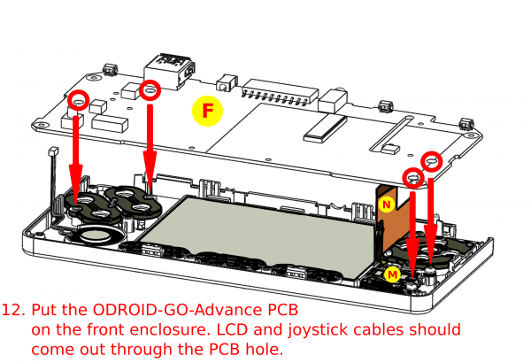
Figure 36 - Put the ODROID-GO Advance PCB in the front enclosure
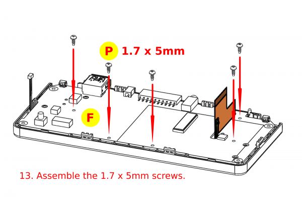
Figure 37 - Insert the 1.7 x 5mm screws
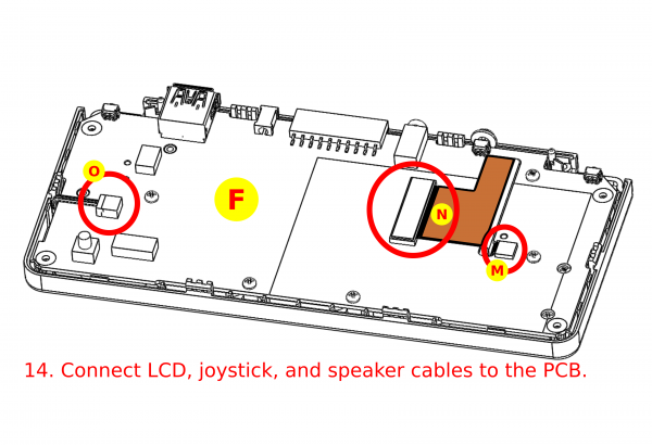
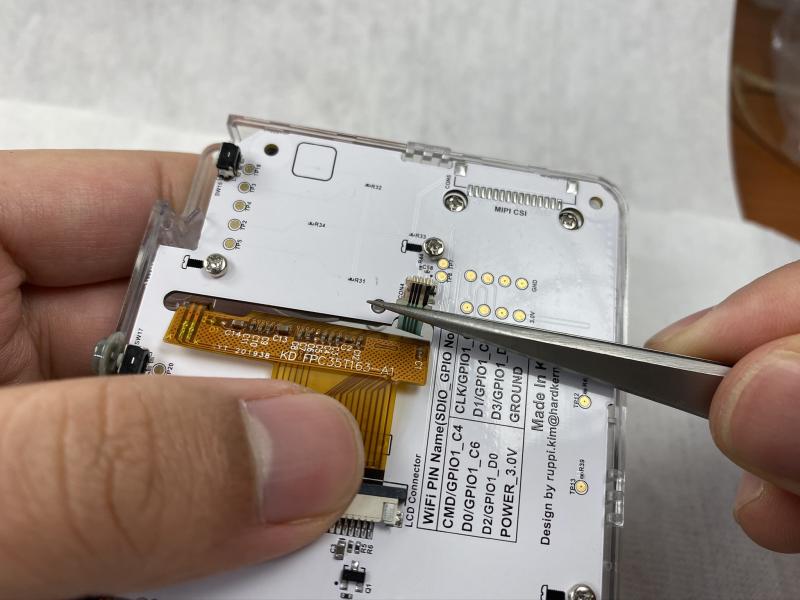
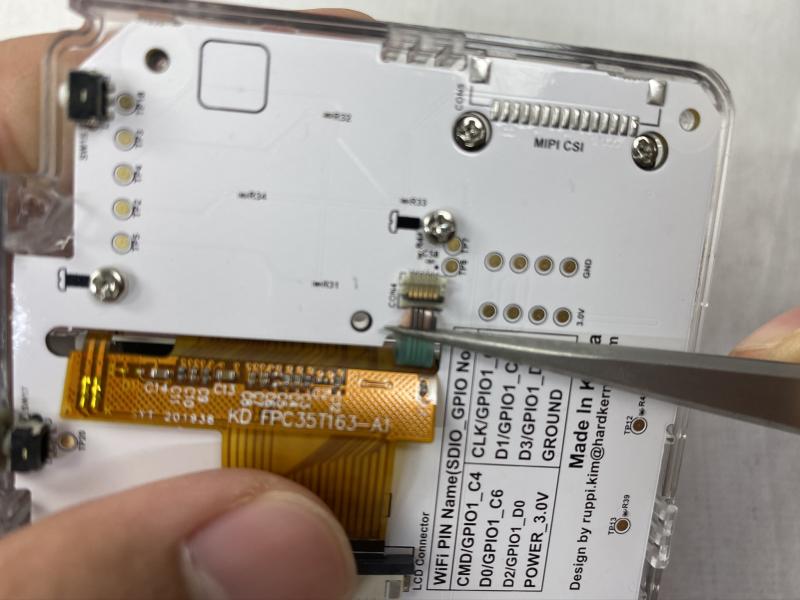
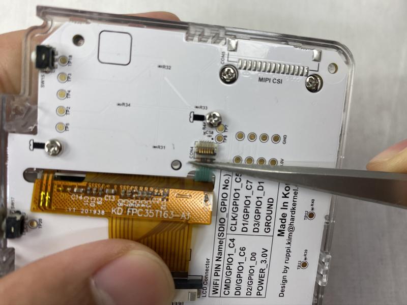
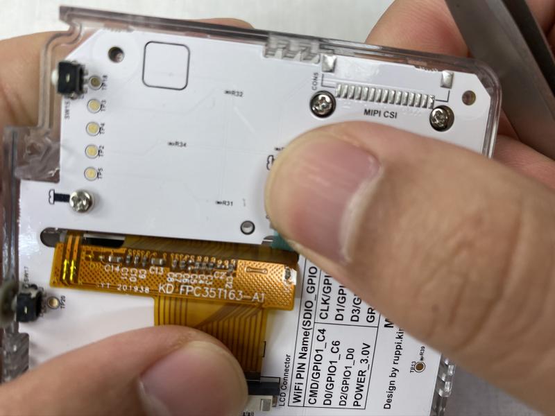
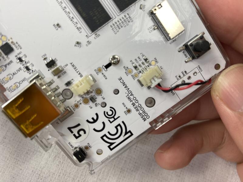
Figure 38 - Connect the LCD, joystick, and speaker cables to the PCB
Note: never raise the joystick connector more than 90 degrees or it will break.
Figure 39 - Closeup of attaching the PCB connections
Figure 40 - Closeup of attaching the PCB connections
Figure 41 - Closeup of attaching the PCB connections
Figure 42 - Closeup of attaching the PCB connections
Figure 43 - Closeup of attaching the PCB connections
Figure 44 - Closeup of attaching the PCB connections
Figure 45 - Closeup of attaching the PCB connections
Figure 46 - Closeup of attaching the PCB connections
Figure 47 - Closeup of attaching the PCB connections
Figure 48 - Closeup of attaching the PCB connections
Figure 49 - Closeup of attaching the PCB connections
Figure 50 - Closeup of attaching the PCB connections
Figure 51 - Closeup of attaching the PCB connections
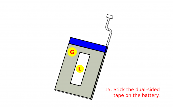
Battery assembly
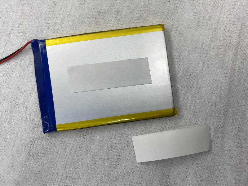
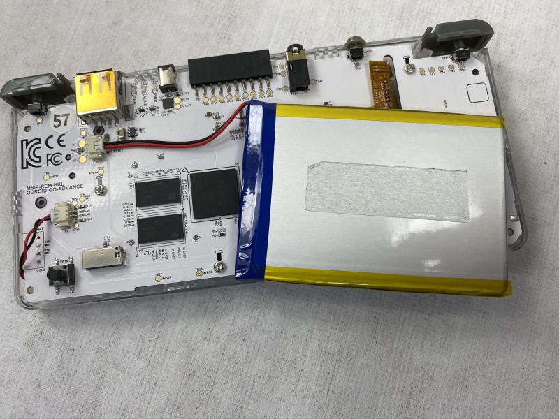
Figure 52 - Stick the dual-sided tape on the battery
Figure 53 - Close of the battery tape
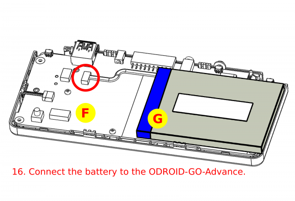
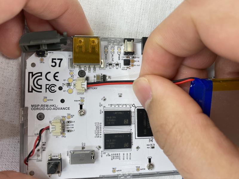
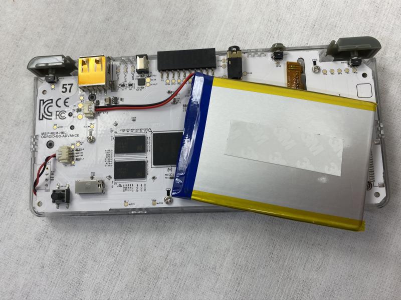
Figure 54 - Connect the battery to the ODROID-GO Advance
Figure 55 - Connect the battery to the ODROID-GO Advance
Trigger buttons assembly
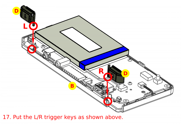
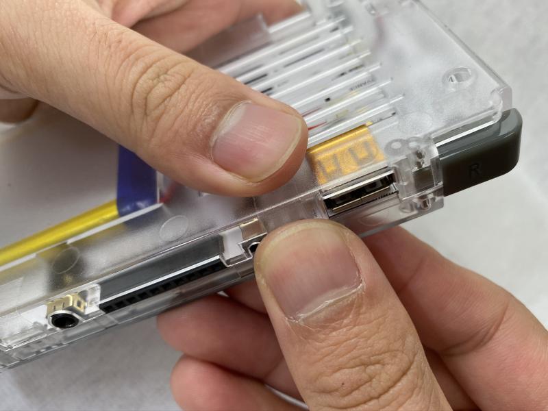
Figure 56 - Insert the trigger button keys into the slots, making sure to align them to the left and right side as indicated on the button
Figure 57 - Close of trigger button keys
Back enclosure assembly
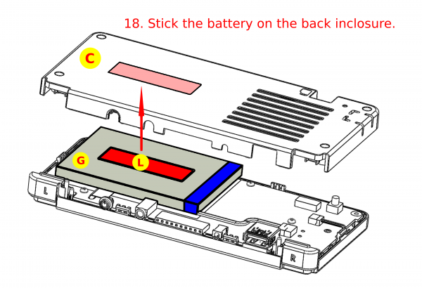
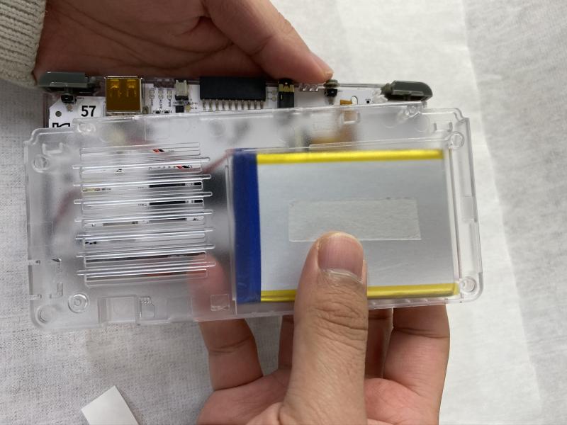
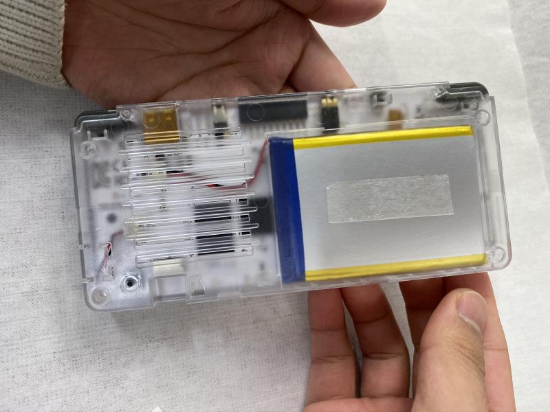
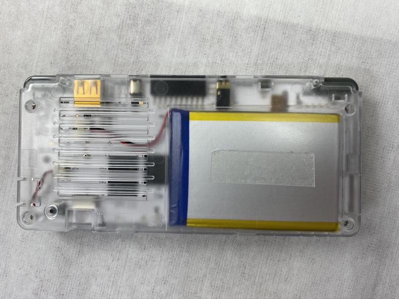
Figure 58 - Stick the battery on the back enclosure
Figure 59 - Closeup of battery attachment
Figure 60 - Closeup of battery attachment
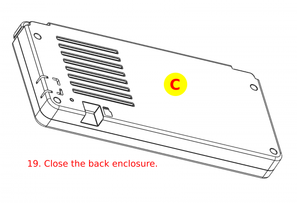
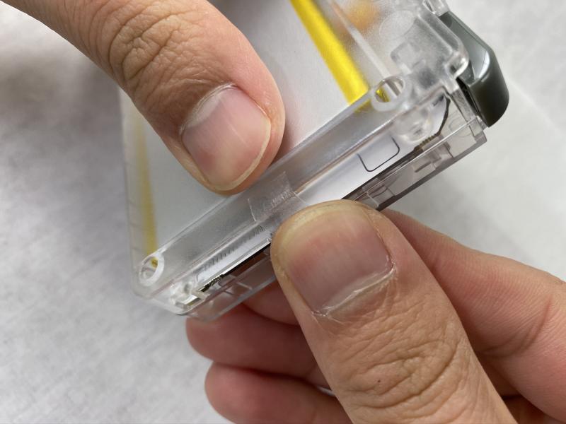
Figure 61 - Close the back enclosure
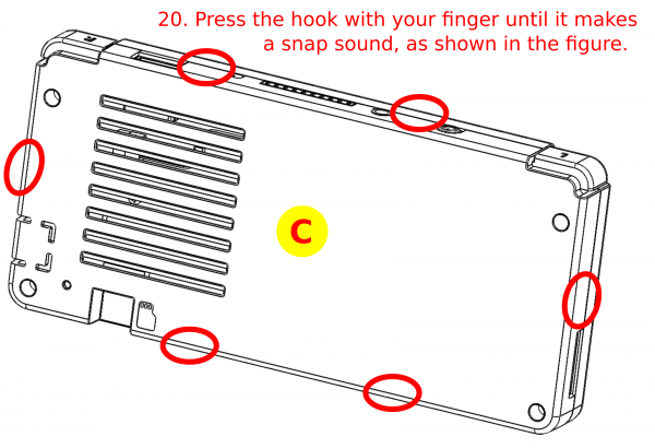
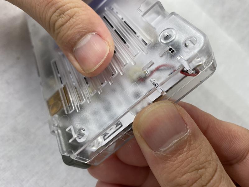
Figure 62 - Press the hook with your finger until it makes a snapping sound
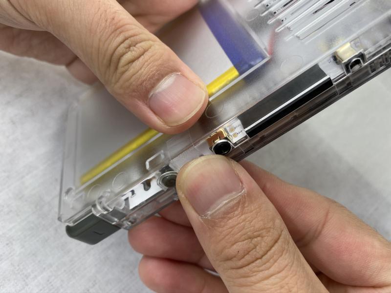
Figure 63 - Closeup of attaching the enclosure
Figure 64 - Closeup of attaching the enclosure
Figure 65 - Closeup of attaching the enclosure
Figure 66 - Closeup of attaching the enclosure
Figure 67 - Closeup of attaching the enclosure
Figure 68 - Closeup of attaching the enclosure
Figure 69 - Closeup of attaching the enclosure
Figure 70 - Assemble the back enclosure with the 1.7 x 8mm screws, being careful not to over-tighten them


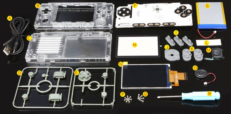
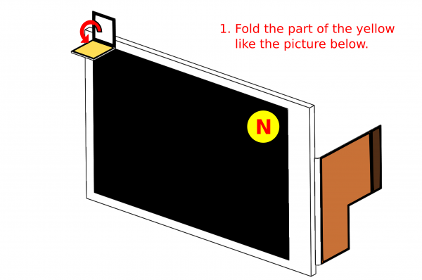 Figure 2 - Fold the yellow tab as shown
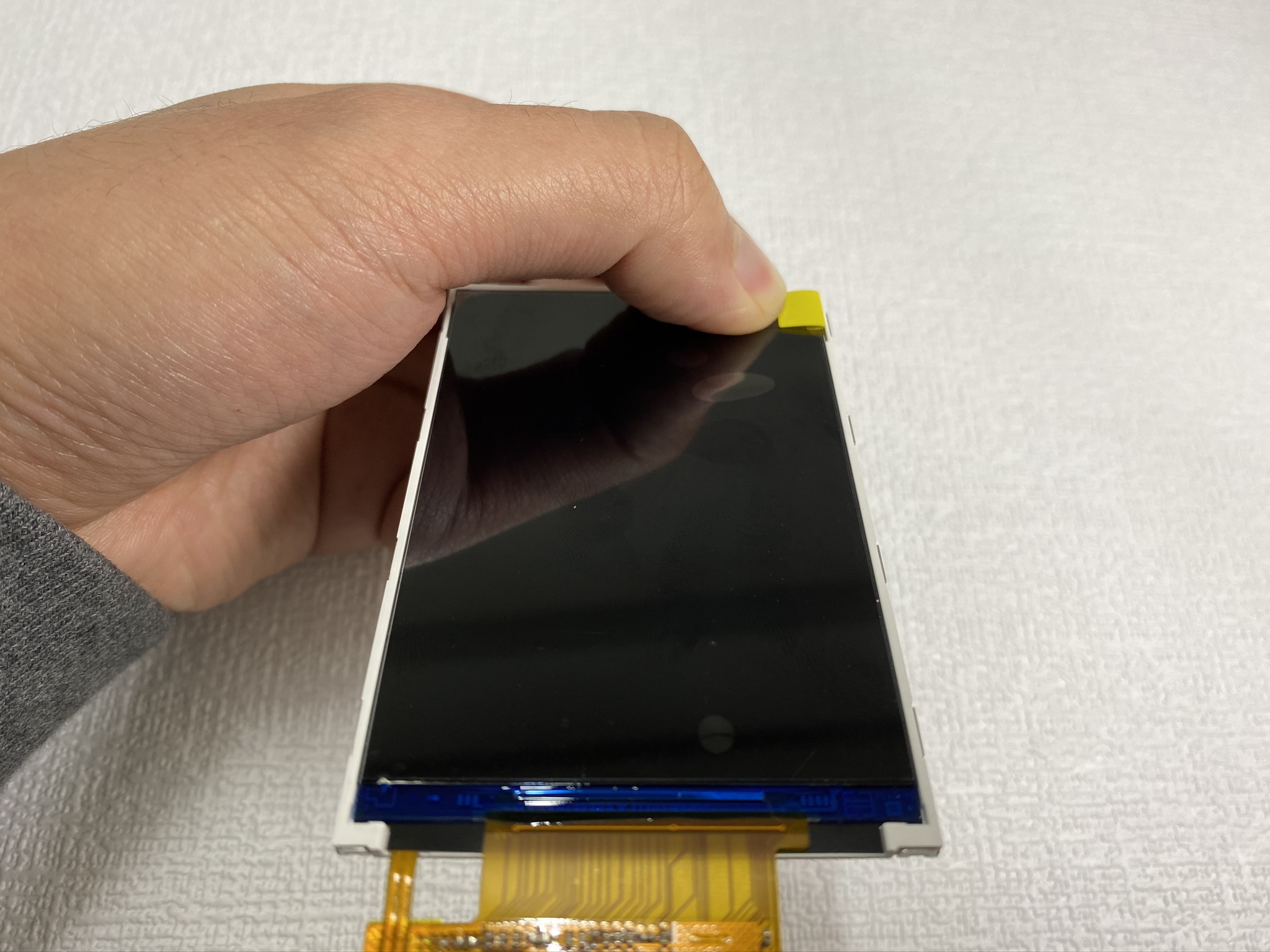
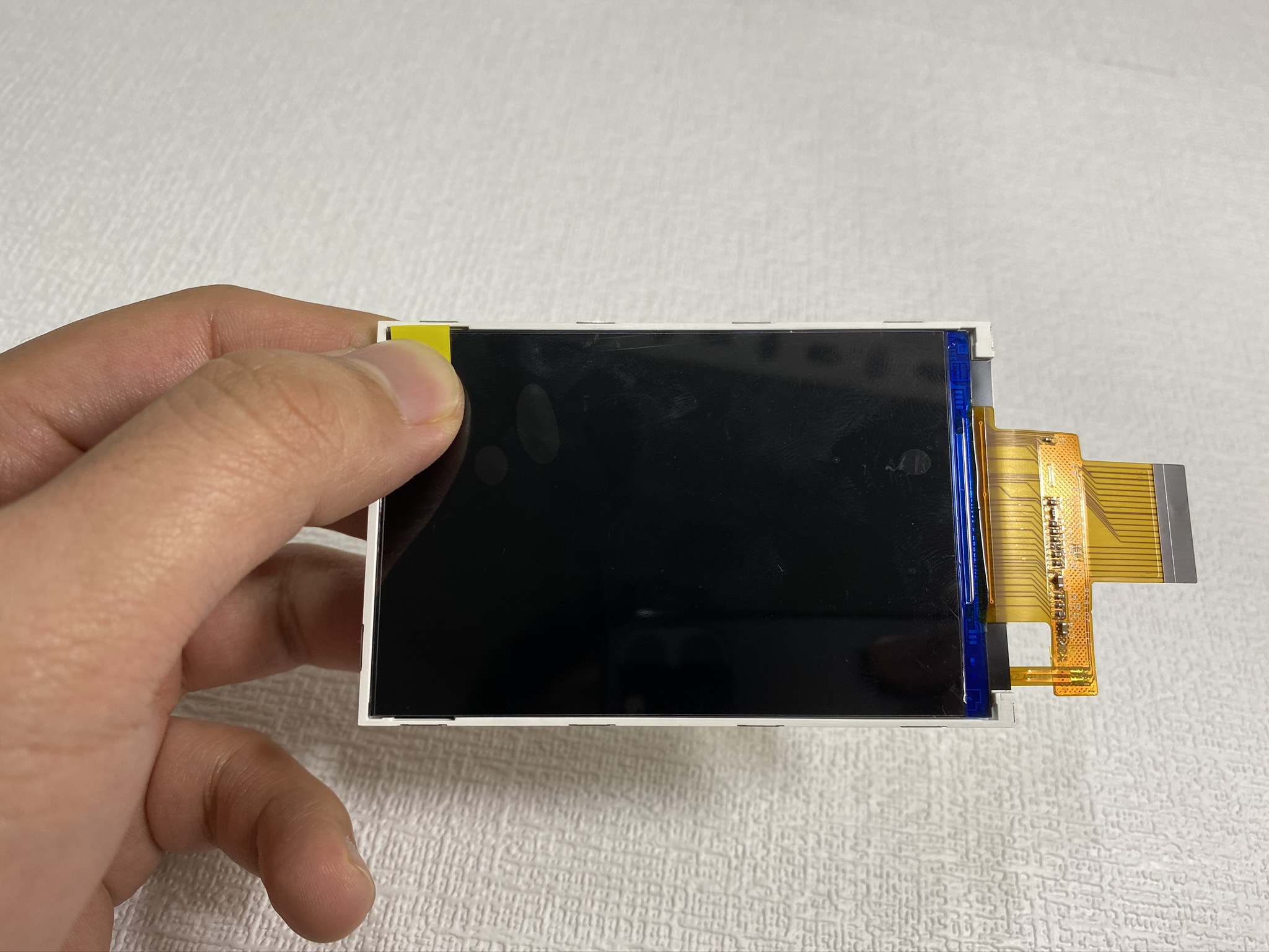
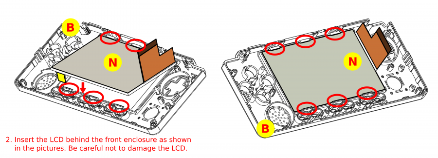
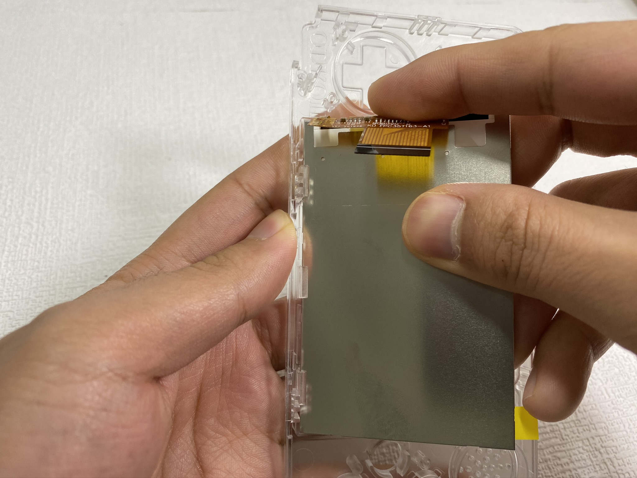
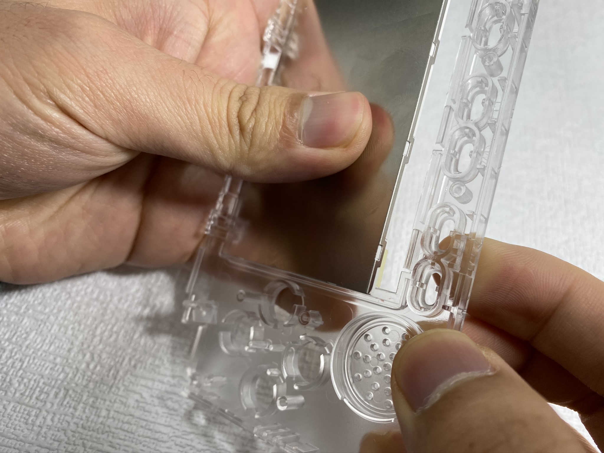
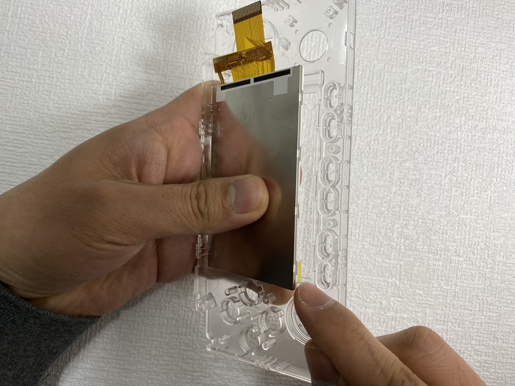
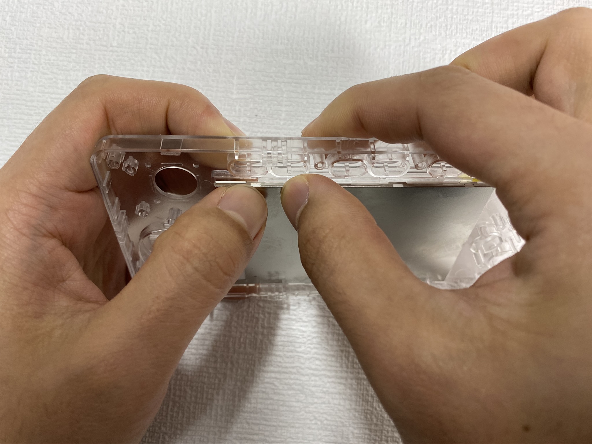
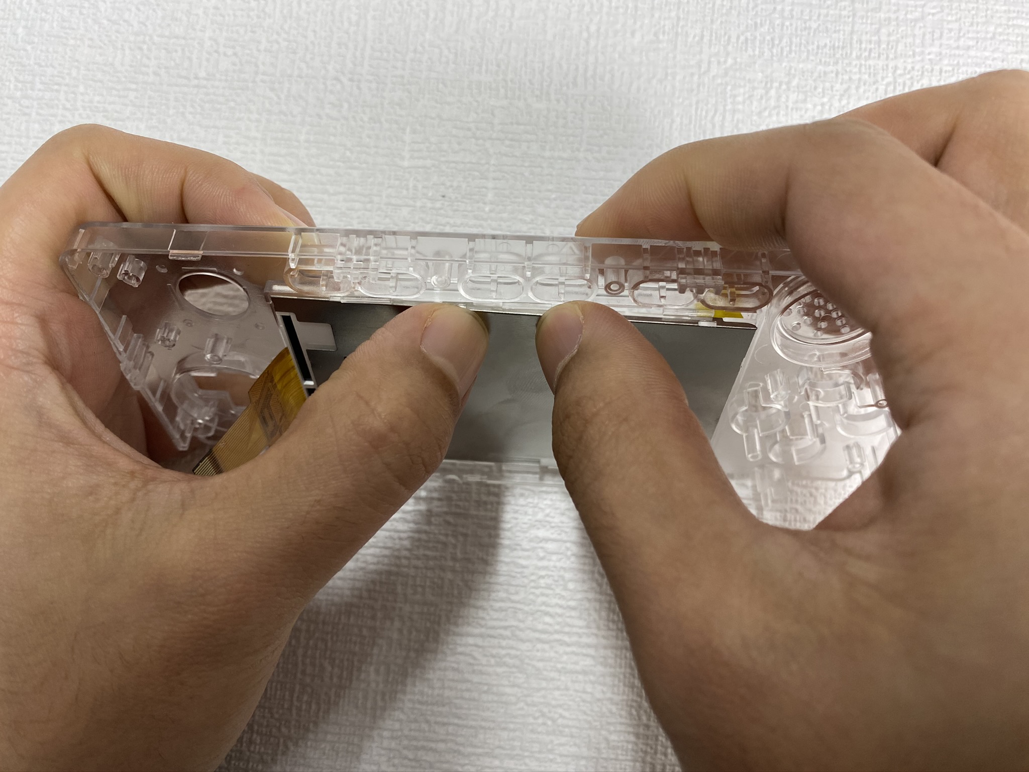
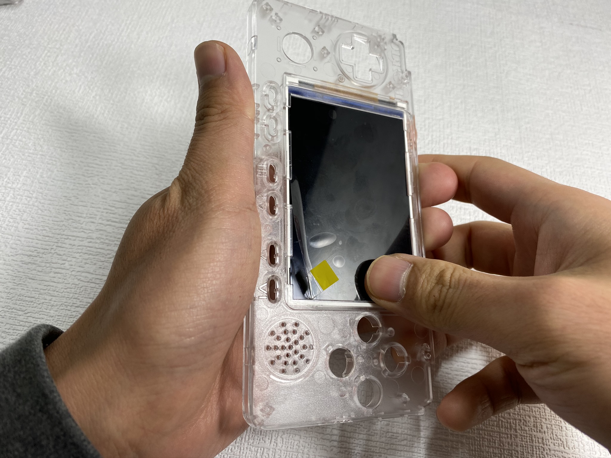

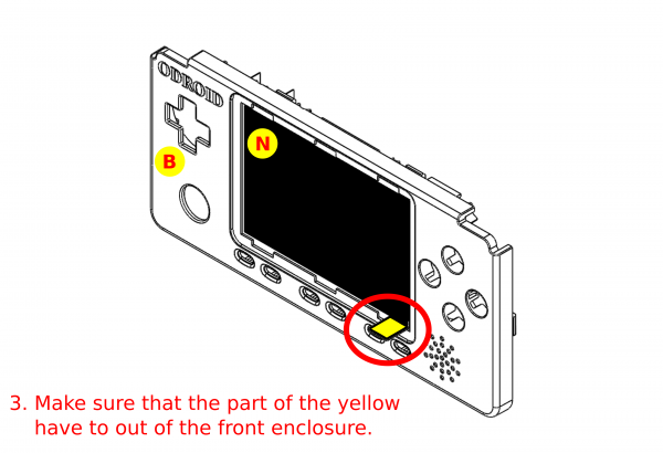
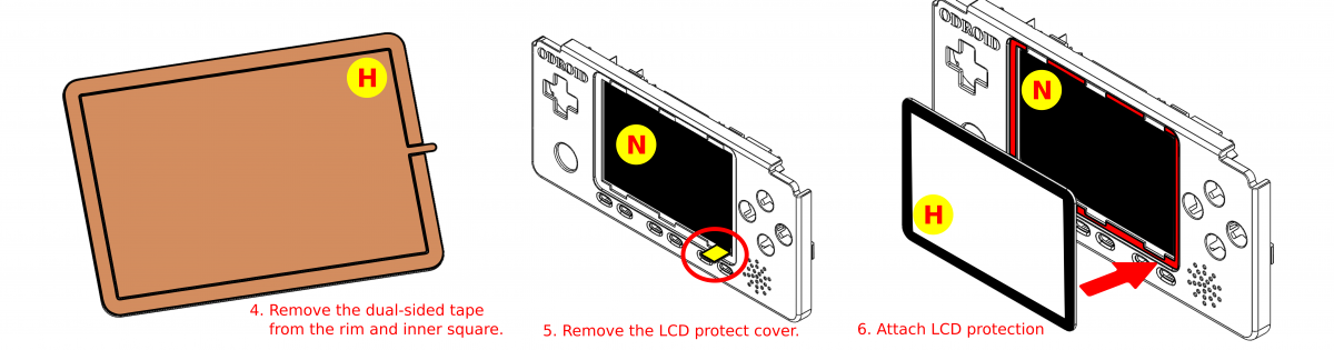
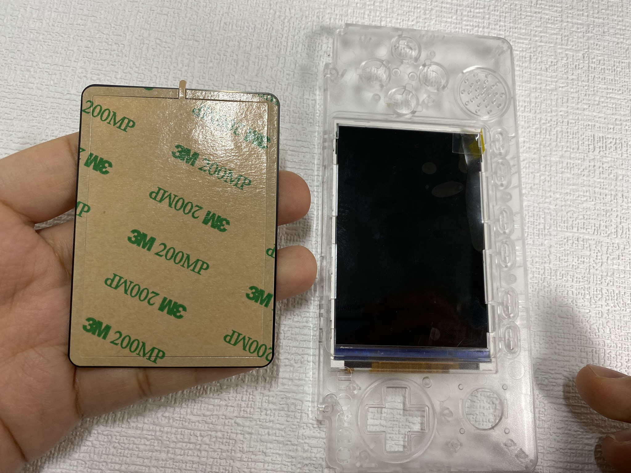

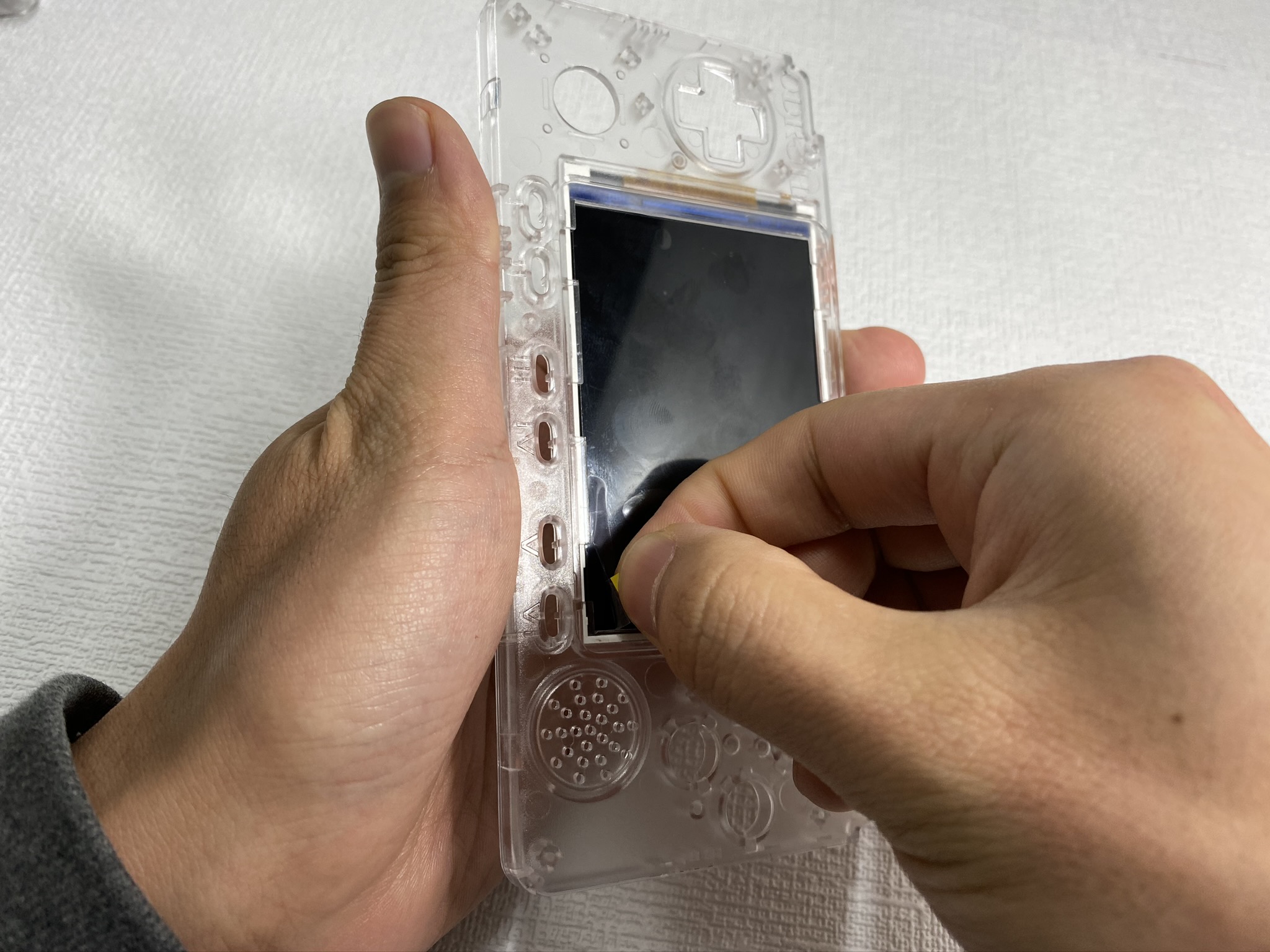
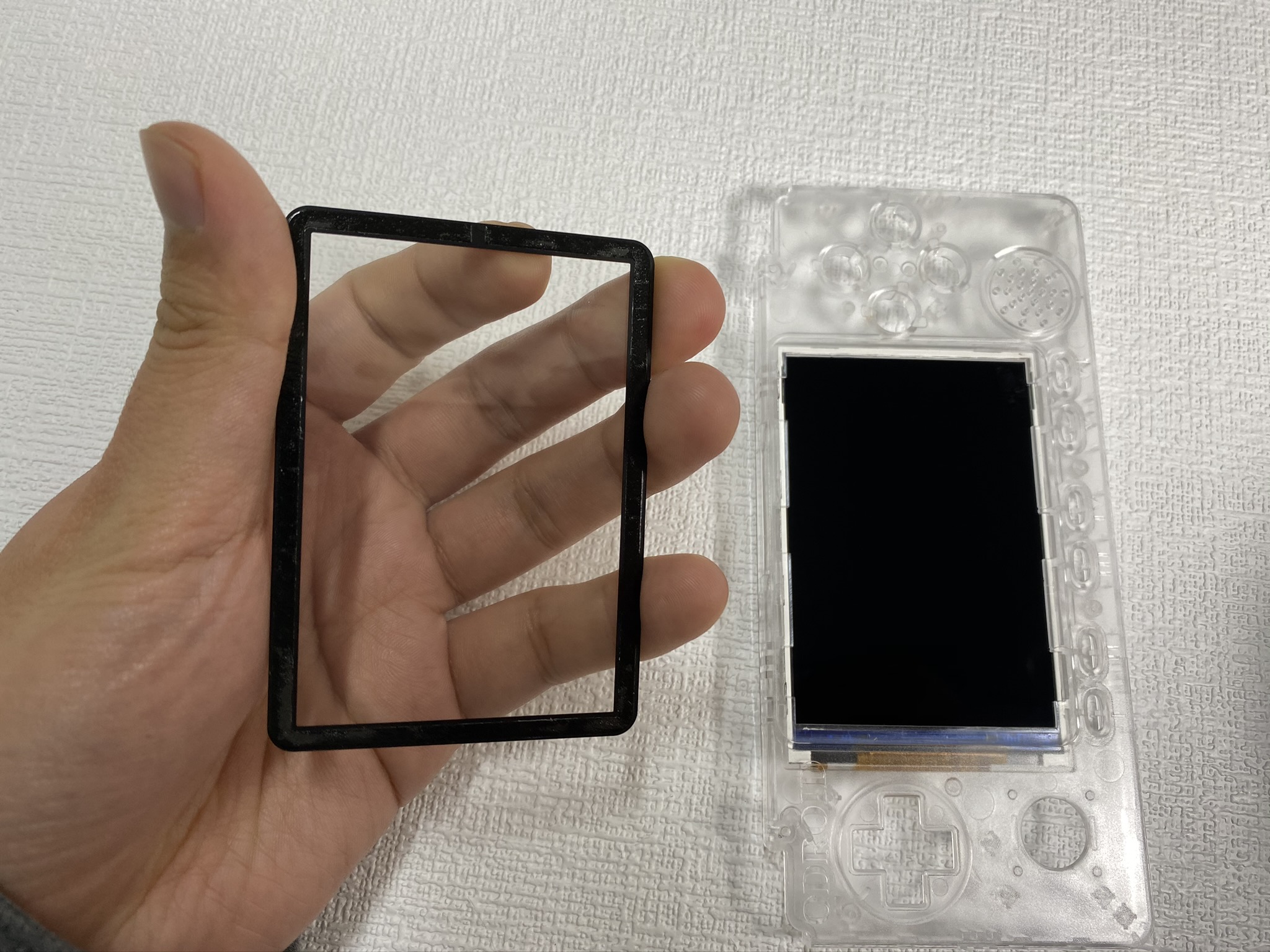
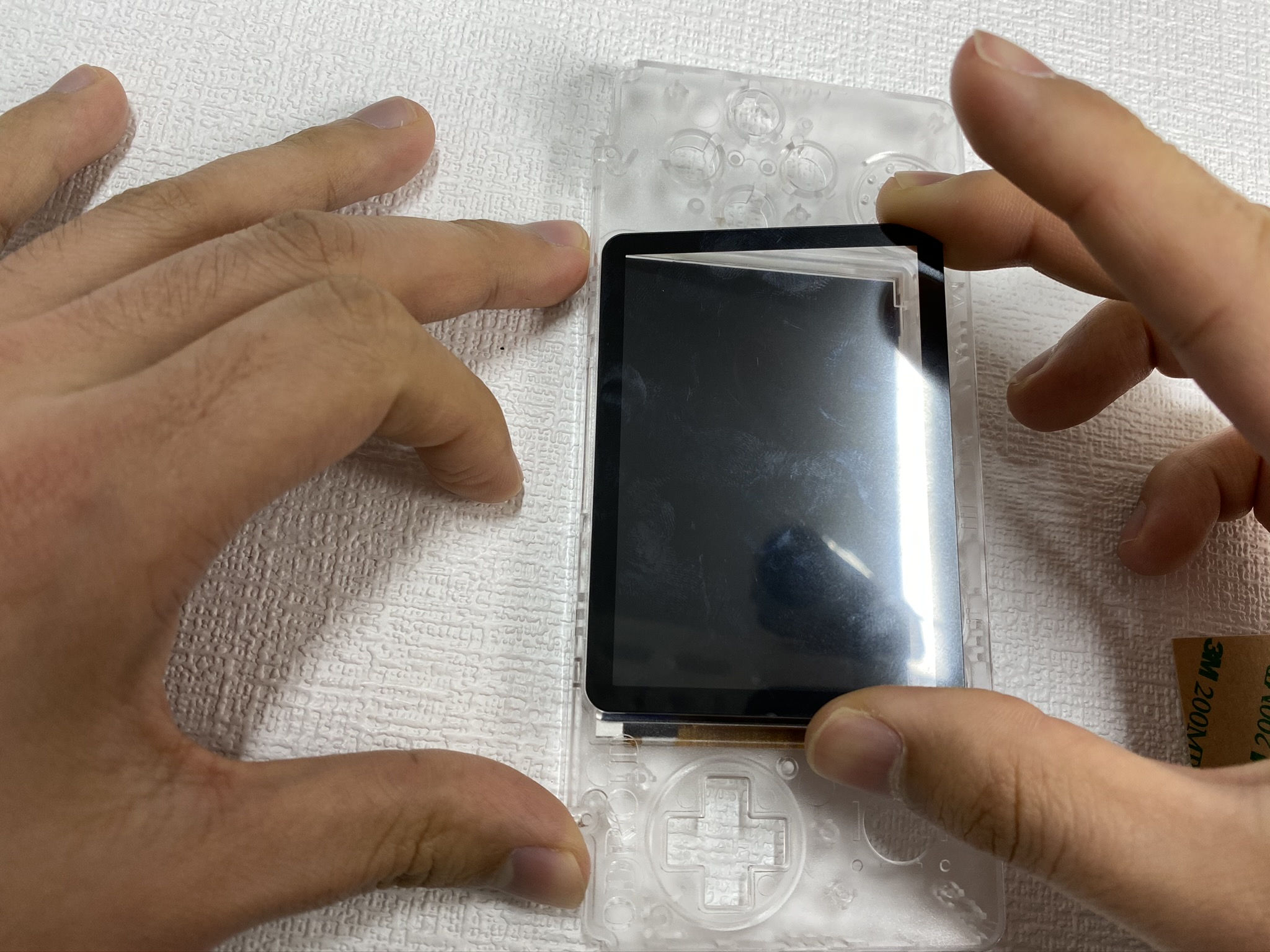
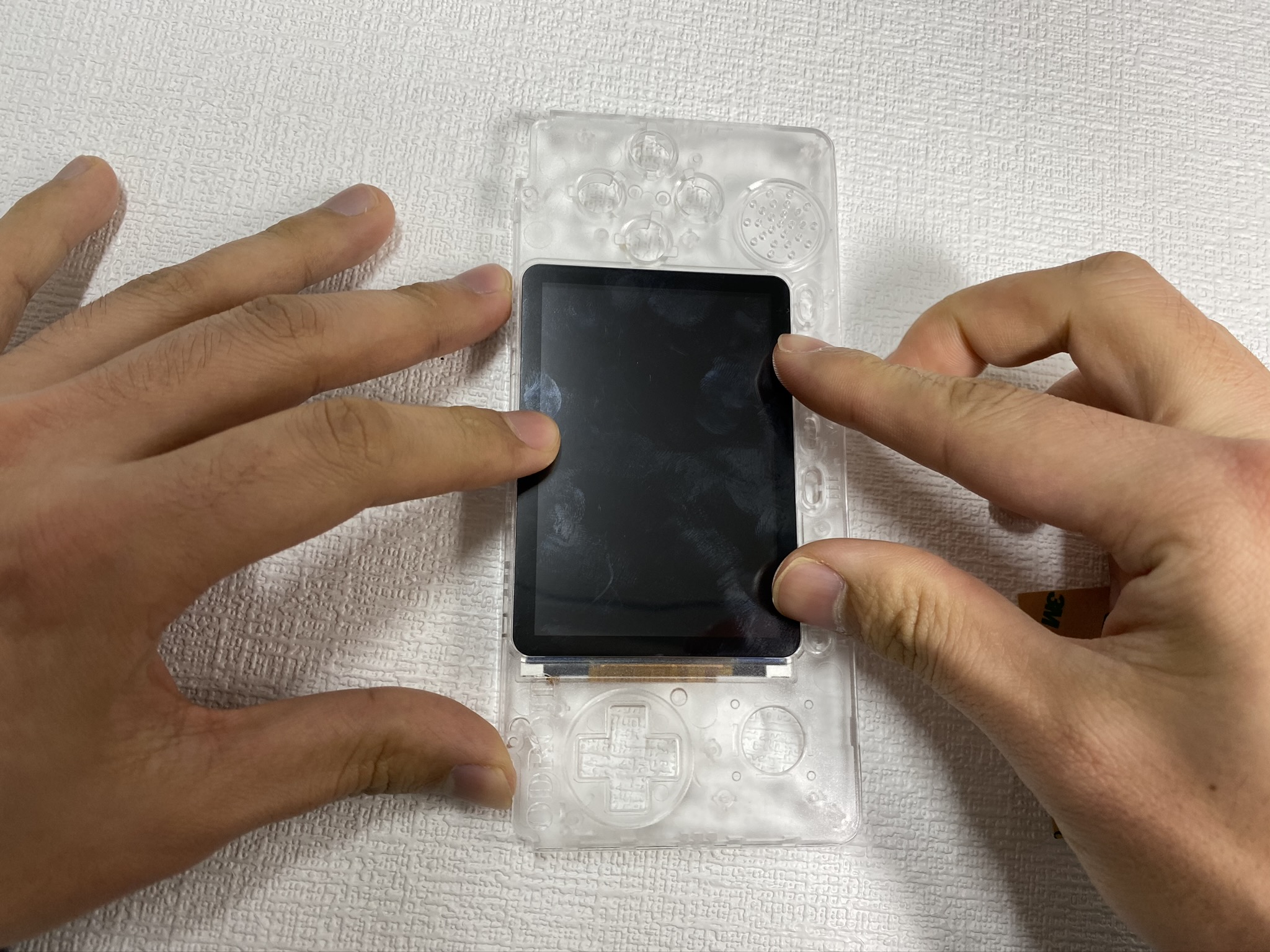
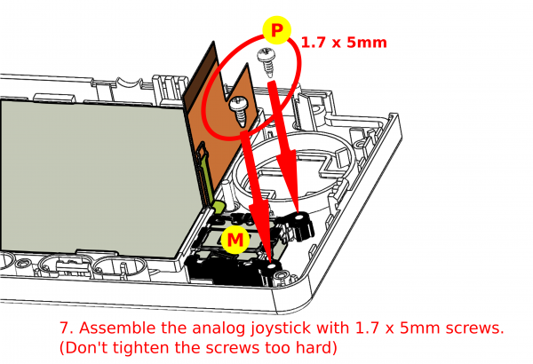
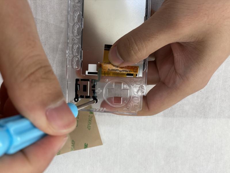
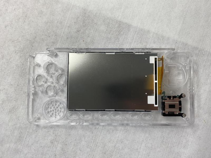
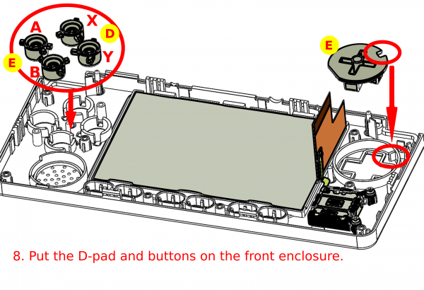 Figure 24 - Put the D-pad and buttons on the front enclosure
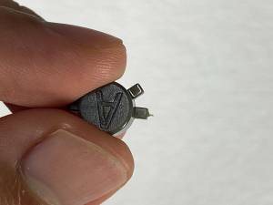
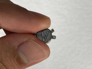
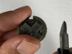 Figure 27 - Closeup of attaching the buttons
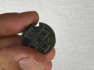
Be the first to comment