Una de las mejores características del ODROID-GO Advance es que puedes montarlo tú mismo, ya que viene en forma de kit. Esto significa que puedes aprender a encajan las piezas, hacerlo a modo de proyecto con tus hermanos, amigos o hijos, ¡y tener la satisfacción de jugar en un dispositivo verdaderamente único montado por ti mismo!
Para ensamblar el ODROID-GO Advance, desempaquete todas las piezas y comprueba que están todas las que aparecen en la Figura 1. Se cuidadoso al conectar los cables a la PCB y asegúrate de no apretar en exceso ninguno de los tornillos. Lee todas las instrucciones y mira el video antes de empezar.
Figure 1 - ODROID-GO Advance kit annotated parts diagram
(Figure 1 - ODROID-GO Advance kit annotated parts diagram)
A
USB Type-A Power Cable
J
D-PAD rubber
B
Front enclosure
K
A, B, X, Y button rubber
C
Back enclosure
L
battery sticker
D
Plastic L/R trigger, X, Y, power Buttons
M
Analog joystick
E
Plastic D-pad, A, B Buttons
N
320×480 TFT LCD
F
ODROID-GO-Advance board
O
0.5W speaker
G
3000mAh battery
P
1.7×5 screws 7pcs
H
LCD window
Q
1.7×8 screws 4pcs
I
I ~ VI button rubber
R
Screw driver
Instrucciones de Montaje
El video https://youtu.be/FsfpAkKGEXc muestra instrucciones detalladas sobre cómo usar el kit, te recomiendo que le eches un vistazo junto con las instrucciones que detallo a continuación con el fin de garantizar que todo sea montado correctamente.
Montaje LCD
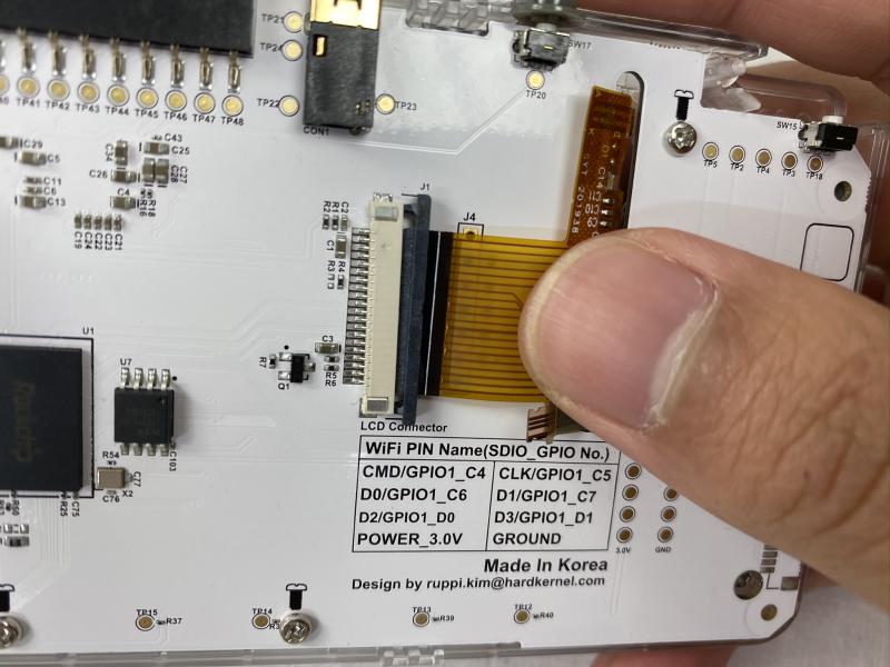
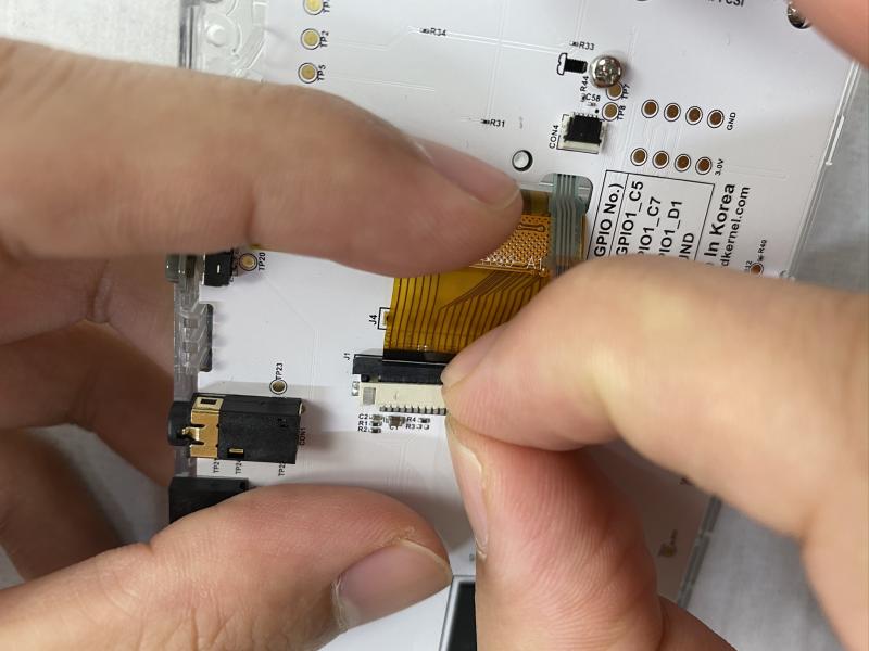
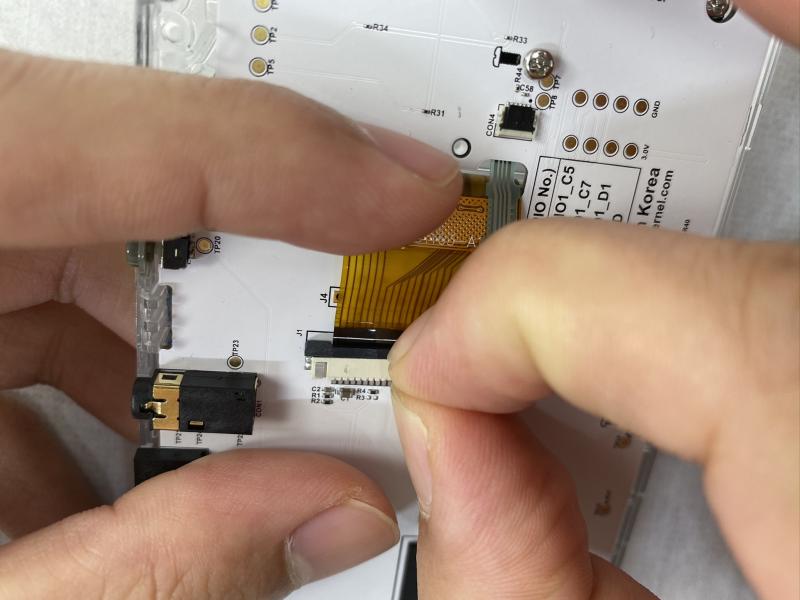
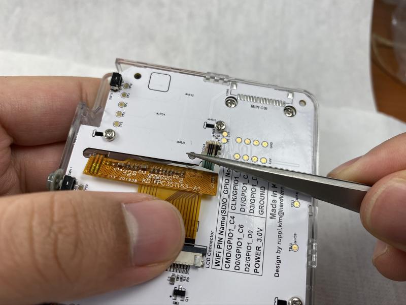
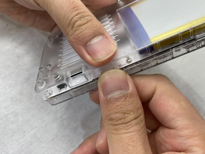
Figura 2: Pliega la pestaña amarilla tal y como se muestra
Figura 3- Primer plano de la inserción del panel LCD
Figura 4 - Primer plano de la pestaña amarilla
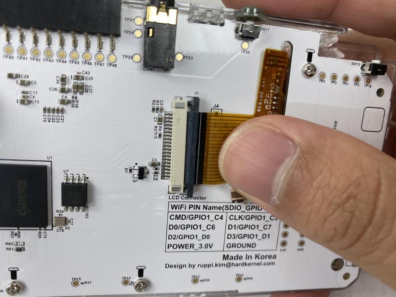
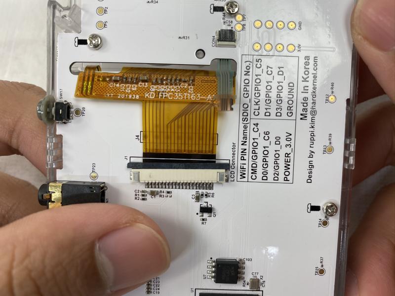
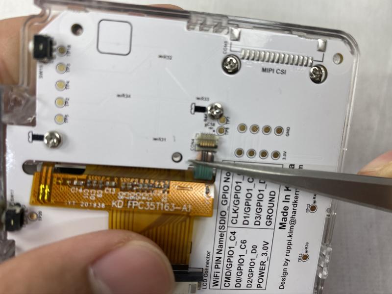
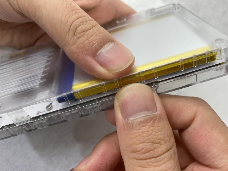
Figura 5- Inserta el panel LCD tal como se muestra
Figura 6- Primer plano del montaje del panel LCD
Figura 7 - Primer plano del montaje del panel LCD
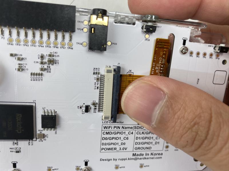
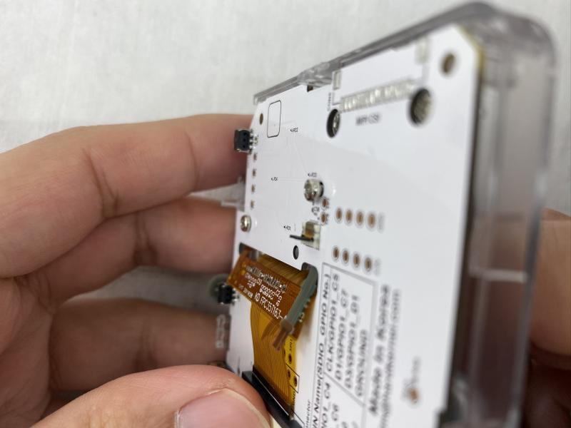
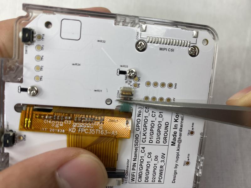
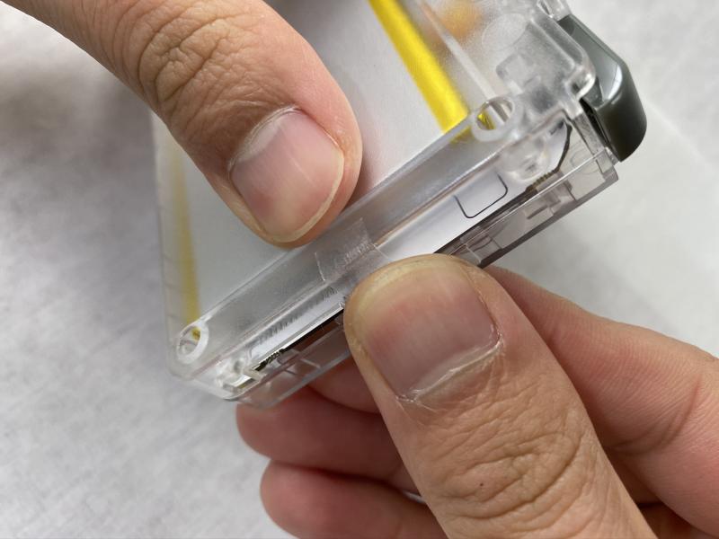
Figura 8 - Primer plano del montaje del panel LCD
Figura 9 - Primer plano del montaje del panel LCD
Figura 10 - Primer plano del montaje del panel LCD
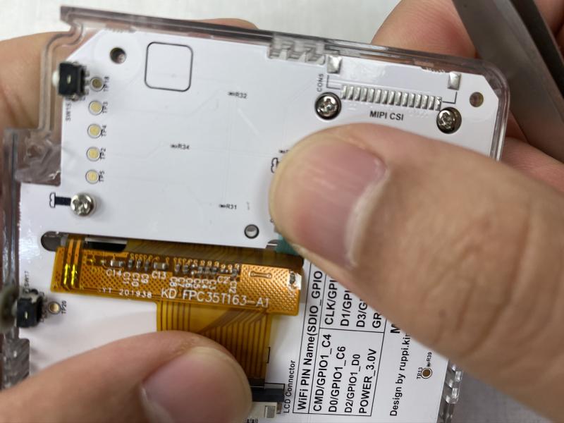
Figura 11 - Primer plano del montaje del panel LCD
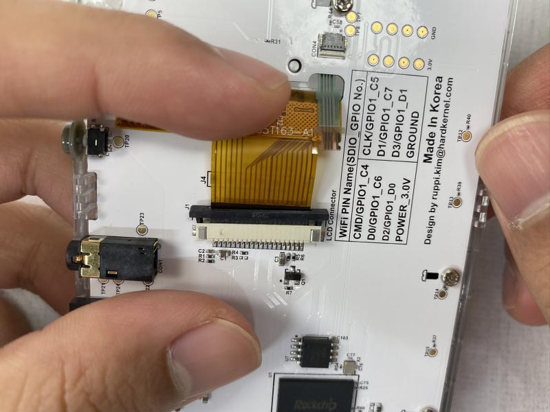
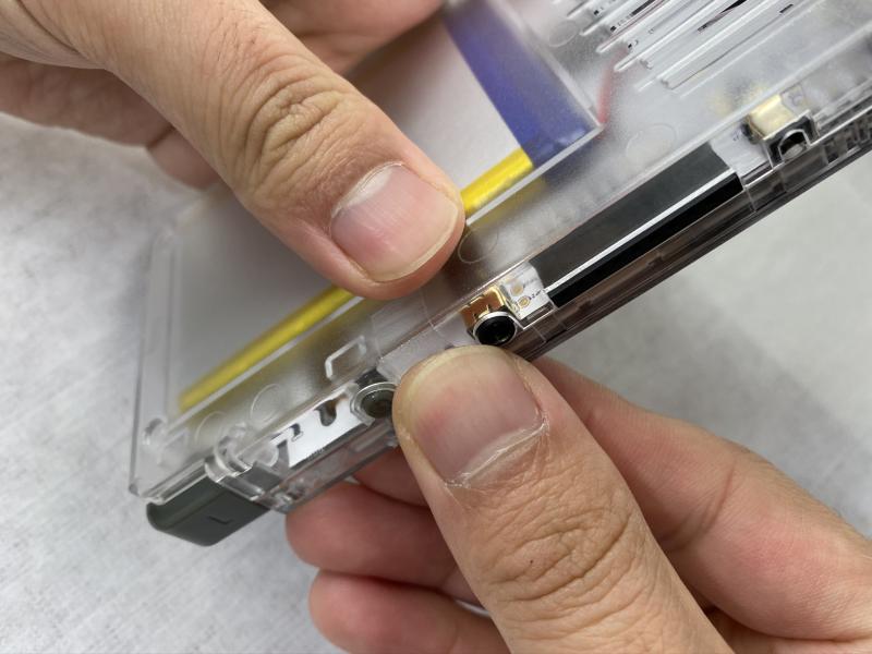
Insertar la pantalla LCD
Figura 12: Asegúrate de que la pestaña amarilla queda por delante
Figura 13 - Primer plano del montaje del panel LCD
Figura 14: Retira con cuidado la parte posterior de la cinta adhesiva de doble cara, extrae la cubierta protectora de la pantalla LCD tirando de la pestaña amarilla y coloca con cuidado el protector de la pantalla LCD con la cinta adhesiva de doble cara expuesta
Figura 15 - Primer plano retirando la cinta de doble cara
Figura 16 - Primer plano retirando la cinta de doble cara
Figura 17 - Primer plano retirando la cinta de doble cara
Figura 18 - Primer plano retirando la cinta de doble cara
Figura 19 - Primer plano retirando la cinta de doble cara
Figura 20 - Primer plano retirando la cinta de doble cara
Tienes más instrucciones de montaje del panel LCD en el video https://youtu.be/ShFrKvPcjsE.
Montaje del joystick analógico
Figura 21: ensambla el joystick analógico con tornillos de 1.7 x 5 mm, asegurándote de no apretar demasiado los tornillos
Figura 22 - Primer plano del montaje del joystick analógico
Figura 23 - Primer plano del montaje del joystick analógico
Montaje de los botones
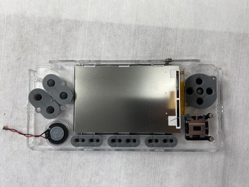
Figura 24: Coloque el D-pad y los botones en la carcasa frontal
Figura 25 - Primer plano de montaje de los botones
Figura 26 - Primer plano de montaje de los botones
Figura 27 - Primer plano de montaje de los botones
Figura 28 - Primer plano de montaje de los botones
Figura 29 - Primer plano de montaje de los botones
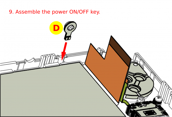
Figura 30: Montaje del botón de encendido
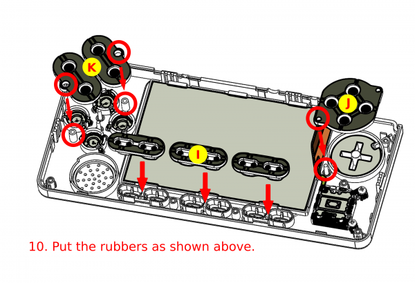
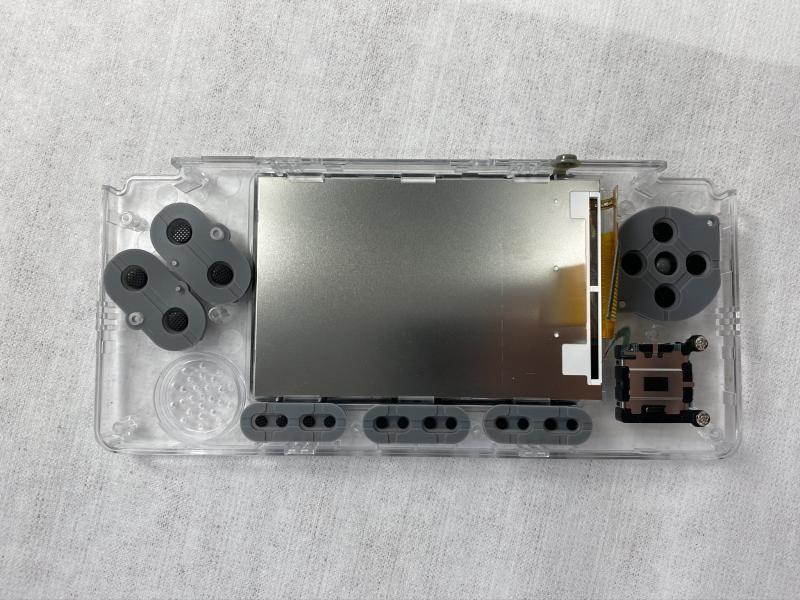
Figura 31: Inserta los botones de goma en la carcasa
Figura 32 - Primer plano del montaje de los botones de goma
Montaje de altavoces
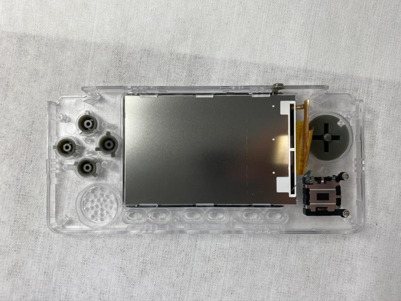
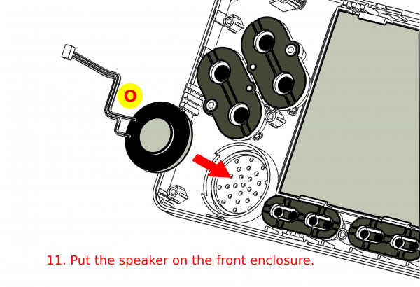
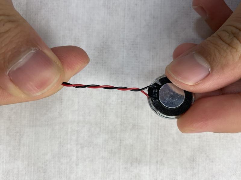
Figura 33: inserta el altavoz en la carcasa frontal
Figura 34 - Primer plano del montaje del altavoz
Figura 35 - Primer plano del montaje del altavoz
Montaje de la placa PCB
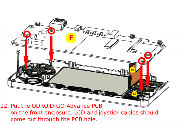
Figura 36: Coloca el PCB ODROID-GO Advance en la carcasa frontal
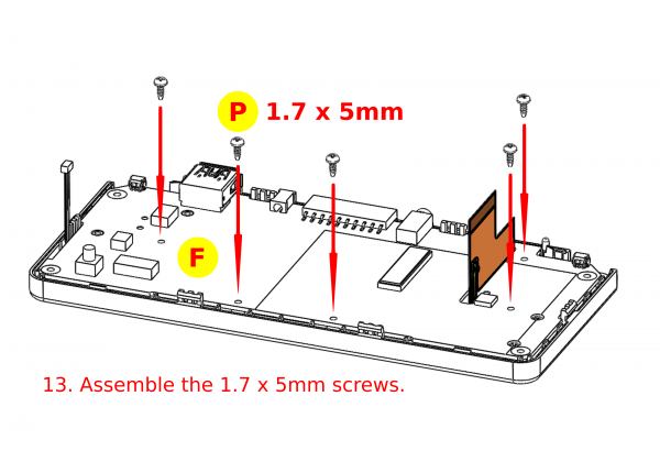
Figura 37: Inserte los tornillos de 1.7 x 5 mm
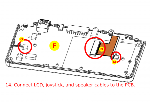
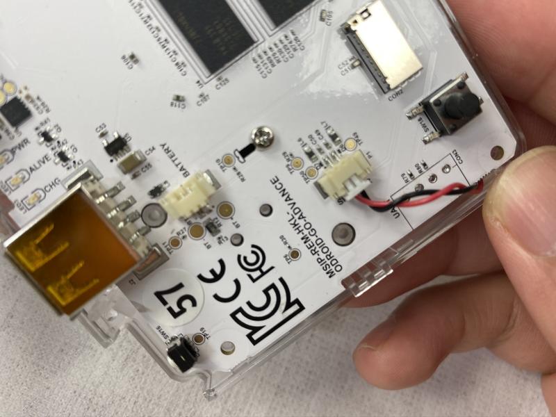
Figura 38: Conecta los cables de LCD, joystick y altavoz a la PCB
Nota: Nunca levante el conector del joystick más de 90 grados o se romperá.
Figura 39 - Primer plano del montaje de las conexiones de PCB
Figura 40 - Primer plano del montaje de las conexiones de PCB
Figura 41 - Primer plano del montaje de las conexiones de PCB
Figura 42 - Primer plano del montaje de las conexiones de PCB
Figura 43 - Primer plano del montaje de las conexiones de PCB
Figura 44 - Primer plano del montaje de las conexiones de PCB
Figura 45 - Primer plano del montaje de las conexiones de PCB
Figura 46 - Primer plano del montaje de las conexiones de PCB
Figura 47 - Primer plano del montaje de las conexiones de PCB
Figura 48 - Primer plano del montaje de las conexiones de PCB
Figura 49 - Primer plano del montaje de las conexiones de PCB
Figura 50 - Primer plano del montaje de las conexiones de PCB
Figura 51 Primer plano del montaje de las conexiones de PCB
Montaje de la batería
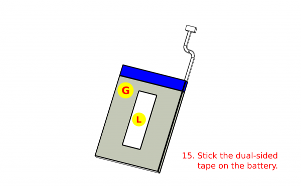
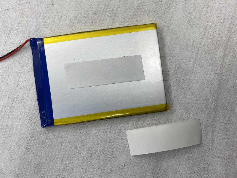
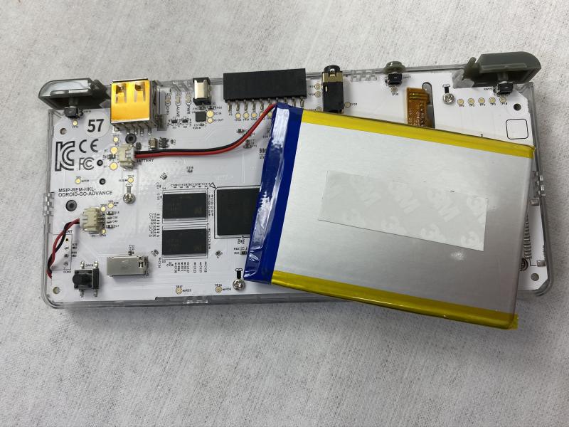
Figura 52: Pega la cinta de doble cara en la batería
Figura 53 - Cierre de la cinta de la batería
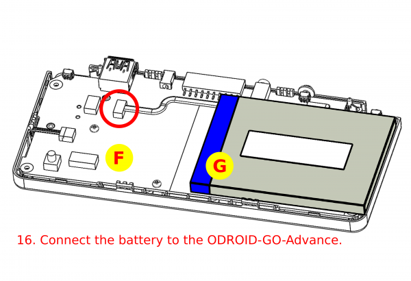
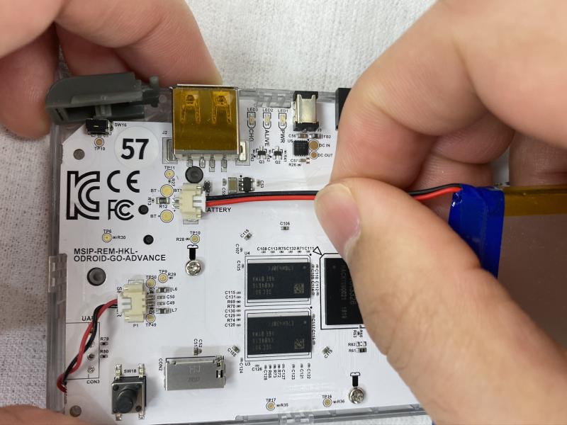
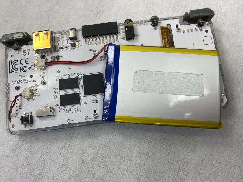
Figura 54 - Conecte la batería al ODROID-GO Advance.
Figura 55 - Conecta la batería al ODROID-GO Advance
Montaje de botones de gatillo
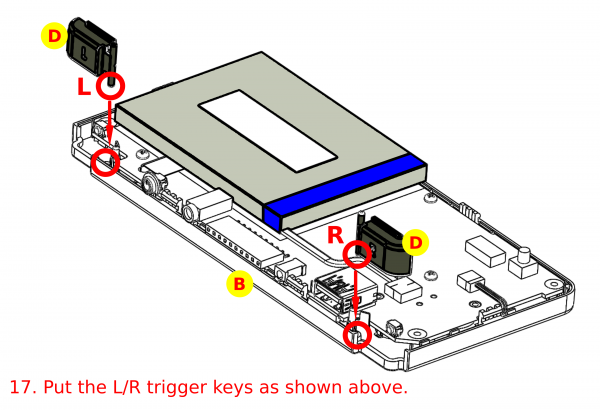
Figura 56: Inserta las teclas del botón de gatillo en las ranuras, asegurándote de alinearlas en los extremos izquierdo y derecho como se indica
Figura 57 - Cierre de las teclas del botón disparador
Montaje de la carcasa posterior
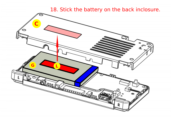
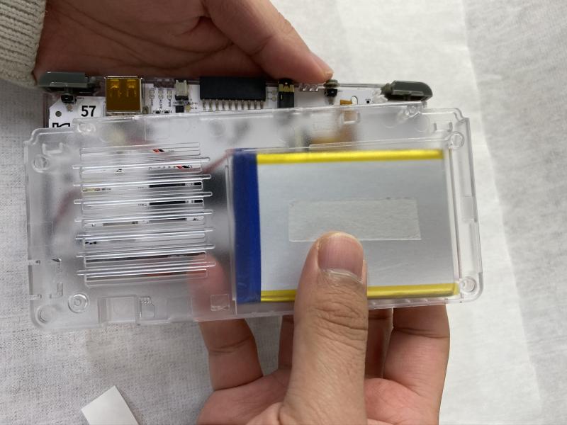
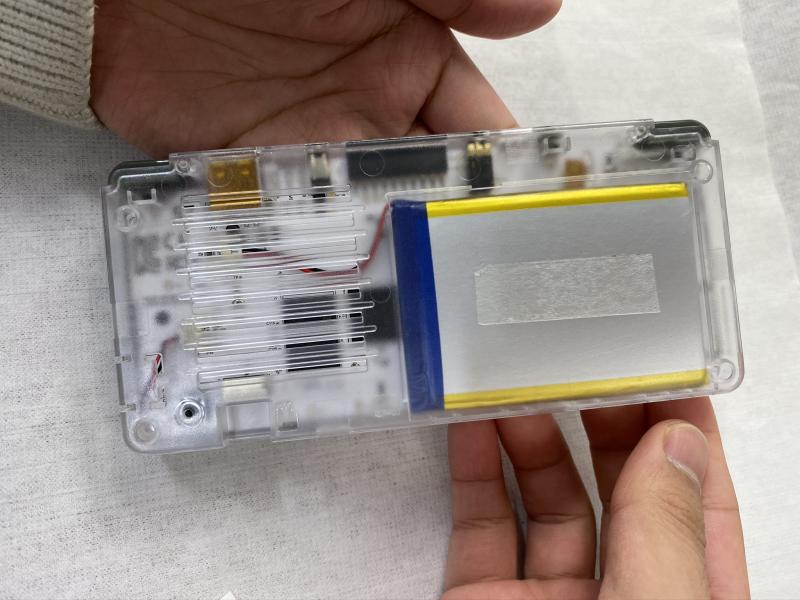
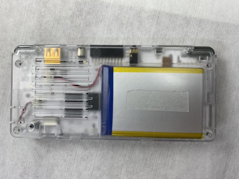
Figura 58: Pega la batería en la carcasa posterior
Figura 59 - Primer plano del accesorio de la batería
Figura 60 - Primer plano del accesorio de la batería
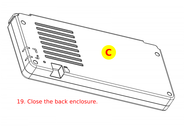
Figura 61 – Cierra la carcasa posterior
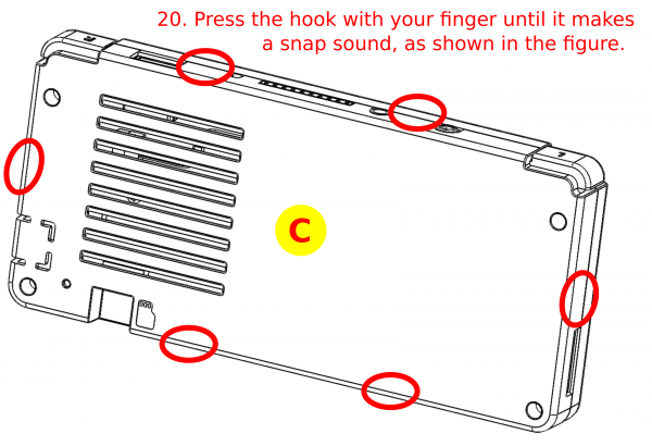
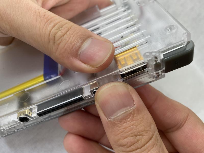
Figura 62: Presiona el gancho con el dedo hasta que emita un chasquido
Figura 63 - Primer plano de la fijación de la carcasa
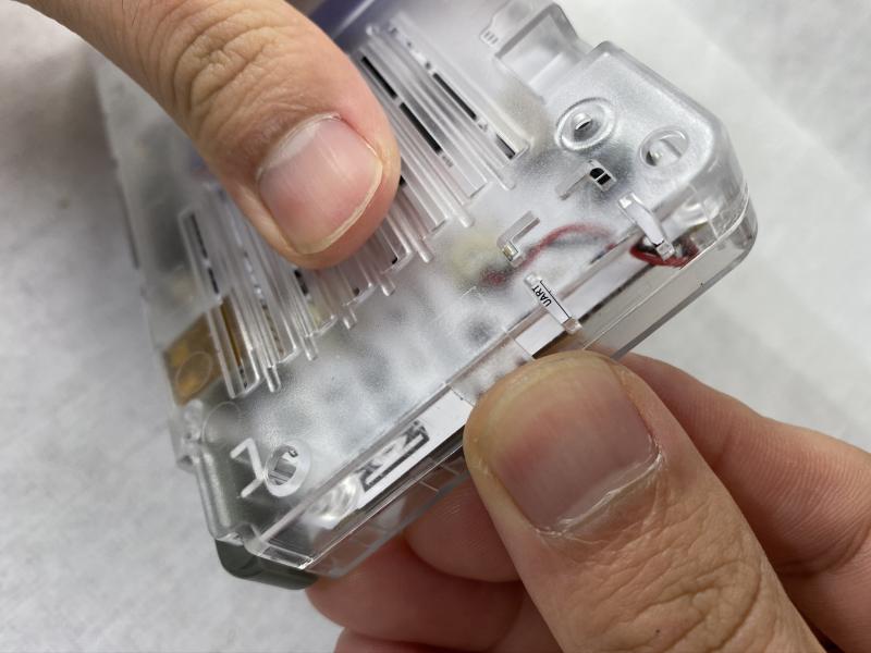
Figura 64: primer plano del anclaje de la carcasa
Figura 65 - primer plano del anclaje de la carcasa
Figura 66 - primer plano del anclaje de la carcasa
Figura 67 - primer plano del anclaje de la carcasa
Figura 68 - primer plano del anclaje de la carcasa
Figura 69 - primer plano del anclaje de la carcasa
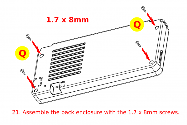
Figura 70: Monta la carcasa posterior con los tornillos de 1.7 x 8 mm, teniendo cuidado de no apretarlos demasiado
Figura 71 - ODROID-GO Advance completamente ensamblado


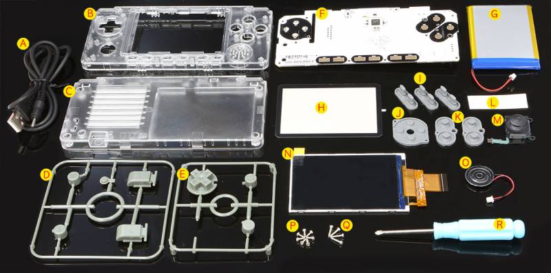
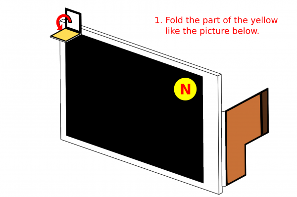 Figura 2: Pliega la pestaña amarilla tal y como se muestra
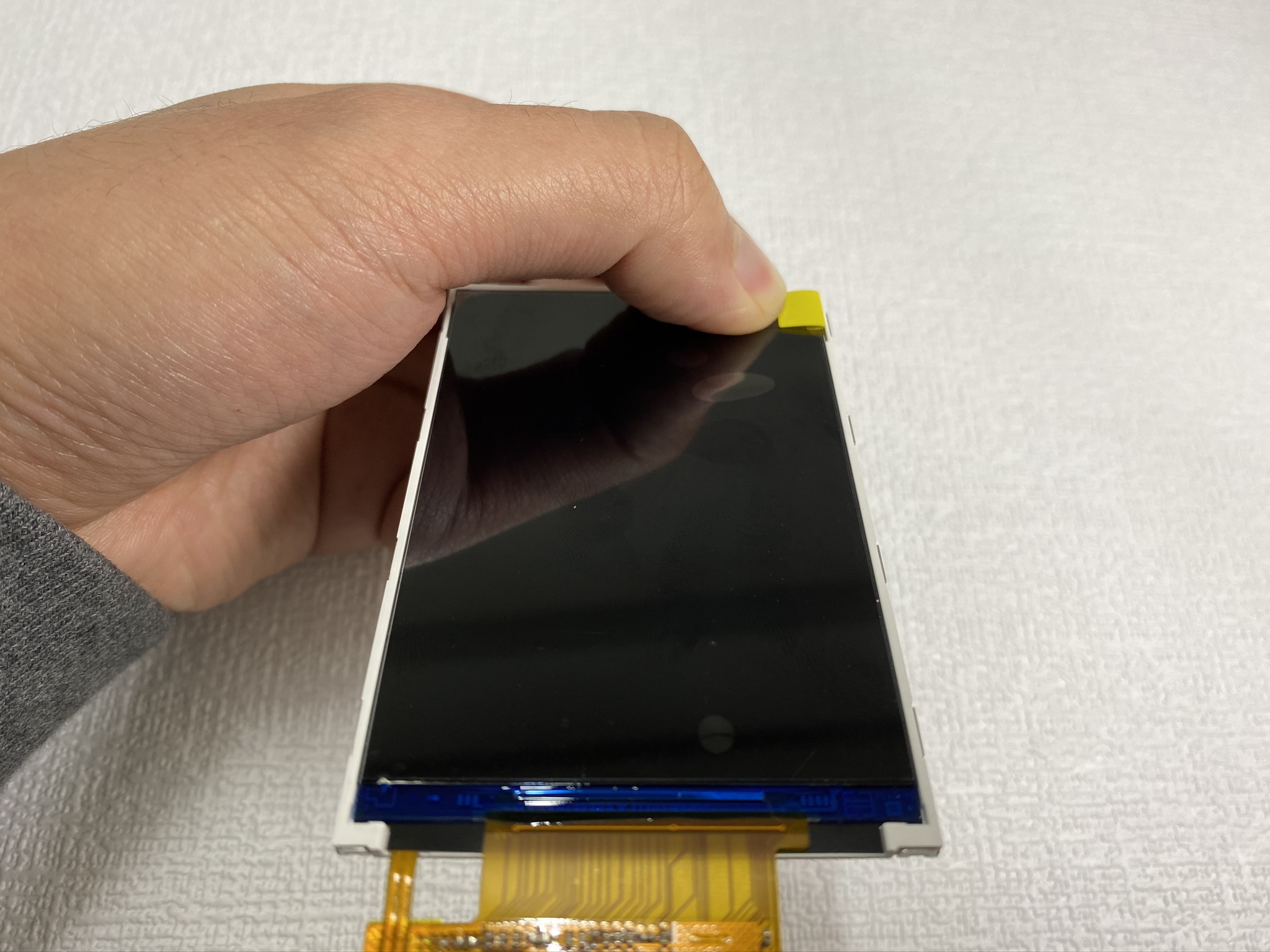
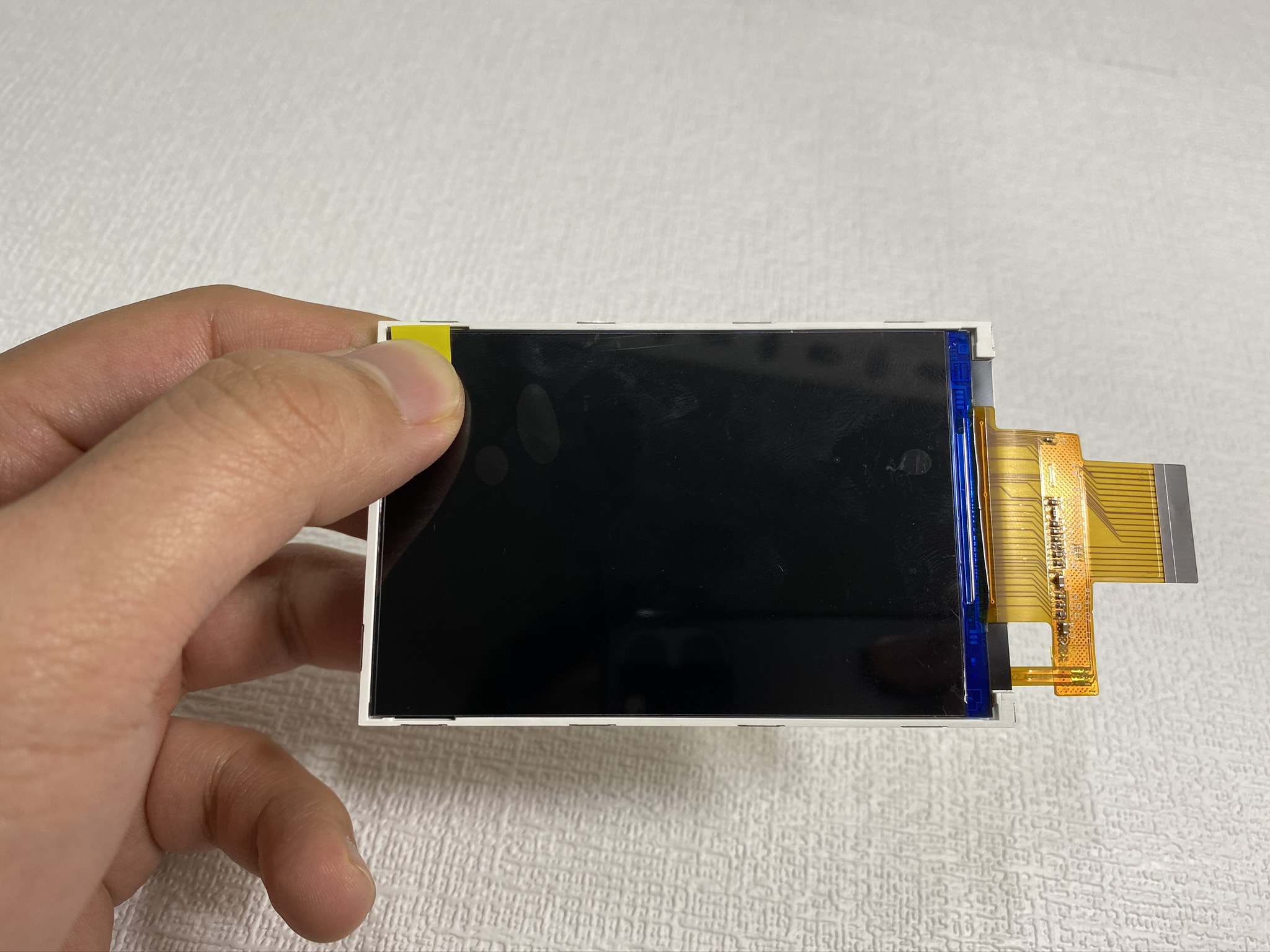
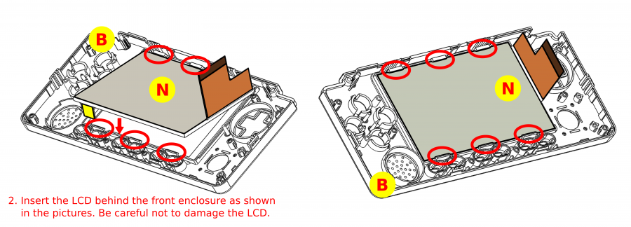
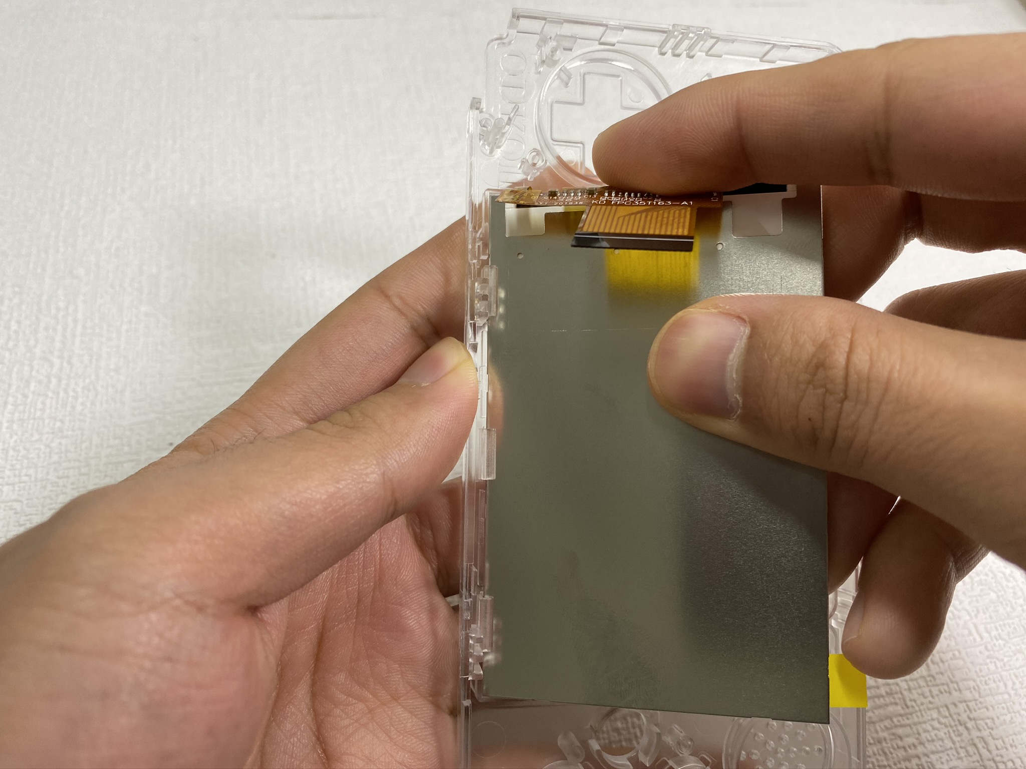
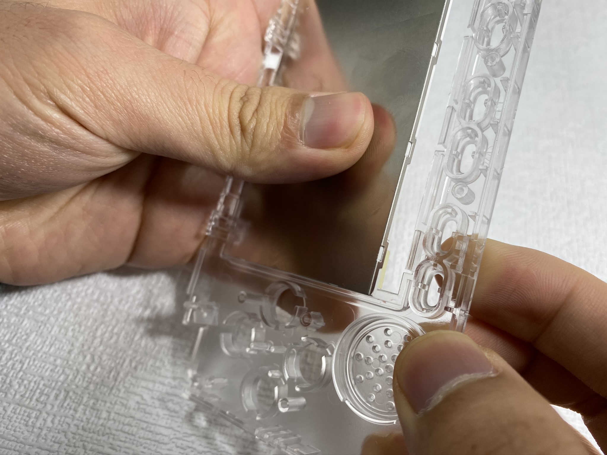
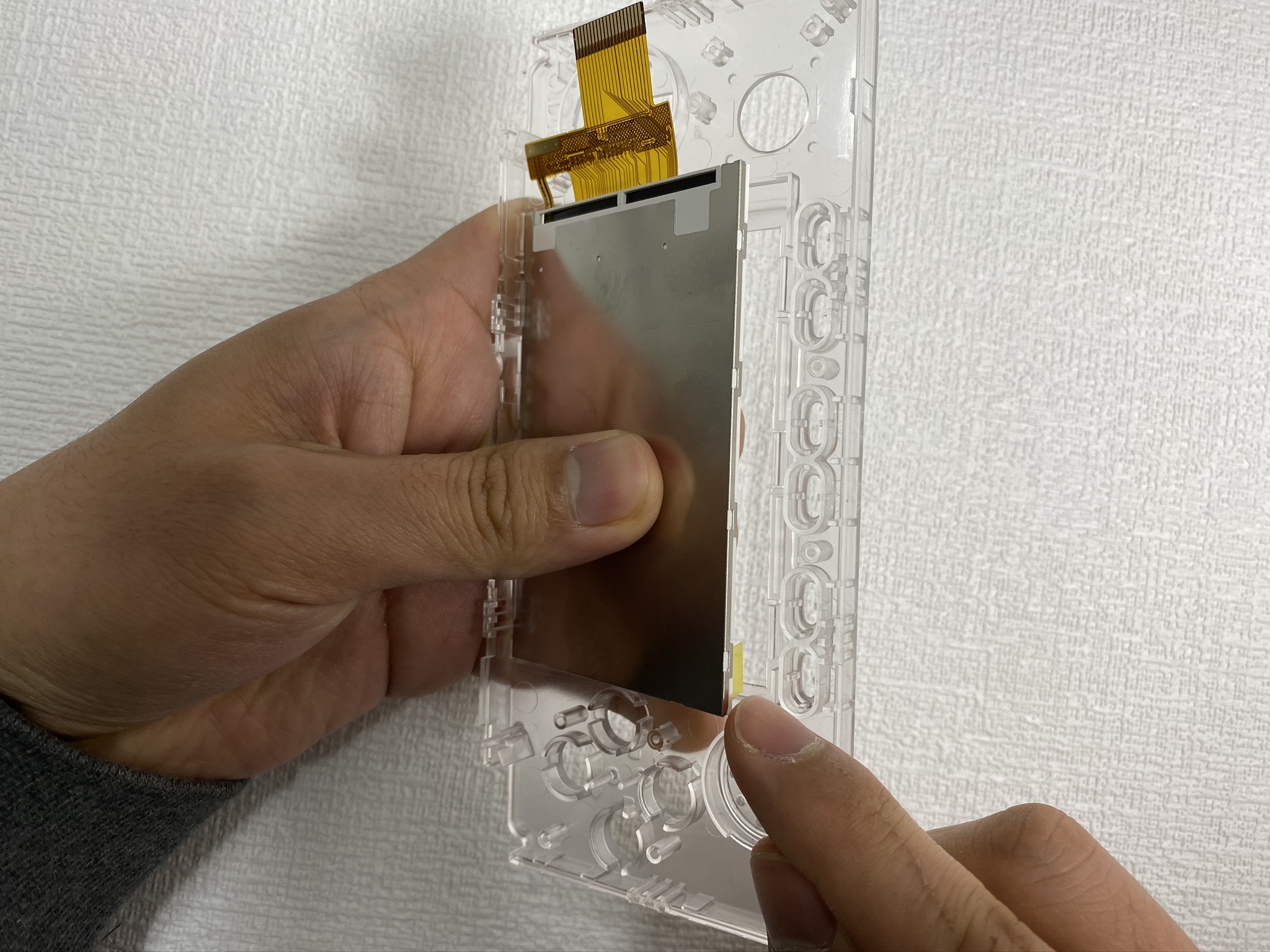
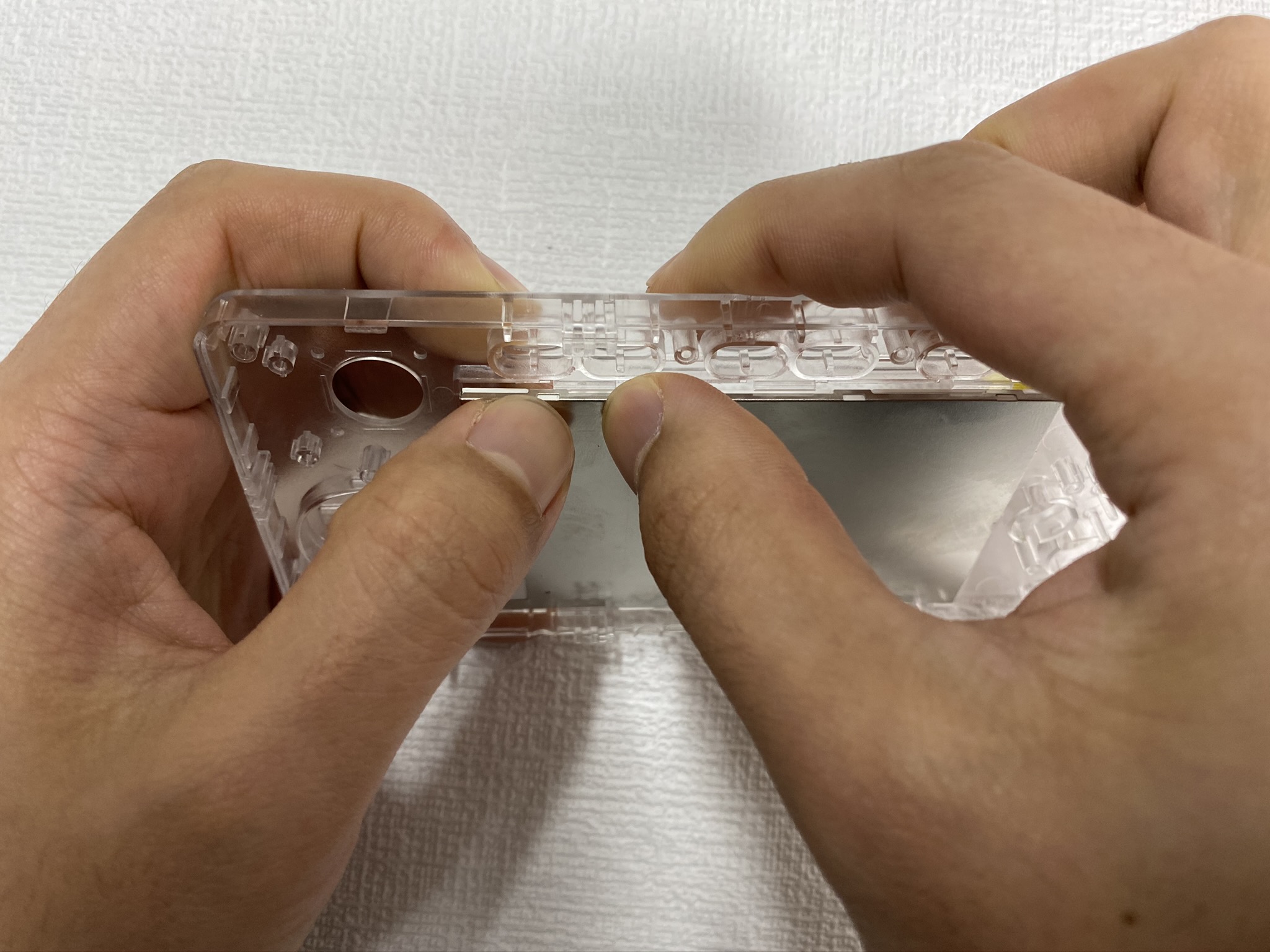
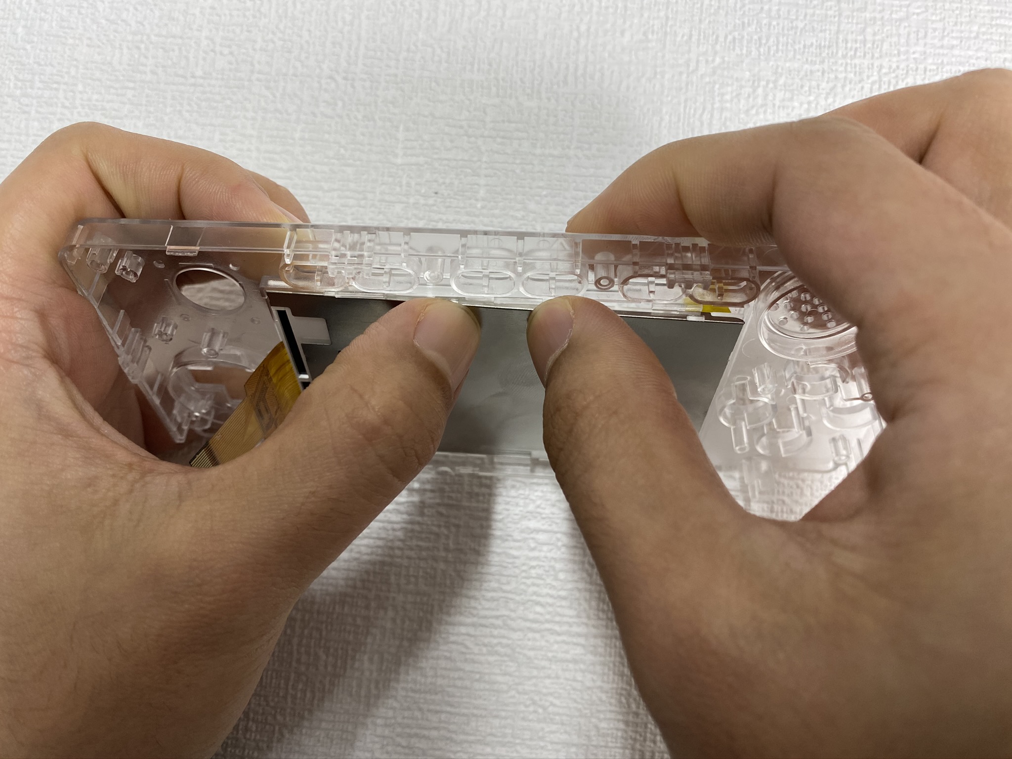
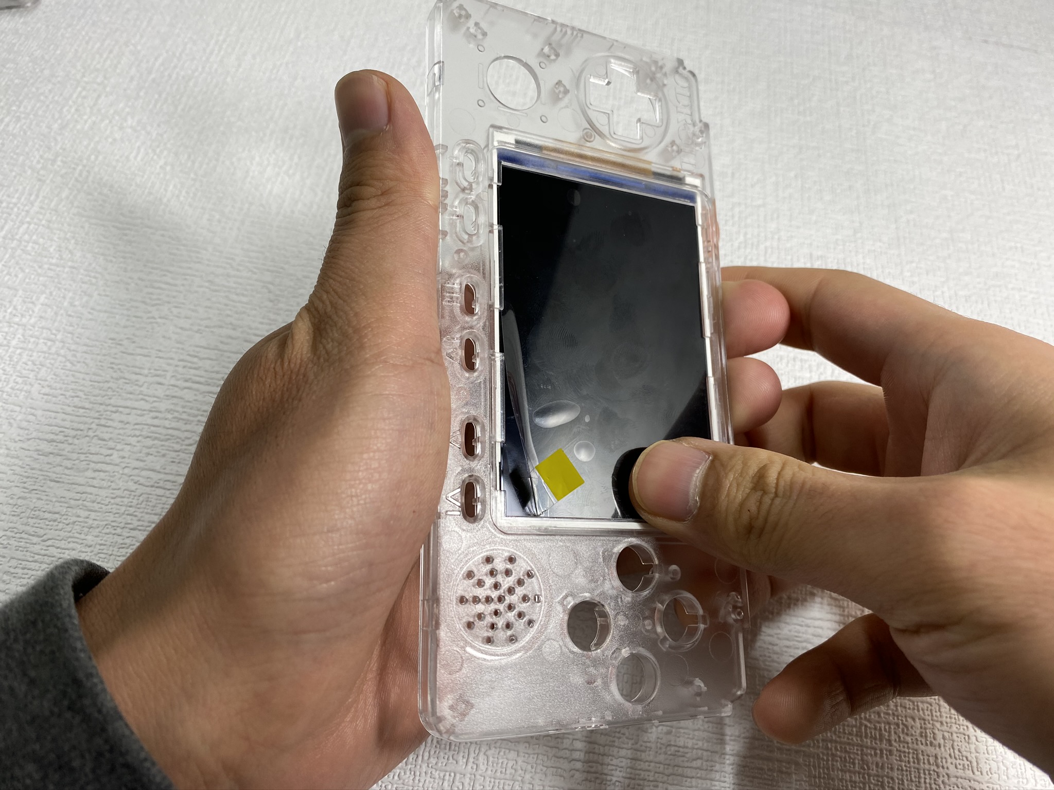

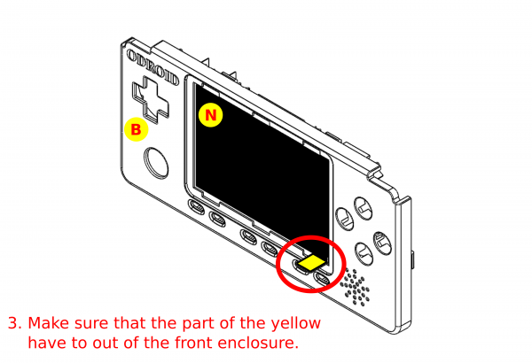
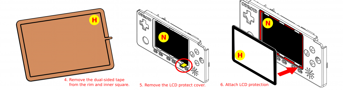
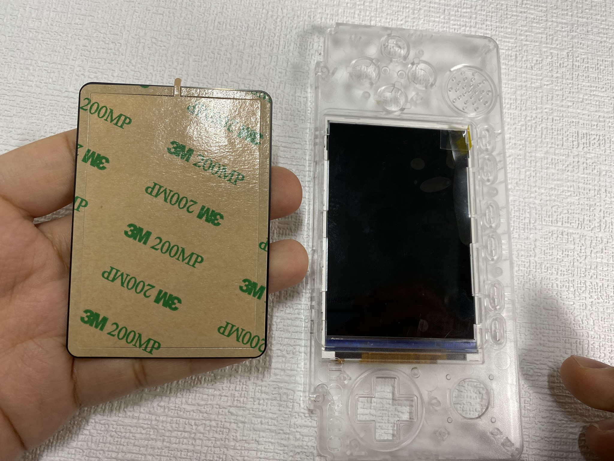

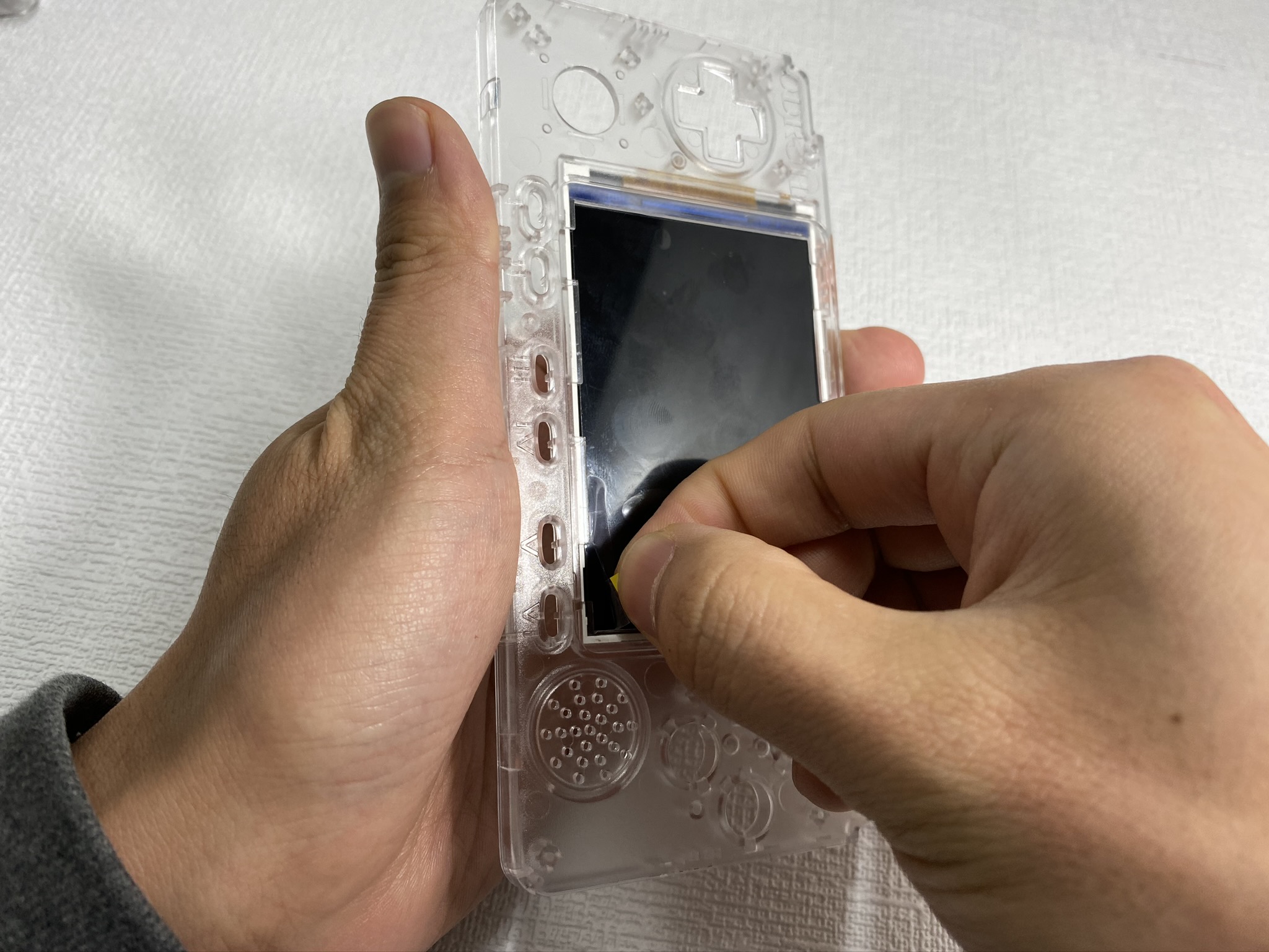
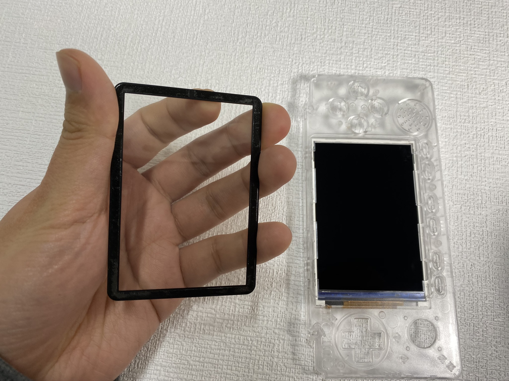
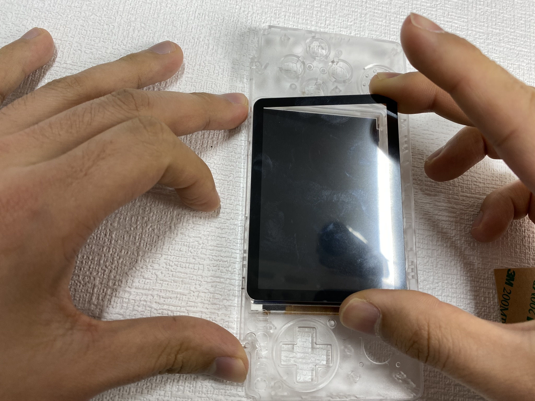
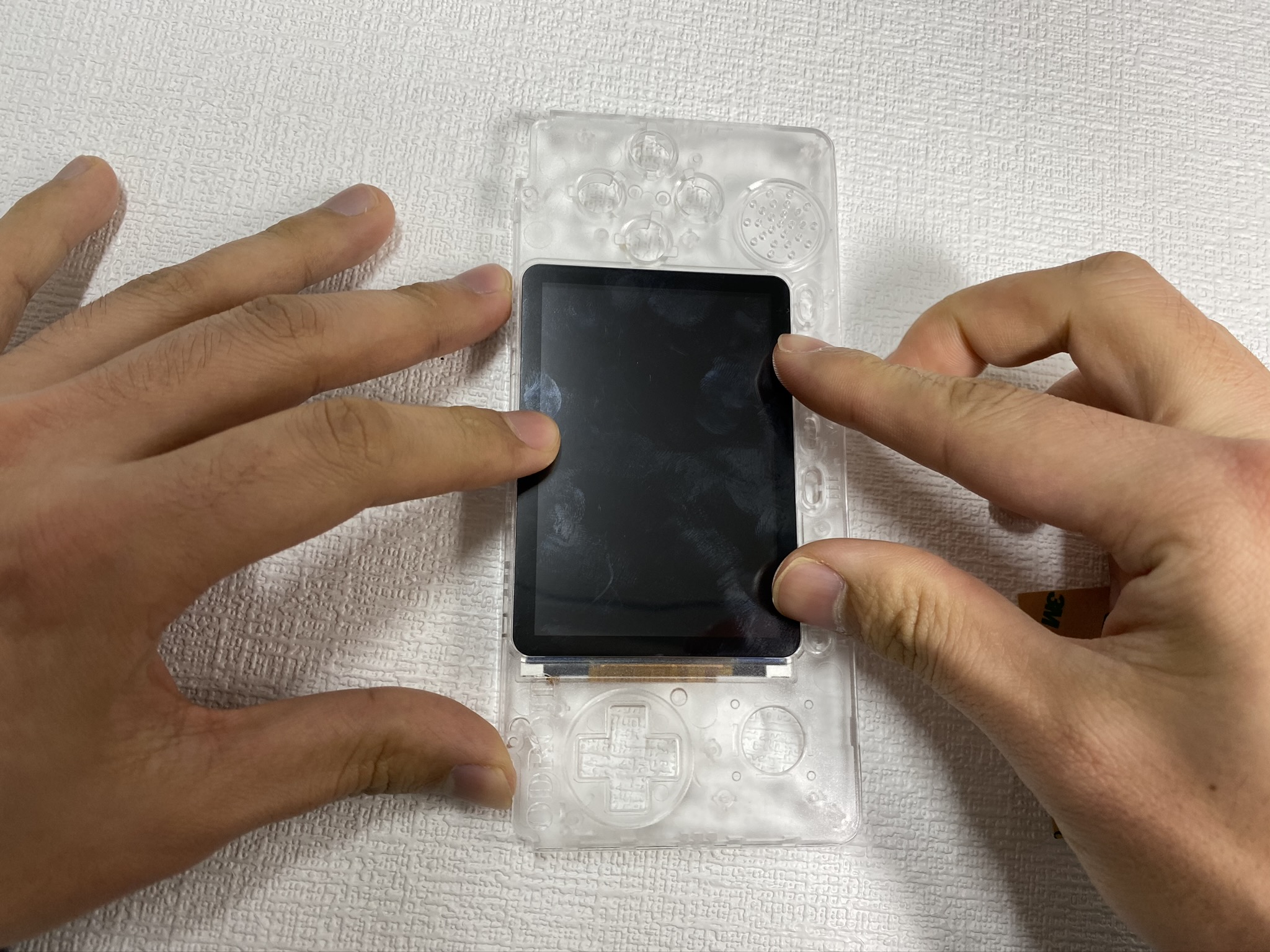
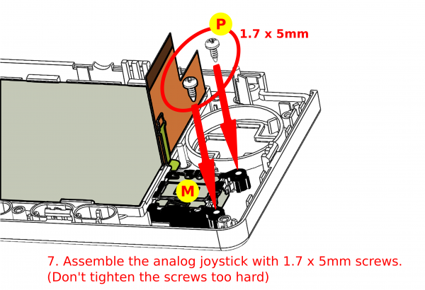
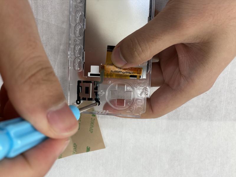
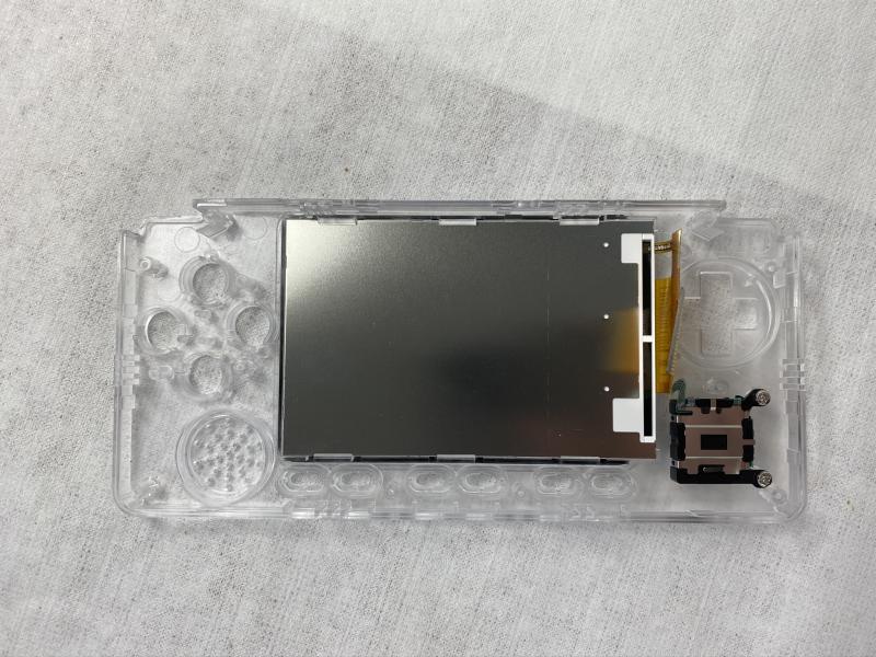
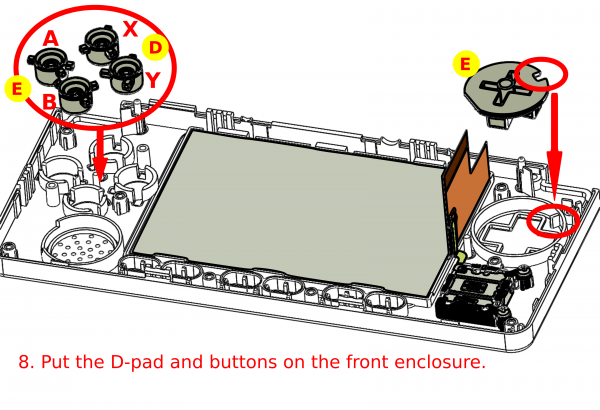 Figura 24: Coloque el D-pad y los botones en la carcasa frontal
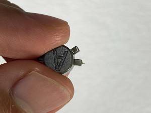
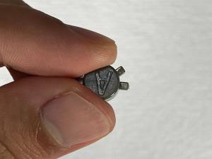
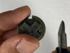 Figura 27 - Primer plano de montaje de los botones
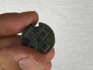
Be the first to comment