March 1, 2020By Moe Long, www.cupofmoe.comLinux, ODROID-XU4
Single-board computers (SBCs) such as the Raspberry Pi might not match up against dedicated server hardware or even most mainstream desktops. Nevertheless, the price-to-performance ratio of maker boards makes these tiny credit card-sized devices extremely competitive. With a small form factor and low price point, development boards are excellent network-attached storage (NAS) devices. One of my favorite home server hardware options for a do-it-yourself (DIY) NAS is the ODROID-XU4. In this article, I can show how one can install Emby Media Server on the ODROID-XU4 treating it as DIY Odroid NAS!
The ODROID-XU4 comes in a typical unassuming single-board computer (SBC) form factor. However, the tiny device hailing from HardKernel sports some beastly specs, particularly for its size. At the heart of the ODROID-XU4 is an octa-core processor paired with a Mali-T628 MP6 GPU with OpenGL ES support. Additionally, 2GB of DDR3 RAMwill aid with multitasking and there is an eMMC module, as well as microSD card slot, for installing a host operating system. For hooking up external devices, the XU4 rocks a pair of USB 3.0 ports and a solitary USB 2.0 port.
Due to its robust processing capabilities, the ODROID-XU4 is an incredibly powerful little SBC that masterfully fuses processing capabilities with energy efficiency. Also, its low price tag means you can use the ODROID-XU4 as a DIY NAS device that will not break the bank.
You would want to build an ODROID-XU4 based NAS for the following reasons:
Affordability,
Octa-core processor (CPU),
Ability to run numerous Linux distros, and
Its energy-efficiency
Why use Emby?
The Emby media-server is a great Plex alternative. It is one of the best media server software options available for the ODROID-XU4. An excellent Plex alternative, Emby allows you to stream your personal media collection such as movies, TV shows, music, and even photos to compatible client devices like phones, tablets, streaming boxes, and smart TVs. Similar to Plex, Emby is really easy to use. However, a robust feature set posits Emby as a better option for power users. Its metadata editing functionality allows you to input correct metadata information. You can add your own custom CSS to the Emby web app to perform actions such as altering the login screen and even deploy custom themes. There is live TV and DVR functionality and local streaming.
Unfortunately, Emby restricts local streaming more so than Plex. For instance, while Plex local network streaming works without a premium Plex Pass, many apps require an app unlock, like Android TV, when using Emby. Nevertheless, Emby is a Plex competitor worth considering and it runs like a champ on SBCs such as the ODROID-XU4.
How to Install Emby Media Server?
Thankfully, spinning up an Emby media server on an ODROID-XU4 SBC is cost-effective and easy to setup. You will need an ODROID-XU4 or the passively-cooled ODROID-XU4Q. Also, you will need a case, power supply, microSD card or eMMC module for an operating system installation, and a Linux-based distribution (distro) such as Ubuntu. Of course, you will have to install Emby Media Server. This project requires an active internet connection, peripherals such as a keyboard and mouse, as well as your personal media like movies, TV shows, and music files. It is easiest to keep these stored on an external device such as a flash drive or harddrive, although you can load them on a microSD card or eMMC where your host OS is installed.
There are numerous Linux distros compatible with the ODROID-XU4. I suggest running a Debian-based distro such as Debian itself, Ubuntu, Ubuntu MATE, Armbian, or DietPi. You could also use OpenMediaVault.
ODROID-XU4 Emby Media Server requirements:
ODROID-XU4 or passively-cooled Odroid XU4Q
microSD card or eMMC module
Linux distro (i.e. Debian, Armbian, Ubuntu, Ubuntu MATE, DietPi)
Emby Media Server software
Media collection (movies, TV shows, music, photos)
External storage device
Peripherals (keyboard, mouse)
Active internet connection
Emby client device (i.e. PC, smart TV, Roku, Android TV box, smartphone/tablet, etc.)
Total cost: About US$62. Normally, the ODROID-XU4 retails for around $62. You can snag one from the likes of Ameridroid, sometimes with some discounts. Any extras will cost more. For a self-contained NAS, check out the ODROID-XU4 and ODROID-XU4Q compatible ODROID-CloudShell2 which features support for up to two 3.5" HDDS or SSDs.
Install Emby Media Server
Assume you have a Debina-based OS installed on the ODROID-XU4. First run an update:
$ sudo apt-get update && apt-get upgrade
Then, install the Emby Media Center. Since it is an Armv7 (armhf) board, you will need to download the appropriate Armv7 DEB (https://emby.media/linux-server.html) file on Debian. With that downloaded, install it using (for a newer DEB version, replace emby-server-deb_4.3.1.0_armhf.deb with the current version):
$ dpkg -i emby-server-deb_4.3.1.0_armhf.deb
If you are running CentOS on the Odroid XU4, you will need to install the Armv7hl Emby app (check the most current version and replace 4.3.1.0/emby-server-rpm_4.3.1.0_armv7hl.rpm with that if necessary):
If you are running Fedora on the ODROID-XU4, you will need the Armv7hl file (you may need to swap 4.3.1.0/emby-server-rpm_4.3.1.0_armv7hl.rpm for the most recent RPM):
With DietPi (a great Debian-based Linux distro that features a modular installation) installed, enter the command:
$ dietpi-software
You will see the DietPi-Software center. Head to Software Optimized > Emby Server and press spacebar to select it. Click tab to press ok, now *** install and click ok. You will be prompted to select if you want to install Emby Server on DietPi, so pick ok.
Add Your Media to Emby
[ Fig 01 ]
Once Emby is installed on the ODROID-XU4, you can add your media. By default, Emby uses the port 8096. On your Odroid XU4, head to http://localhost:8096. Or, if you are using a different computer on the same network as your XU4 board, enter ODROID_IP_ADDRESS:8096 where ODROID_IP_ADDRESS is the address of your ODROID-XU4.
[ Fig 02 ]
At the friendly Emby Media Server setup screen, pick your preferred language then choose a username and password. After that, configure your media libraries. Hit Add Media Library and pick a content type such as Movies, TV Shows, or Music. Now, pick a display name like Movies and hit the plus (+) sign beneath folders to add appropriate media. Configure metadata download information and your country. Now, choose ok and if all is properly configured, hit next. Repeat this process for every content type, then save.
Odroid XU4 NAS Performance with Emby
[ Fig 03 - Groundhog Day ]
I found that the ODROID-XU4 was more than capable of transcoding a single 1080p file alongside a 480p file. Or, you can transcode around four to five simultaneous 480p files. For local streaming, I tested four concurrent 1080p files, but you might be able to run more than that. Regardless, it is a major step up over even the Raspberry Pi 4. On a Pi 4, direct play was fine, but transcoding was completely out of the question.
Should You Build an Odroid XU4 NAS with Emby Media Server?
For an inexpensive, high-performing media server, the ODROID-XU4 is a worthy SBC. It is capable of transcoding and, while it pales in comparison to my Xeon-powered ThinkServer TS140 which can handle four simultaneous 1080p transcodes, it cost a fraction of the price. The fact that a sub-$100 board can handle transcoding at all is mind-blowing. Overall, the ODROID-XU4 continues to impress. I have enjoyed retro gaming emulation on the ODROID-XU4, and as a home server, the ODROID-XU4 truly excels.
March 1, 2020By Moe Long, www.cupofmoe.comODROID-XU4, Tutorial
The ODROID-XU4 is an amazing single-board computer (SBC), and one of the best Raspberry Pi alternatives on the market. Due to its horsepower, it functions better than a Raspberry Pi for a variety of applications including retro gaming emulation. Notably, the ODROID-XU4 with its octa-core ARM processor can handle media transcoding pretty well, particularly for its modest size. Find out how to make an Odroid NAS, and whip up your own ODROID-XU4 Plex media server!
What is Plex and Why Should You Use it?
Plex can be thought of as a DIY (do-it-yourself) Netflix. Whereas Netflix, for instance, lets you stream content from its servers, Plex allows you to take your (legally obtained) digitized media such as movies, TV shows, music files, and pictures, then access them on compatible client devices like phones, tablets, smart TVs, and streaming devices.
However, since its inception, Plex added a slew of cord-cutting features, thereby making it a one-stop-shop for media consumption. In addition to its media server capabilities, Plex now offers web shows, a podcast downloader, Tidal integration, plus free, legal, ad-supported streaming movies and TV shows. There is also the ability to hook up an over-the-air (OTA) antenna for live TV and DVR functionality. Nevertheless, Plex remains focused on its core media server purpose. The rest of its functionality is merely to further appeal to cord cutters, and at that Plex handily succeeds. It is a great way to spin up a media server for streaming your backed up DVDs and Blu-rays, CDs and vinyl, as well as photos to virtually any device you can find.
What is Plex media server: A media server software option for streaming your movies, TV shows, music, and photos to compatible client devices.
Why Build an ODROID NAS with an ODROID-XU4?
There are numerous SBCs on the market. And the ODROID-XU4 remains a top contender. With Samsung Exynos5422 Cortex™-A15 2Ghz and Cortex™-A7 Octa-core CPUs and a Mali-T628 MP6 GPU, as well as 2GB of DDR3 RAM, the ODROID-XU4 packs quite a performance punch into its unassuming form factor. Furthermore, eMMC module support in addition to a microSD card slot lends versatility for operating system (OS) installation. With two USB 3.0 hosts, hooking up external drives such as a flash drive or external HDD is a breeze. The extra throughput and read/write speeds from its USB 3.0 ports will lend an extra boost to its media server functionality.
Octa-core processing
eMMC and microSD card slots
2 x USB 3.0 hosts
Gigabit Ethernet
Plex Install - Build an ODROID-XU4 Plex Server
You can spin up an ODROID-XU4 Plex server pretty easily. For this, you can use pretty much any Linux distribution (distro) such as Raspbian, Ubuntu, or another Debian-based OS. Alternatively, other Linux OSes will work just fine such as DietPi.
You can install Plex in Ubuntu, Raspbian, Armbian, or another Debian-based Distro.
Before proceeding to install Plex, you should run an update:
$ sudo apt-get update && apt-get upgrade
Next, install Plex Media Server for armhf/arm64. For this, you'll need to become root:
With the Plex Media Server repo added, go ahead and activate HTTPS:
$ apt-get install apt-transport-https
Then, perform a repo update:
$ apt-get update
When that is finished, install Plex for the ODROID-XU4:
$ apt-get install plexmediaserver-installer
You should now have Plex running on the ODROID-XU4.
ODROID-XU4 Plex Server Set-Up
Since Plex media server has been installed on your Odroid board, you will now need to configure your server software and add your media. In a web browser, navigate to localhost:32400/web/. Or, if you are using a remote PC, enter YOUR_XU4_IP:32400/web/ where YOUR_XU4_IP is your ODROID-XU4 board's IP address. You can check your IP address using the command line:
$ hostname -I
You will need to perform some basic set up such as creating a Plex account and naming your server. Once you have logged in and picked out a name, hit Next. Then, select the location of your media. I used an external harddrive full of media. Hit Add Library, then choose the library type i.e. movies, TV shows, music, photos, or other videos. Locate the appropriate folder or folders containing your media. Repeat this for each content type, and when you are all done, proceed to the main Plex dashboard.
Odroid NAS Performance - Running Plex on the ODROID-XU4
[ Fig 01 ]
I have run Plex on a ton of different devices, from my Xeon-powered ThinkStation TS140 server to the Raspberry Pi 4. Particularly for a SBC, the ODROID-XU4 is a beast for Plex use. Plex transcoding actually works on the ODROID-XU4, at least for a single 720p or 1080p transcode. Direct play, no transcoding, the ODROID-XU4 can tackle five simultaneous 1080p streams, an impressive feat from such a small board. Indeed, it's a tiny but mighty maker board.
[ Fig 02 ]
With an affordable price point, the XU4 blows many other SBCs out of the water. As a NAS device, the ODROID-XU4 is a superb consideration. Add a CloudShell2 NAS Kit and you can cobble together a DIY NAS with room for two 2.5" HDDs or SSDs. There is even a USB 3.0 to SATA bridge for UAS and RAID compatibility. As such, you can build a completely self-contained Plex media server with the ODROID-XU4.
Plex Media Server Odroid XU4 NAS - Final Thoughts
[ Fig 03 ]
While there is definitely more powerful server hardware available, it is tough to beat the price-to-performance ratio of the Odroid XU4. There is a pretty solid community, and Plex is well-supported. What is most impressive is the XU4's ability to tackle transcoding. Admittedly, it is not able to muster multiple simultaneous 1080p transcodes. However, the Raspberry Pi 4 cannot even handle a single transcode, though non-transcoding is awesome on the Pi 4 which can stream four simultaneous 1080p direct play files. Overall, the ODROID-XU4 makes an ultra-affordable, shockingly competent NAS.
Home Assistant: Automate Your House With Your ODROID-N2
March 1, 2020By Pascal VizeliODROID-C2, ODROID-XU4
Home Assistant (HA) is a home automation operating system with a focus on local control and privacy. HA includes a custom operating system, HA Core, to run the home automation operations and a supervisor to manage everything, keeping it up to date.
[Fig 01 ]It is the most prominent open-source home automation platform worldwide, with over 80,000 active installations and it is translated into 57 different languages. HA was listed in the top 10 most active projects on GitHub in 2019. Every 3 weeks, a new release is built with contributions of over 80 different people. The project is financed by the HA Cloud provided by Nabu Casa, Inc. This is a subscription service offering features like an end-to-end encrypted connection to the home, without any configuration on the user side.
HA is growing very fast, and there are a handful of full-time developers that work on this project together with the community, which helps to support the 1550 different integrations that HA supports.
[ Fig 02 ]The HA Operating System supports a wide range of platforms. From a Virtual Appliance up to various SoC Boards. When the operating system started, three years ago, the idea was to support as many SoCs as possible. However, we soon realized that not every hardware results in a good user experience of the next-gen smart home hub.
We now focus on the SoCs that provide the desired user experience, are prominent and easy to get for the first taste of HA. We have ready-to-use images for each supported platform. To get started, you need to flash our image with Etcher to an SD card or eMMC. This is a one-time process; once up and running, you can use OTA updates via the user or command-line interface.
In the upcoming release of HA OS 4 (short REL-4), we worked hard to improve our support for the ODROID-C2 and ODROID-XU4 boards, and we are also adding support for the ODROID-N2. It is using the mainline Linux kernel (LT 5.4) and u-boot (2020.01) with some backported device-tree fixes from Linux 5.5 and a u-boot fix to adjust the MAC address of the internal ethernet port.
Amlogic S922X, S922D, and A311D are the perfect SoCs for the Next-Gen smart home hub. ODROID-N2 is using the S922X, which makes it an ideal device to run HA on.
Our operating system started its life named Hass.io, as a fork of ResinOS. ResinOS uses Yocto to create an embedded Linux system, however, ResinOS values didn’t align with our “local control and privacy first”. Yocto was tough to maintain for all the different platforms for a small project with limited resources like ours. This leads us to create the HA OS with the focus on local control and privacy first, built from scratch using Buildroot, powered by our previous experience.
Buildroot has helped to simplify everything and made the project easier to maintain by our community. The only goal of the OS is to provide anything that is required to run the Supervisor. This includes things like Docker, NetworkManager, Dbus, AppArmor, and Systemd. We optimized the operating system to have a small footprint by leveraging ZRAM and LZ4/SquashFS to compress the root file system and device memory.
The Supervisor is the brain of the system and runs inside a Docker container. It manages the host functionality, Docker orchestration, and locally attached Hardware. The Supervisor streamlines this into an API, which is consumed by our user interface. The Supervisor allows spinning up additional software, using Docker containers with extended wrapping, called add-ons.
HA comes preinstalled with its own collection of add-ons and a collection provided by the community. It is also possible to add additional add-on repositories to the built-in add-on store. This functionality makes it possible to install the Mosquitto MQTT broker, Node-RED, VSCode, and many other software packages with a simple click. An internal network and service layer ensures a seamless user experience by integrating user interfaces provided by add-ons, into the HA user interface.
[ Fig 03 ]On top of the Supervisor lives HA Core, HA Core is responsible for collecting the data, providing control and home automation. It is the ultimate home automation software, virtually capable of integrating with anything with the, over 1550, integrations it provides.
All these pieces combined makeup HA, which is free and open-source, and built by a great community. Get yourself an ODROID-N2, install HA and join the HA universe at https://www.home-assistant.io!
How To Assemble The ODROID-GO Advance
March 1, 2020By Justin Lee, CEO of HardkernelODROID-GO Advance, Tinkering, Tutorial
One of the best features of the ODROID-GO Advance is that you can build it yourself, since it comes in kit form. This means that you can learn how the pieces fit together, do it as a project with your siblings, friends, or children, and have the satisfaction of playing games on a truly unique device that you built yourself!
To assemble the ODROID-GO Advance, unpack all of the parts and verify them against Figure 1. Be gentle when attaching cables to the PCB, and make sure not to over-tighten any of the screws. Read through all of the instructions, and watch the video, before starting.
Figure 1 - ODROID-GO Advance kit annotated parts diagram
A
USB Type-A Power Cable
J
D-PAD rubber
B
Front enclosure
K
A, B, X, Y button rubber
C
Back enclosure
L
battery sticker
D
Plastic L/R trigger, X, Y, power Buttons
M
Analog joystick
E
Plastic D-pad, A, B Buttons
N
320×480 TFT LCD
F
ODROID-GO-Advance board
O
0.5W speaker
G
3000mAh battery
P
1.7×5 screws 7pcs
H
LCD window
Q
1.7×8 screws 4pcs
I
I ~ VI button rubber
R
Screw driver
Build Instructions
The video at https://youtu.be/FsfpAkKGEXc shows detailed instructions on how to use the kit, and should be used in conjunction with the instructions here to ensure that everything is assembled properly.
LCD assembly
Figure 2 - Fold the yellow tab as shown
Figure 3- Closeup of LCD panel insertion
Figure 4 - Closeup of the yellow tab
Figure 5- Insert the LCD panel as shown
Figure 6- Closeup of LCD panel insertion
Figure 7 - Closeup of LCD panel insertion
Figure 8 - Closeup of LCD panel insertion
Figure 9 - Closeup of LCD panel insertion
Figure 10 - Closeup of LCD panel insertion
Figure 11 - Closeup of LCD panel insertion
Inserting the LCD
Figure 12 - Make sure that the yellow tab is in front of the enclosure
Figure 13 - Closeup of the LCD panel insertion
Figure 14 - Carefully remove the backing of the double-sided tape, remove the LCD protective cover by pulling on the yellow tab, and carefully attach the LCD protector with the exposed double-sided tape
Figure 15 - Closeup of removing the double-sided tape
Figure 16 - Closeup of removing the double-sided tape
Figure 17 - Closeup of removing the double-sided tape
Figure 18 - Closeup of removing the double-sided tape
Figure 19 - Closeup of removing the double-sided tape
Figure 20 - Closeup of removing the double-sided tape
For alternative assembly instructions for the LCD panel, check out the video at https://youtu.be/ShFrKvPcjsE.
Analog joystick assembly
Figure 21 - Assemble the analog joystick with 1.7 x 5mm screws, making sure not to over-tighten the screws
Figure 22 - Closeup of attaching the analog joystick
Figure 23 - Closeup of attaching the analog joystick
Button assembly
Figure 24 - Put the D-pad and buttons on the front enclosure
Figure 25 - Closeup of attaching the buttons
Figure 26 - Closeup of attaching the buttons
Figure 27 - Closeup of attaching the buttons
Figure 28 - Closeup of attaching the buttons
Figure 29 - Closeup of attaching the buttons
Figure 30 - Assemble the power button
Figure 31 - Insert the rubber buttons into the enclosure
Figure 32 - Closeup of inserting the rubber buttons
Speaker assembly
Figure 33 - Insert the speaker into the front enclosure
Figure 34 - Closeup of speaker assembly
Figure 35 - Closeup of speaker assembly
PCB board assembly
Figure 36 - Put the ODROID-GO Advance PCB in the front enclosure
Figure 37 - Insert the 1.7 x 5mm screws
Figure 38 - Connect the LCD, joystick, and speaker cables to the PCB
Note: never raise the joystick connector more than 90 degrees or it will break.
Figure 39 - Closeup of attaching the PCB connections
Figure 40 - Closeup of attaching the PCB connections
Figure 41 - Closeup of attaching the PCB connections
Figure 42 - Closeup of attaching the PCB connections
Figure 43 - Closeup of attaching the PCB connections
Figure 44 - Closeup of attaching the PCB connections
Figure 45 - Closeup of attaching the PCB connections
Figure 46 - Closeup of attaching the PCB connections
Figure 47 - Closeup of attaching the PCB connections
Figure 48 - Closeup of attaching the PCB connections
Figure 49 - Closeup of attaching the PCB connections
Figure 50 - Closeup of attaching the PCB connections
Figure 51 - Closeup of attaching the PCB connections
Battery assembly
Figure 52 - Stick the dual-sided tape on the battery
Figure 53 - Close of the battery tape
Figure 54 - Connect the battery to the ODROID-GO Advance
Figure 55 - Connect the battery to the ODROID-GO Advance
Trigger buttons assembly
Figure 56 - Insert the trigger button keys into the slots, making sure to align them to the left and right side as indicated on the button
Figure 57 - Close of trigger button keys
Back enclosure assembly
Figure 58 - Stick the battery on the back enclosure
Figure 59 - Closeup of battery attachment
Figure 60 - Closeup of battery attachment
Figure 61 - Close the back enclosure
Figure 62 - Press the hook with your finger until it makes a snapping sound
Figure 63 - Closeup of attaching the enclosure
Figure 64 - Closeup of attaching the enclosure
Figure 65 - Closeup of attaching the enclosure
Figure 66 - Closeup of attaching the enclosure
Figure 67 - Closeup of attaching the enclosure
Figure 68 - Closeup of attaching the enclosure
Figure 69 - Closeup of attaching the enclosure
Figure 70 - Assemble the back enclosure with the 1.7 x 8mm screws, being careful not to over-tighten them
Generally, Arduino APIs are used with a microcontroller like an Arduino-UNO, esp8266, etc. These APIs make it easier for people who have used Arduino to control their ODROID GPIO, so I developed an Arduino API layer for ODROID.
There is no need to install Arduino IDE on your PC and you don’t need to connect the PC to your ODROID; just install Arduino IDE and some dependencies into ODROID and write code. When you upload the code, ODROID runs the code on its own. The GitHub repository is located at https://github.com/hhk7734/oduino.
If you already opened an Arduino IDE, close it and reopen the IDE.
odroid-config
Odroid-config is a utility that helps users configure for ODROID easily.
The code is available at the following Github repo: https://github.com/hhk7734/odroid-config
Arduino IDE Setup
Tools -> Board -> ODROID Series
Tools -> Port -> /dev/ttyHK0
Tools -> Programmer -> Bridge
Pinmap
Arduino for ODROID uses a physical location based pinmap. If you have ODROID-N2, the pinmap is shown in the following table.
By default, the Arduino-UNO connects the D13 to the LED. So the constant expression: int LED_BUILTIN = 13; is declared. Connect the LED to the 13-pin and upload the example code and the LED will blink.
March 1, 2020By Justin Lee, CEO of HardkernelODROID-GO Advance, Tinkering, Tutorial
Disassembling the ODROID-GO Advance is fairly straightforward, and involves removing the screws from the outer case and carefully pulling apart the front and back pieces. However, during this process, one of the components is vulnerable to breakage if done imprecisely.
Figure 1 - SW15 can easily be bent during disassembly if care is not taken
Figure 2 - The SW15 component can also become separated from the board during disassembly
Figure 3 - The SW15 component can also become separated from the board during disassembly
Figure 4 - Another view of the board with SW15 accidentally removed
Have you ever wanted to make your own video games? Well you have come to the right place. This tutorial series will show you how to make your own games at a very low cost to you. You can develop them and play them on your own little computer, the awesome ODROID-N2. Wait there is more! You will also gain experience working with Linux, setting up a single board computer, writing code in Java, working with IDE's, and accessing general purpose IO pins to actually control your game. Yes, you heard right, this tutorial series will show you how to control your own game using a breadboard, jumpers, and some switches.
Now I know there are a lot of different game APIs out there, and powerful game development tools like Unity, but often, beginners have to not only learn about video game programming, but also how to program in general, and then also learn how to use the game development tool. That is a lot to learn and can be a bit daunting. Fortunately there are many aspects of game development that are almost universal; like game loops, managing graphics and game resources. Even IDEs are becoming more and more ubiquitous and offer many of the same features and very similar interfaces for software development.
This tutorial series will assume you know nothing about coding and show you how to start from the ground up for building your own development box, configuring it, and writing your own code. Now that is a lot to take in, and a lot to cover so we will be doing a little bit of instruction inside each tutorial. We will not go into a lot of depth on certain subjects. For instance, I will be showing you some code and showing you how to use it and run it but I will not go into depth on the Java programming language, that could take up a whole book on it's own. I will, however, give you some starting knowledge and you can go off on your own and research certain topics as you see fit.
Well that is the gist of it, let’s get started.
Review of the things you will need
Now there are a lot of options for configuring your ODROID-N2 so we will go over what we recommend and also what other configurations are acceptable. The low end configuration we recommend will cost around $120 not including shipping. The higher end configuration will cost around $140. You will need an HDMI monitor or TV to use with your ODROID-N2 development box and a mouse and keyboard. You can use any old USB mouse and keyboard.
Configuration 1: This is the recommended configuration because of the stability and speed offered by eMMC modules. We recommend using a decent sized eMMC module as the operating system boot memory module and using a microSD card for file backups and storage. There are links above to different sized eMMC modules and microSD cards. You can also choose between an ODROID-N2 with 2GB or 4GB of RAM. The 2GB version will run fine but if you want to go all out the 4GB version can only be an improvement. We recommend using at least a 32GB eMMC module as the OS boot memory module and having anywhere from 16GB to 64GB of backup storage in the form of a microSD.
Configuration 2: This configuration will work fine but doesn't have the performance and stability benefits offered by using an eMMC module. In this setup you would use one microSD card as both the boot memory module and for all file storage. If you go this route we recommend you buy a second microSD card to backup your files to and get a microSD to USB converter so that you can access the files on any computer and the ODROID-N2 itself.
There is a mention at the top of the page for a really great ODROID-N2 case available from Hardkernel. I would think about getting 2 of them. We will be accessing the GPIO pins on the ODROID-N2 board and you have the option to open an access port on the case for easy access to the pins. However, you may want to keep the device completely closed in certain situations and having a second case will allow you to easily change tops so you can use o6ne for GPIO and the other to keep the device fully closed and protected.
So for less than $150 you will have a fully functional Linux based computer to use as a development box for games, if you have an HDMI screen/TV and a USB mouse and keyboard. If you need to buy those remaining parts the price will vary but you can certainly be developing for under $350 if you shop around for a great price on a screen/TV.
OK, so now that we have that part out of the way let us get started setting up the operating system on the eMMC module or microSD card. I will provide instructions for MS-Windows, Mac, and Linux for each one. It is actually very simple and the process is almost exactly the same for both. You will need access to another computer to do this step but I will also show you how to use your ODROID-N2 to setup a new eMMC module or microSD card for the ODROID-N2.
If you do not have access to another computer to prep your eMMC module or microSD card you will have to buy one of the pre-installed eMMC modules or microSD cards from Hard Kernel, listed above. We recommend that you get the 16GB ODROID-N2 microSD card and use it to setup a custom eMMC module that we will use for this tutorial series. You can also get the Hard Kernel 16GB microSD card and use it to setup a larger microSD card as the boot memory module. With these options you should be able to get your dev environment up and running without access to another computer.
Build your ODROID-N2 Computer
In this step we will put together the ODROID-N2 and get it ready to create our custom boot eMMC or microSD memory module. Seating the single board computer and assembling the case is very simple. This is one of the best case designs I have seen in a while. You will not be pushing and pulling and hoping you do not crack some plastic catches at all. Simply seat the ODROID-N2 on the metal base of the case. This also acts as a heat sink, ingenious! Gently tighten up the screws until they are firmly tight, do not over tighten them. A good firm setup is what we're looking for here. Let us take a look at the case and board.
Figure 1
Next slide on the case front. Make sure you have the case front plastic guides lined up with the little metal ridge on the case bottom.
Figure 2
Now if you have opted to purchase two ODROID-N2 cases then you will want to break out the small GPIO panel on the top of the case's back. This is the longer case top that has a long "door" on it. This will allow you to work on the GPIO section of this tutorial with a protected ODROID-N2. If not, do not worry, we will just leave the remaining case top off for now. Be sure not to have any drinks or cats around your ODROID-N2 while it's exposed.
We recommend that you purchase a bootable microSD card from Hardkernel and use it to create the custom Linux OS we will be using in this tutorial series. When I say custom I only mean that we can choose which version of Linux OS images available for the ODROID-N2 we want to use and we will also get experience building bootable eMMC modules and microSD cards.
Figure 3
The picture above shows the ODROID-N2 with a Hardkernel bootable microSD card and the boot device switch set to the MMC setting. Note that the MMC setting is used for both eMMC modules and a microSD card. The board gives higher priority to eMMC modules than microSD cards. In this way if you have both setup it will always try to boot the eMMC module first. I'd like to reiterate that we're purposely creating our own bootable eMMC module or microSD card because we want to be able to do so any time we want. Obviously we already have a bootable microSD card, the one from Hard Kernel, but we're only using it as a jumping off point to using the ODROID-N2 for creating our own bootable media.
Now that we have the computer setup let us fire it up and get into our Linux desktop. We will be locating and downloading a specific Ubuntu Linux image to write to our eMMC module or microSD card, whichever path you decide to take. If you have access to a computer and are not building your custom boot memory module on the ODROID-N2 just follow the steps using your favorite browser and I will be sure to show you how to write to your storage device of choice on Windows or Mac.
Figure 4
You will need an internet connection for this part. If you do not have access to an internet cable to plug into your ODROID-N2 then purchase a WIFI module, links above, and you should be all set. If you're not sure which one to get just load up the page for that product and see what types of WiFi each module supports. I have found that the cheapest, WiFi Module 0, works just fine and does not take up a lot of space around the ODROID-N2's USB ports.
Simply plug the module into an available USB port while you have your system booted up and running Ubuntu MATE. You should be able to select the WIFI icon in the top right corner of the screen. Doing so will give you a list of available WIFI networks in your local environment.
Figure 5
Select your WiFi network and you will be prompted to enter in any authentication information required by the WiFi end point. The screenshot below depicts a similar prompt you will encounter when connecting to WiFi.
Figure 6
Now that you have got your internet connection configured, open up a browser and make sure you can access the internet.
Figure 7
Click the wiki link at the top of the page.
Figure 8
Or you can jump right to the destination by navigating your browser to the ODROID Wiki (https://wiki.odroid.com/). Select the ODROID-N2 option from the side navigation bar. Select os_images then select ubuntu. You should see a list of dates, click the 20190812. Choose a mirror from the list of mirror sites, I use the East Coast Mirror (https://east.us.odroid.in/ubuntu_18.04lts/) because it is closer to me.
Once on the mirror site you will have to navigate to the ODROID-N2 OS image, click the ODROID-N2 link.
Figure 9
Next click the ubuntu-18.04.3-4.9-mate-odroid-n2-20190812.img.xz link. It may take a few minutes for it to download because it is around 1GB in size so get up, stretch, walk the dog, feed the cat, or do whatever it is you want to do to kill a few minutes.
Figure 10
Also, like any good cooking show we have the meal we are making already prepared so a direct link to the east coast mirror OS image we want is, ubuntu-18.04.3-4.9-mate-odroid-n2-20190812.img.xz. Once your download has completed you may receive a window popup like the one shown below. This has something to do with Ubuntu MATE detecting the file type and thinking you want to update your current eMMC module or microSD card.
Figure 11
Select Cancel and close the window behind it so that you're back at the browser. Now that you have got a copy of the OS image downloaded it's time to move onto the next step. Read below to choose your path, the recommended path has the best performance and reliability but may be slightly more expensive. Choose wisely.
If you have a bootable Hardkernel microSD and plan to use an eMMC module (recommended) then proceed to Section 4.
If you have a bootable Hardkernel microSD and plan to use a microSD card then proceed to Section 5.
If you have a computer and are building an eMMC module or microSD card:
Follow along with Section 4 for eMMC modules, or Section 5 for microSD cards
and you will find information on how to build the boot memory module using Windows or MacOS at the bottom of that section.
Setup your ODROID-N2 with an eMMC Module
To prepare for this step you will need your eMMC module and a Hardkernel eMMC to USB adapter. Lay your eMMC module down on a dry static free surface so that the chip side is facing up.
Figure 12
Note the white notch in the corner of the eMMC module. This will line up on the same side, left or right, as the white circle (or notch) on the eMMC to USB adapter. It does not line up with the exact corner just the side.
Figure 13
Carefully place the eMMC module's little black connector onto the eMMC to USB adapter's little black connector. You can kind of roll the eMMC module onto the adapter and line up the connectors. Gently press down and the two connectors will gently and slightly snap together. that is it, you have successfully mounted the eMMC module onto the adapter. Now plug your eMMC to USB adapter into your ODROID-N2, as shown below.
Figure 14
You are now ready to start writing an OS image to the eMMC module, which we will cover in the next few steps. Feel free to skip any microSD steps that do not apply to you. You can always come back and look up any info you need. I will cover a few different ways to write the OS image to the memory module using different environments. The process is the same for an eMMC module or a microSD card.
Setup your ODROID-N2 with a microSD Card
To prepare for this step you will need your target, new, bootable microSD card and a microSD to USB adapter. Simply plug your microSD card into the USB adapter and then plug the adapter into your ODROID-N2.
Figure 15
That is it! Now you're ready to start writing an OS image to your microSD card. I will cover a few different ways to write the OS image to the memory module using different environments. The process is the same for an eMMC module or a microSD card.
Writing to your Memory Module using Linux, Windows, or Mac
This step will cover writing to your eMMC module or your microSD card. At this point the process is the same for both. If you have connected your eMMC module or microSD card, please eject it. We are going to get the device in Linux for the memory module and we want to be able to detect that new device so we do not accidentally write to our Hard Kernel bootable microSD card.
For this step you are going to need to open up a terminal. On the top left hand side of the screen bring up the list of applications, and utilities. Click on System Tools, then locate the MATE Terminal program entry as depicted below. Click it and you will have a terminal window to work with.
Figure 16
In the terminal type the following command:
$ sudo fdisk -l
Note the list of drive devices that are shown. Now connect your memory module and run the command again. Note the new entry in the list and write it down or copy and paste it into a text document. This step verifies that we will be writing to the proper memory module. For the purposes of writing this tutorial let us assume that the device is dev/sdx. Next we will unmount the device by using some sweet terminal commands.
Unmount the partitions by running:
$ sudo umount /dev/sdx*
It may give an error saying the disk is not mounted - that is fine. Now we will write the contents of the image file onto the SD card by running the following command.
If your file has a .img.xz extension instead of a .img extension you can right-click the file in MATE using normal file operations and extract it to a .img file. You can also use the following command to do both operations in one step.
Remember in this case the /path/to/file/your_image_file_name.img.xz or /path/to/file/your_image_file_name.img is the path to the ubuntu-18.04.3-4.9-mate-odroid-n2-20190812.img.xz file we want to write and /dev/sdx is the device name we figured out earlier. You can navigate to where the file is located using the MATE desktop. Right-click the window and select the Open Terminal command to open a terminal at the location of the target file.
In this case your terminal commands would be:
Let the operation run to completion and you will have a fresh new bootable memory module to use on your ODROID-N2. What is more you can use these steps to try different ODROID-N2 operating system images. Just look around the wiki page (https://bit.ly/3a0xyXe) for other OS options to try. For our purposes we are ready to move onto the next step of this tutorial. I will take a moment to demonstrate other ways to write the image to the memory module. It is important to note that the eMMC module and the microSD card behave the same at this point. Linux just views them as a memory device to write to.
If you are working on your ODROID-N2 you can use a gui method to write the image to your memory module of choice. Once the image file has finished downloading find the file in your Downloads folder and right-click on it.
Figure 17
Select the Open With Disk Image Writer option. You should see a window pop-up similar to what is shown below.
Figure 18
the proper destination to write the image. ALERT: Be very careful here, make sure you are choosing the target memory module and not the boot SD card!
Writing an OS Image on a Mac
To write the OS image file on a Mac we recommend getting a great piece of free software, Balena Etcher (https://www.balena.io/etcher/). You could also probably run the Linux commands listed above in a terminal on a Mac but let us try something new. Download and install Balena Etcher. The software handles writing .img.xz files so you do not have to worry about decompressing the OS image. Locate your OS image file.
Note: The screenshots below show a different file being written then the one we are working with. The process is the same, no worries.
Figure 19
Next, fire up Balena Etcher and answer any prompts for higher privileges that might pop up.
Figure 20
Double check that you are indeed flashing the correct device and that it is the correct approximate size!!
Figure 21
Start flashing the device and wait for the process to complete.
Figure 22
Writing an OS Image on Windows
To write the OS image file on a Mac we recommend getting a great piece of free software, Win32 Disk Imager (https://bit.ly/2VqBCMa). Now if you are running Ubuntu Linux under Windows 10 you could also probably run the Linux commands listed above in a terminal. You could also install the Windows version of Balena Etcher and follow the directions for that software listed above. I want to show you a new way so that you have a bunch of options and tools you can use to make your own bootable memory modules. You will have to decompress the .img.xz file before we can write it to the memory module. Get a free copy of 7-Zip (https://www.7-zip.org/). Install it and use it to decompress the .img.xz file you should have a nice fresh .img file in a few minutes.
Once your .img file is decompressed and ready to use, open up Win32 Disk Imager and navigate to the .img file you want to write to your microSD card. ALERT: Be sure to select the proper drive letter to write to!! If you have any doubts just eject the microSD card and take note of which drive letters go away. Any card, especially if it has a bootable OS in it, will mount as two drive letters. It is ok to simply choose one of them. The screen shot below shows Win32 Disk Imager in action, it is being used to write a different .img file, just ignore that part.
Figure 23
Once you have everything setup click the Write button at the bottom of the window and let the software do its thing. Be careful that you click the correct button. It can become confusing at times which direction the read or write operation is going, especially if you have done a few cards in a row using different operations. There will be some hint text that will explain what the button you're about to click does. I always read it and double check that it is indeed what I want to do. Configuring Your Dev Environment Now that we have created a new custom bootable eMMC or microSD memory module, whichever you choose, we have to update the OS and install some software before we can begin developing. Boot up the ODROID-N2 with your new memory module and put the Hardkernel bootable microSD card in a safe place. First let us update the operating system and software. We will do this two different ways. The first will use the MATE desktop system tools. Find the Software Updater tool under Menu -> Administration -> Software Updater.
Figure 23.5
Click the Update button and let the process complete. Sometimes an update may require you to hit a button so it's a good idea to keep the window visible and also have the details visible. You should see a window like the following while the update is running.
Figure 24
Once that is complete we will run an update from the command line. This step is more or less the same thing as what the system update tool is doing but it is good to know how to run an update from a terminal so let us do it. Open up the terminal like we did earlier in the tutorial and run the following commands. The default superuser password is odroid. Copy and paste the following command in the terminal window and hit enter.
Once that is done we will want to install some software and we can get most of it done right from the terminal. We're going to install gparted, for partition and drive management, gimp, for image management, default-jre, so we can use the Java runtime environment, and chromium-browser, to add a Chrome browser to the system. Copy and paste the following command in the terminal window and hit enter.
Click the download button and you will be brought to a screen with a list of versions. Go to the latest stable version and click the download button as shown below.
Figure 26
This will take you to a page with a few different links for the version of netbeans you selected. We will want to download a zipped version of the binary files. Click the binaries link and let the IDE download.
Figure 27
Go to the Downloads folder and copy and paste the zip file into a new folder named install_zips, create this folder in your home directory. Once the file is done copying over, unzip it by right-clicking the compressed file and selecting the unzip menu option. Create another new folder in your home directory named applications. Move the uncompressed version of netbeans into this directory. Open the folder, find the bin folder, open it, and right-click on the file named netbeans. Choose the “pin to desktop” option. Now we have a link to open our netbeans IDE. But wait, it looks, well rough. Let us grab a good looking icon for it. Navigate your browser to https://commons.wikimedia.org/wiki/File:Apache_NetBeans_Logo.svg. Save the netbeans icon file from the page that loads up.
Figure 28
Figure 28 ]
Right-click on the desktop shortcut for netbeans. Click on the icon and find the new netbeans icon you just downloaded. Choose it to be the icon for the desktop shortcut. Now we have a proper looking IDE shortcut. Open up the netbeans IDE and allow the IDE to install any modules it needs. You may also have to do this when opening a new project for the first time, simply allow the IDE to install the modules it needs.
Figure 29
Setting up a Swap Partition
In this step we will turn on a swap partition and set up our ODROID-N2 to always enable swap space on boot. This can help us with the IDE and other memory needs we will have when writing games for the ODROID-N2 on the ODROID-N2. First we will check if we have any swap space enabled. Run the following command in the MATE Terminal, Menu -> System Tools -> MATE Terminal. You may want to right-click the menu option and click pin to desktop so that you have a quick shortcut to the terminal when you need it.
$ sudo swapon --show
If there is no text displayed you do not have swap space enabled. If you do see some information printed then you have swap space enabled and you can skip the rest of this step.
Create a new swap file on the root of the boot drive by running the next command.
$ sudo fallocate -l 1G /swapfile
Set the permissions on the swap file to be secure.
$ sudo chmod 600 /swapfile
Enable the file as a new swap file.
$ sudo mkswap /swapfile
Turn on the swap file.
$ sudo swapon /swapfile
To enable the swap file on every boot edit the fstab file and add the following entry, like so.
$ sudo nano /etc/fstab
Copy and paste the following line at the bottom of the file's current contents.
/swapfile swap swap defaults 0 0
Give the system a reboot by running the following command, sudo shutdown -r now, and bam! We now have an active swap partition.
When the system comes back up you can check that the swap file was enabled by running, sudo swapon --show. You should see an entry print out after running the command. If not, go through the process again and make sure you run the correct commands in order.
Mapping Specific GPIO Pins
In this step we will use the terminal and our breadboard to figure exactly what number the GPIO pins, as they are expressed on the breadboard, are. Now sometimes you can check the documentation to see where each pin is, but depending on the OS and how it works you might find yourself in a situation where the pin numbers aren't matching the documentation. Plus it's fun to hook up an LED to the ODROID-N2 and get the light to blink.
Now you will have to connect your breakout breadboard to the ODROID-N2. Simply plug the connector onto the GPIO expansion pins on the board. Make sure it is facing the correct way, the red stripe on the ribbon cable should line up with the side of the GPIO pins that have labels 1, and 2.
Figure 30
We are going to setup a simple circuit using 1 resistor, 1 LED, and 3 jumpers using the breakout breadboard tinker kit from Hardkernel. We're going to setup the following simple circuit. Follow the image and diagram below. Your pin may be different. I'm using pin number 488 which maps to position 7 on the breadboard.
Figure 31
Figure 32
A simple circuit diagram is as follows. The circuit serves two purposes. One, it allows for the pin voltage to drive the LED. This is handled by the first branch of the circuit. Two, it allows for the pin voltage to be driven by a button. This is used to mimic input from a gamepad.
Figure 33
Follow the images and diagram and set up a similar circuit on your breadboard. Once it is ready we're going to run a script to locate some workable pins.
Download the following GPIO scripts (zip) file, https://bit.ly/32vO2Ek. It has multiple scripts for working with the GPIO pins.
Once the file download is completed, decompress the zip file and move the btn_test, btn_prep, and pin_finder scripts into the home directory. Clean up the download folder by moving all the zip files into the install_zips folder we created earlier. This will give you a backup of all the files you need for this tutorial.
Next we are going to query the GPIO pin files to get an idea of what numbers our Linux OS has assigned to the pins. This will give us a range to work with. We're going to be running some tests to figure out which pin is associated with what GPIO number. Run the following command to see the GPIO pin numbers.
$ sudo ls /sys/class/gpio/
You should see certain numbers next to the GPIO chips found. These indicate starting pin numbers and can be an indication of a pin range.
You will see different numbers but what they indicate is a range of pin numbers from 64 to 128 and possibly from 128 up to some unknown number. This will give you an indication of what GPIO numbers to use when you start looking for matching pins.
Now, open a terminal and run the following command from the home directory, nano pin_finder. All the files are setup to work with pin number 488 by default. This may work for you but you should still complete these steps so you know how to find more of your own pins. Edit the text at the top of the file, TMP=488, and change the number to one of the numbers in the range you identified previously. Or you could just move up one to 489 and try that. Write and save the file, Ctrl + O + ENTER, followed by Ctrl + X. Run the script with the following command.
$ sudo ./pin_finder
The script will toggle the high and low value of the target pin. Move connector #1 from pin to pin, waiting for 2 seconds at each spot to see if the LED flashes. If it does you have found the pin location that matches the Linux GPIO pin number.
Figure 34
When you find one blinking pin, write down the position on the breadboard and the pin number used to find it. Make sure to exit the pin_finder script with Ctrl + C when the LED is off. If you miss the timing just start the script and try again. Open the btn_test with the command, nano ./btn_test. Edit the line at the top of the file and enter in the number of the pin you have found. Write the file and exit with Ctrl + O followed by Ctrl + X. Run the btn_test script like so, sudo ./btn_test.
While the script is running, toggle the push button and you should see the output change from 0 to 1 and the LED turn on and off. The image below shows the terminal output during this process.
Figure 35
Setting up a Service for GPIO Permissions
In this step we will quickly setup a service in Linux that will open up the GPIO pin you have located to the odroid user so that we do not have to type sudo every time we want to use it, and so that our Java program can access them also without being required to run the sudo command.
Edit the btn_prep script using nano as we have done before. Change the number at the top of the script to the GPIO number you located with the pin_finder script.
Open a terminal and run the following commands to set the permissions for the GPIO button prep files. You should have a file named btn_prep and custgpiosvc.service in your home directory.
Next we will copy the btn_prep script to the /usr/bin/ directory. Run the following command in the terminal. Make sure you are in the home directory. If you need to get back to the home directory run these commands,
$ sudo cp ./btn_prep /usr/bin/
Now we will install the systemd service so that our system will set permissions to the GPIO files so that the odroid user can access them without running the sudo command. This will make things easy for us to access the pins from Java.
Check to see if the service is up and running with the following command:
$ systemctl is-active custgpiosvc
You should see the word “active” as output. To run the service each time the system boots up you will have to run, systemctl enable custgpiosvc. Now give the system a reboot, sudo shutdown -r now.
Setting Up Projects in Netbeans
In this step we will load up the Java project we need into the Netbeans IDE and make some slight configuration changes. First download the version of the project we will need for this tutorial. This project will be updated and different as the tutorial series proceeds so expect to download a similar project file in the future if you follow along.
The project includes a lot of Java files and we will go over them in a future tutorial but we're going to focus on a small project for interacting with the ODROID-N2's GPIO pins. I will do a more in depth review of code in an upcoming tutorial. And we will go over the game API, also in an upcoming tutorial, because we're going to be working with it to build some games!
Unzip the project after it finishes downloading. Copy the original zip file to the install_zips folder. Move the resulting project directory to a new folder in your home directory. Name the folder netbeans_projects. Now fire up netbeans and open the project by clicking the File -> Open Project menu option. Navigate to the netbeans_projects folder you created and choose the MmgGameApiJava_v0-5-0 folder. The project will load up in netbeans, allow netbeans to install any necessary modules if it pops up and asks to do so.
We are going to make sure the project has one slight configuration change. Right-click on the project and select the properties option similar to what is shown below.
Figure 36
Make sure that the Build -> Packaging -> JAR File property is set to the following, dist/MmgGameApiJava.jar as shown below.
Figure 37
We are all ready to run our Java programs and demonstrate Java connection to Linux GPIO pins! This was a long detailed tutorial to setup our environment. I hope you learned a lot going through it, you have certainly accomplished a ton. We're going to be using this setup to create some Java games for the ODROID-N2 on the ODROID-N2 and use the GPIO pins to control the game with a simple game pad of sorts. This tutorial was the first step.
Reading GPIO Pins with Java
In this step we will tie everything together and read the status of a GPIO pin using Java, very cool. Go to the project you just loaded in netbeans, MmgGameApiJava. Expand the Source Packages section, select the com.middlemind.OdroidGpio package and expand it. Select the OdroidGpio.java file and open it.
Figure 38
Change the GPIO pin number next to the new GpioPin lines. There are six of them to handle a 4 direction D-Pad and 2 input buttons. For now though, set the first number, 488, to the GPIO pin number you located yourself with pin_finder. Once that is done right-click on the MmgGameApiJava project and select clean and build. Open a terminal and navigate to the JAR output directory using the following command.
$ cd ~/netbeans_projects/MmgGameApiJava_0-5-0/dist
Make sure there is a new MmgGameApiJava.jar file in the directory by running the command, ls -al ./MmgGameApiJava.jar, in the terminal. Get ready to run the program, while it's running we are going to toggle the LED and see what the Java program does. Make sure your circuit is setup to work with the pin number you chose, check your notes from the pin_finder step. When you are ready, right-click on the OdroidGpio.java file and select Run file, from the menu.
While the program is running press the button and hold it for a second or two, you should see ProcessAPress in the output window when the button is pressed as shown below.
Figure 39
That wraps up our first tutorial in this series: reading the status of GPIO pins in Java running on your own personal ODROID-N2 Linux computer. That’s a good start and a great place to end this first tutorial. Stay tuned!
Software and Scripts
The software and scripts used in this tutorial can be downloaded at the following links. There are also links provided in the tutorial at the step where they are needed.
GPIO Scripts (https://bit.ly/2HUJXA1)
Netbeans IDE Project v0.5.0 (https://bit.ly/2TguWxy)
March 1, 2020By Tobias SchaafGaming, ODROID-GO Advance
The recently released ODROID-GO Advance has a lot to offer for ODROID fans, and retro gaming enthusiasts. The design of the ODROID makes it perfect for retro gaming and the build in gaming controls are perfect for this purpose.
Still, the board itself can do so much more and we’re lucky to have drivers for nearly any purpose, so I want to look into some alternatives besides emulating retro consoles and test what is possible on a Desktop for the ODROID-GO Advance. I want to test how other applications can be controlled without having to attach a mouse or keyboard all the time, and find out whether using the gamepad controls for input is intuitive for these games.
Requirements
For my test run, I used my Debian Buster image that I released some time ago. I also installed a MATE Desktop on top of it to have a desktop environment. I will make heavy use of a tool called antimicro which will be the basis for all my controller mapping. The programs and games I use either come from my repository or directly from Debian.
Desktop scaling
Some of the applications I want to run require a minimum resolution of 640x480. Since the ODROID-GO Advance has only a resolution of 480x320, we have a problem with these. Luckily for us, X11 supports scaling and allows us to “virtually” increase the size of the Desktop by scaling the output image accordingly. Using the following command, we can get a virtual desktop with the dimensions of 720x480:
$ xrandr --output DSI-1 --scale 1.5x1.5
This command gives our desktop a size of 960x480 (four times the size of the original desktop):
$ xrandr --output DSI-1 --scale 2x2
Because the picture is scaled everything gets a lot smaller, which in return makes things like text much harder to read, so if you are having issues with very small sized text, this may turn out to be a problem for you.
Antimicro
Antimicro is a tool that allows you to map controller buttons to any type of action you want. It can be that with the press of a button, you press a single key on your keyboard instead. For example, when you press D-pad UP, you press the UP key on your keyboard. It can also be a combination of keys. For example, if you press the button I on the ODROID-GO Advance, you do an ALT + F4 on the keyboard instead.
It can even be an entire series of keystrokes in a row, instead of at the same time. For example, like for Quake 2, you could define a button that first triggers a “~” to open the cheat menu, then types “give all” followed by the ENTER key and at last does a “~” again, all with the press of one single button. You can even map mouse events, like moving the mouse pointer or left and right mouse button to buttons on your gamepad.
I guess you understand how powerful this application can be to help configure your games and programs to run only with the ODROID-GO Advance gamepad controls rather than an attached mouse and keyboard. For this, you need to install antimicro-odroid. Note that there is also an antimicro directly from Debian, but it requires QT5 which is currently not configured correctly on arm64, therefore please use the antimicro-odroid package instead.
Figure 1 - Antimicro running on the ODROID-GO Advance mapping mouse movement, buttons and arrow keys
The UI from antimicro is actually quite big and requires you to scale the desktop 2x2 in order to fit.
Firefox
Let’s start off with some applications instead of games. Firefox as a web-browser runs ok on the ODROID-GO Advance. I used just a basic setting in antimicro that maps the analog-stick as a mouse pointer, L und R as mouse buttons and the D-pad as the arrow keys.
I could map more buttons like F11 for full screen ESC to escape out of a fullscreen video or something similar, but I opted not to. Using 2x2 scaling is actually a nice size and you have a good amount of detail on the screen, but testing the ODROID forum as a option for reading some text the experience was not very good.
With 2x2, the text is way too tiny to really read anything. So I opted for 1.5x1.5 scaling instead, and although I lost some space, it was good enough to go through the threads on the forum and read them. Using the D-pad for scrolling up and down also made it quite easy to navigate and for the rest I could use the mouse pointer.
The downside, of course, is that you don’t have any input. I could have used an on-screen keyboard, but that would cover most of the screen, so I abandoned that idea, and instead tried something that could be easier to use through navigation and ended up setting on YouTube. It’s quite usable, since you navigate nearly entirely via mouse, and when you double click a video, it nicely fills the screen and turns your ODROID in a nice little video player. I was actually quite surprised that videos up to 720p are working, but since it’s stressing the CPU a lot, I suggest using 480p, which is also closer to the actual screen size at 1.5x1.5 scaling. In fact, the speaker was performing quite well too, and the sound of music videos and even a 4-hour Looney Tunes special was good.
Figure 2 - Youtube on the ODROID-GO Advance
Figure 3 - The ODROID-GO Advance is a nice video player on the go
There was one downside though while testing this, in that when a video was playing the navigation through antimicro, it seemed to be delayed and the mouse pointer was sluggish. I compared this with using a real mouse, but the issues did not happen with a real mouse, so it seems that the high CPU usage of the video affects antimicro and can cause slow downs in the mouse pointer emulation. It did work, but it was just somewhat delayed.
Clementine
Clementine is my favorite music player for Linux (and even on Windows in the past). Running it on the ODROID-GO Advance was very easy, and using antimicro to navigate it with a mouse was very simple. You can easily add your favorite music stations and playlists, and then use the ODROID simply to navigate between your music, audiobooks, or whatever you put on there. The CPU usage is very minimal, using only about 10 to 15% CPU capacity on one core while playing an Internet live stream. With this, you can turn your ODROID into a mobile music player. Add a bluetooth module, turn off the screen, and you can listen to music for hours and hours.
Using antimicro is to navigate here is very easy and intuitive. You can easily map a bunch of buttons to navigate just a single button click:
F5 – Previous Track
F6 – Pause
F7 – Stop
F8 – Next Track
CTRL + M – Mute
CTRL + Q – Quit
Mapping these on I to VI for example gives you easy access to your control through your playlists.
Figure 4 - Clementine with 1.5x1.5 scaling, works as well in 1x1 and 2x2; just pick which one you like the most
Games
Ok let’s stop with the boring applications. I guess you get the idea: everything that works fine just with input of mouse or arrow keys still works perfectly fine on the ODROID-GO using Antimicro. You can setup key combinations or map buttons for extra stuff like on the music player clementine, but what I really want to know, how is gaming working here?
Alien vs Predator
This fast-paced action shooter is no problem for the ODROID-GO Advance. It was a little bit hard to configure at first, but due to some changes in the code that I made, it works perfectly on the ODROID-GO Advance.
You need to run this game without scaling (1x1), or else you will only be able to run it in window mode, while in 1x1 you can run it in full screen mode, which looks amazing. The game itself though is hard to control, especially since I come from a PC gaming background with little experience. Playing a first-person shooter with controllers was hard for me to find a comfortable way to play. You need one button for the key combination ALT + Enter as the game starts in window mode, and it needs to be switched to full screen mode in order to capture the mouse pointer correctly.
My button layout was as following:
D-pad – Arrow Keys
Analog Stick + L and R – Mouse
B – Space (pulling switches)
A – RSHIFT (jumping)
Y – RCTRL (for crouching)
X - “]” for cycling through weapons
I – ESC (menu)
II – free
III - “.” (throwing flares, cloaking)
IV - “/” (switching view modes – Predator)
V – free
VI – ALT + Enter (switching full screen mode and back)
The two free buttons could easily be configured with one of the many other functions keys in the game: zoom for example, or throwing disc recall. Depending on your needs, these keys will be used up very quickly.
Figure 5 - AVP looks gorgeous on the ODROID-GO Advance
Figure 6 - Cloaked as a Predator on the hunt for Humans
The overall gaming experience is rather mediocre in my opinion. The layout works, but since you need to switch between analog stick and to walk and adjust your sight, it’s not very easy to do this quickly. While playing as a Predator, whose specialty is stealth and sneaking, this is fine, but fast action scenes with the Marine or Alien are nearly impossible to pull off (or maybe I’m just really bad at this kind of control scheme). I wonder if replacing D-pad left and right with mouse left and right for turning would already improve gameplay a lot. The strafing is not very helpful either.
The gameplay is very fast and fluent, and I haven’t experienced any lagging at all, so technically nothing stands in your way to play it once you learn how to control it. Overall, it was a nice experience.
Corsix-TH (Theme Hospital Clone)
The funny simulation / management game Corsix-TH runs quite well on the ODROID. It uses SDL2, and with that, adjusts automatically to the display size you have. So it will work no matter if you use 1x1, 1.5x1.5 or 2x2. In fact, it probably always looks the same.
The menu and text is quite hard to read since the font is quite tiny. The game is rendered in 640x480 and then scaled to the resolution you have. Overall, it’s an interesting experience, and quite playable with just the ODROID-GO Advance’s gamepad as an input. Using the analog-stick and L+R for mouse works fine, and using D-pad for arrow keys allows for faster scrolling.
Other keys are not necessarily needed, but if you want to save a game you must be able to enter a name, so I suggest mapping any keyboard key like “1” or so to “type” something as a file name for your save game. You can also map ALT + Shift + S (for quick save) and ALT + Shift + L (for quick load) which probably is already enough as you probably not gonna play on multiple levels at a time.
Figure 7 - As with most of the 640x480 games, the text is hard to read
Figure 8 - The game itself runs fine and looks good
As there is no extremely fast action required, it’s working fine with the ODROID-GO Advance gamepad controls. The game is quite playable with the exception of the hard to read text, but it’s not impossible, and if you know the game you probably don’t read anything anyway.
Dune Legacy
The Dune 2 clone Dune Legacy is another game made for a minimum 640x480 resolution. Like Corsix-TH, it’s written in SDL2 so it does work on any resolution, but it will scale the display accordingly. Once again, this means that text is going to be hard to read, but it still works fine. When you first start the game, it’s going to be started in 480x320 which looks fine, until you notice some of the buttons are missing. Therefore, I highly suggest changing the resolution to 640x480, which is the minimum anyway. After that, the menu is significantly harder to read but at least you have all the buttons that are there.
Figure 9 - As expected, text is very hard to read
Figure 10 - It’s not that hard to organize larger armies for attacks
Overall, the controls via gamepad work fine. I used the standard layout with mouse and arrow keys mapped, and it fits most situations. The arrow keys on the D-pad actually are very convenient for scrolling, and much easier than using the mouse at the edges of the screen. There’s no quicksave and quickload feature, so this time you need to map at least one button for input “text” for save games.
Another good idea is to map CTRL + 1, CTRL + 2, etc. to assign groups that you can jump in between fights. Since you have to call them with 1 and 2 to switch back to the groups that you assigned this, can also double as your text input for save games.
Overall, I was surprised how well this performed in terms of the controls. I was able to play the first 5 levels of Harkonnen campaign without any trouble, but I wonder how it will work out in later levels where you have to organize different armies to take out the enemy. Dune 2 was one of my favorite games to play on the Amiga, so I’m quite happy this remake works quite nice on the ODROID-Go Advance
Gigalomania
Gigalomania is another strategy game. This game is a clone of Mega-lo-Mania, which is another Amiga Classic that I really liked. This game doesn’t give you a lot of options in matter of graphics, since it’s rendered in 640x480 and scaled to whatever your desktop resolution is. As you probably guessed, text is hard to read.
Figure 11 - The text is barely readable, especially numbers
Figure 12 - The numbers are so tiny that it actually becomes an issue
The game is controlled by mouse alone, and there’s nothing else you need, so there’s also very little to map inside Antimicro to make this game work. However, the tiny font really becomes an issue in this game. While I usually ran through the first era (10000 BC), I failed on the first try for 2000 BC (the second era), and the reason was that I couldn’t see the state of my army. I wasn’t able to tell if I or my enemy had more units, and who was winning and losing. It turned out that I was losing, but didn’t know it. This is somewhat annoying, and shows the limitation of scaling.
Hedgewars
This one is tricky. It uses Qt5 which, on Debian, is for arm64 compiled against OpenGL although arm64 boards normally just have OpenGL ES. Even if you replace Qt5 with a version for OpenGL ES, the game itself still requires OpenGL to work correctly. Therefore we need libgl-odroid installed for this game to work at all. Hedgewars has a minimal resolution of 640x480, but since it does not use SDL2 but Qt5 instead, it does not scale to 480x320, which means it would not run as is. In order to get the game to run at all we need to scale the desktop 2x2 or else the game won’t start. The menu itself can be started in full screen mode and looks quite nice. Most of the text is big enough to read, but some text is still tiny.
The game itself can only be started in window mode, and full screen mode won’t work. The game has quite a few hotkeys you might want to map, aside from mouse and arrow keys.
1-5 can be mapped for the time grenades take to explode
Precise aim (normally left shift) can be used for better aiming, or in combination with 1-5 for bounciness
Tab might be needed to switch through your Hogs when using switch hogs
H to center view back to the active hog
Enter is used to jump forward
Backspace for jumping high and backwards
Space is required to fire your weapon
Enter, Backspace, and Space probably should be mapped to Y,B,A as you use them most often. The rest of the buttons are pretty much for everything you want. You also might want to map ESC and “Y” to exit the current game, or ALT + F4 to quit the game.
Figure 13 - The game looks good even with a 960x640 desktop resolution
Figure 14 - The text is most of the time big enough to read
The game runs surprisingly well and is for the most part quite nice to play. The controls, once they are setup to your liking, work surprisingly well, although you are a little slower than with a real mouse, and a little less precise. Overall this is quite fun.
You have to start the game from console with:
$ LD_LIBRARY_PATH=/usr/local/lib hedgewars
LZDoom
LZDoom is an engine to run different Doom engine games, such as Doom1, Doom2, Hexen, Heretic, and many fan made games like Castlevania: Simon’s Destiny, which brings a Castlevania style game in the first person 3D perspective. LZDoom has many different resolutions that it supports, starting with 320x200. I recently added support for 480x320 to support the ODROID-GO Advance display resolution.
The engine is quite advanced, and offers features such as Fog and ambient lighting, but uses OpenGL in the background. Therefore, it runs on gl4es from @ptitSeb in order to use OpenGL 2.0 features. Although the engine itself offers joystick support, I suggest against using it, and rather map keyboard and mouse controls via antimicro as usual. The reason for this is that you can not navigate through the menus with the joystick support, but since the keyboard works for both menu and in game, I recommend using keyboard and mouse instead as an input method.
Enter and Space are a must bind for this as they are used in the menu and in game. ESC should be mapped as well to go into the menu. You need to enter a name for save states, but having space mapped already should be enough, and you probably end up mapping more keys anyway. I suggest mapping the switching on weapons, jumping, primary and secondary attack. Everything else probably depends on the game that you use. The original Doom game can be played completely with just an attack button, an action button (space) for activating stuff and your basic walking controls, so it depends on you how much you want to configure.
Figure 15 - Classic Doom 1 running in LZDoom on the ODROID-GO Advance
Figure 16 - Castlevania: Simon’s Destiny looks just gorgeous
Overall, LZDoom runs very well on the ODROID-GO Advance, and might just beat prboom libretro port in matter of how well it plays and how versatile it is.
OpenXcom
I simply love this game. I started playing it on the Amiga, and later played it under DOS. There are a lot of games in the same spirit, like the new Xcom series available on Steam and other platforms, or the UFO series (UFO Aftermath, Aftershock, Afterlight) and I love them!
Figure 17 - The game looks amazing and the big buttons make text easy to read
Figure 18 - Even in missions, you never lose overview
This game uses standard SDL 1.2 instead of SDL 2.0, which means that it does not automatically scale the picture and you have to scale your desktop to 2x2 for the game to work correctly. You can select the 960x480 as a resolution for the game and the game will work fine. Luckily, the game uses rather large fonts which makes the text much easier to read. The game is also round based, so there is no hurry when making a move, and you have all the time in the world to fiddle around with the controls. The mouse and arrow keys are again your best method of control. You can use the arrow keys for fast but precise scrolling, and the rest is done with the mouse. Binding ESC for faster access on the menus is quite handy, and you also need it if you want to save and load games for example. For save games, you probably need to map an “input” for save game names.. But you could also map F5 (quick save) and F9 (quick load) instead, although I normally use more than one save game.
I just love this game. It has many mods to improve the original experience with remixed, music and weapons and even total conversion. It supports the classic Xcom 1 and 2 games (Enemy Unknown, and Terror from the Deep). It is really fun to play on the ODROID-GO Advance.
Quake 2 (yquake2 engine)
Similar to other FPS shooters mentioned here, this is hard to configure, since the games were meant for mouse and keyboard. This game makes heavy use of the mouse for aiming, which is somewhat of a problem, as the D-pad and analog-stick are on the same side, which means you would have to switch between aiming and walking.
The problem with this game is that you can not disable game input, and even if you remap the buttons, they often turn out to do something different. I ended up mapping movements on the ABXY buttons (front, back, side steps). I increased the mouse speed since it’s used for looking around and was way too slow for me. I used mouse button 1 for firing, and I mapped the D-pad for crouching, jumping, and activating things. I also mapped buttons for next and previous weapons and items, as well as the Info computer for mission info. The only drawback was that navigating through menus did not work as I hoped it would.
Figure 19 - Quake 2 looks gorgeous on the ODROID-GO Advance and supports high res textures
The game ran surprisingly well, and I quickly found a way to walk aim and shoot like I wanted to. Crouching and jumping took a while to get used to, but overall the game ran fine. Unfortunately, the fact that the game always interprets buttons as an action on the gamepad, so you can’t navigate through menus, as each press of a button is the same as pressing enter, therefore I have to say it’s not 100% mobile as you still need a keyboard to navigate menus. The game can be configured to run in 480x320, through the games config.ini file.
RVGL
This racing game is one of the few games that I tried which has a controller mapping that also works for the menu, which means that once you have configured your ODROID-GO Advance gamepad for the game, everything works as it should be just by using the controller to navigate the menus, play the game, and everything else. There is no need for antimicro, and since the game uses SDL2, it automatically scales to the size of the screen, so no changes on the scaling either.
Figure 20 - RVGL has very good graphics and responsive game controls, and this game was made to be played with a controller
While the controls are fine, the game seems to suffer from some issues. Whenever there are a lot of effects going on on the screen, like an explosion, the game slows down significantly. It’s the same when a race starts. The moment the Go sign comes up, the game is at 1 FPS for a few seconds after which the game runs fine again. I haven’t yet figured out what causes the slowdown, but generally it should work much better.
This game is perfect for the ODROID-GO Advance, and its gamepad design doesn’t have so many buttons that you couldn’t comfortably map all functions to the gamepad, and the controls act fast and precise. I hope I can find a way to fix the slowdown.
Devilutionx (Diablo 1 engine)
Last, but definitely not least, I want to talk about Devilutionx, which is an engine made for Diablo 1. I recently posted a short video of this game at https://oph.mdrjr.net/meveric/other/Videos/GO2/go2-1.mp4. The game looks beautiful on the ODROID-GO Advance, and can be controlled fully by mouse input alone, but you will probably want to map the quick item bar to chug down health potions. The game actually supports controller mapping as well, but this has to be done in the code itself for the moment or in SDL2 directly by choosing the controller with an environment variable. I haven’t done either of these things yet, but it might be worth it, because during fast action scenes, controlling the game via emulated mouse can be quite hard (or maybe my reflexes are just too slow).
Overall, the game looks and sounds gorgeous on the ODROID-GO Advance. It has beautiful music, sounds, and voices everywhere. Although it is made for 640x480, the font is big enough that you can read everything that is going on on the screen. Maybe I’ll take the time and create an SDL2 mapping for the ODROID-GO Advance, so we can use it for this (and other) games that use SDL2 as a basis.
Figure 21 - This title screen brings back so many memories
Figure 22 - Even after over 20 years, the game still is phenomenal
Conclusion
It has become more and more clear to me that one of the main limitations is the low resolution of 320p. Many games were created with a resolution of 640x480 in mind, and you can feel this everywhere. Although for most of the games, scaling is a possibility, it often makes text very hard or even impossible to read. Controlling games via game-controller and mapping of mouse and keyboard to buttons has its limitations, especially when fast controls are required or you need to work very precisely, and a combination on the gamepad is not really suited for this.
On the other hand, it also shows that with a little training, and the correct button mapping, games can play quite nicely. I personally was surprised how well Quake 2 performed after some controller tweaking. I know that for sure a controller is always slower than a real mouse, but it still felt natural, and after some time I got quite well playing with a controller instead of mouse and keyboard.
The ODROID-GO Advance is mainly targeted for retro-console gaming, but luckily it’s not limited to this. There are many possibilities of what you can do with it aside from “just console”, and I’m pretty sure a lot more games and programs will be available to use on the device over time.
ODROID-GO Advance Operating Systems: An Overview Of The Currently Available Prebuilt Images
March 1, 2020By Rob Roy, Editor-In-ChiefODROID-GO Advance
Now that the ODROID-GO Advance has been out for several months, there are some amazing operating systems that have been ported by the ODROID community. This article highlights several of those operating systems, and includes links to pre-built images that allow you to run them on your own ODROID-GO Advance. For instructions on how to create an ODROID-GO Advance SD card from the images detailed in this article, please check out the ODROID-GO Advance Wiki at https://wiki.odroid.com/odroid_go_advance/make_sd_card. Before playing games, you also need to transfer your game ROMs as described at https://wiki.odroid.com/odroid_go_advance/transferring_game_roms.
Ubuntu Minimal image with EmulationStation
Hardkernel’s official Ubuntu image offers extremely fast bootup time, minimal setup, and an excellent emulator that is already set up to emulate the following systems:
Atari 2600
Atari 5200
Atari 7800
Atari Lynx
Sega Game Gear
GameBoy
GameBoy Advance
GameBoy Color
Sega Master System
Sega Mega Drive
NES
PC Engine
PC Engine CD
PSX
Sega CD
SNES
PSP
Just update the SD card with the image, copy the games to the ROMS folder, and boot it up!
Figure 1 - EmulationStation is an easy way to launch all of the supported ODROID-GO Advance emulators
EmuELEC for the ODROID-GO Advance
Forum contributor @shanti maintains a build of EmuELEC for the ODROID-GO Advance, which is an Alpha release. You can find out more information about the latest build by visiting https://forum.odroid.com/viewtopic.php?f=193&t=37516, and watch videos of it in action at https://youtu.be/r7rDkB9VkFE and https://youtu.be/uC69OLUyA3U.
To install EmuELEC, follow the standard instructions mentioned above for copying the image to the SD card. It offers emulators for the following systems:
NES
SNES
SNES with MSU1
Genesis (MD)
PSX
Naomi
N64
Sega Master System
Amiga (with PUAE, working on Amiberry)
It uses Retroarch as its core, so most emulators offered by Retroarch and supported by libretro are available with this image. To download EmuELEC for the ODROID-GO Advance, visit https://test.coreelec.org/mirrors/emuelec/. Make sure to use a fast SD card so that games run at full speed.
Figure 2 - EmuELEC for the ODROID-GO Advance offers a wide variety of emulators
The ODROID-GO Advance image supports a wide variety of emulators, including Amiga, Apple II, Atari, Commodore 64, Gameboy, Nintendo, Sega, and many others, as well as a build of Kodi for media playback. The latest image is available at https://batocera.org/upgrades/odroidgoa/beta/last/, where you can follow the progress of the team as they port the individual emulators.
Figure 3 - Batocera Linux for the ODROID-GO Advance is also available on many of the other ODROID devices such as the C2, XU, and N2
Figure 4 - Retro Arena is a newly released operating system for the ODROID-GO Advance that supports 48 different systems
Figure 5 - Retro Arena is a newly released operating system for the ODROID-GO Advance that supports 48 different systems
Figure 5 - Retro Arena is a newly released operating system for the ODROID-GO Advance that supports 48 different systems
Debian Buster
Veteran ODROID forum contributor and ODROID expert @meveric expert, who also writes the monthly Linux Gaming column in ODROID Magazine, offers the community’s largest repository of ODROID games, operating systems, applications, tools, and utilities at https://oph.mdrjr.net/meveric. His favorite operating system is Debian, and not only maintains the immensely popular ODROID GameStation Turbo for the ODROID family, but has also ported the latest version of Debian, codenamed Buster, to the ODROID-GO Advance.
Debian Buster is not necessarily a gaming image for the ODROID-GO Advance, but is actually a fully functioning version of Debian Linux that allows the device to be used for any task that a desktop Linux computer can do. It is highly recommended to attach a keyboard to the ODROID-GO Advance for use with this image, along with a WiFi Module and mouse.
Figure 7 - The ODROID-GO Advance is not only a gaming device, but can also run a full version of Linux for use as a portable computer
Since there's constantly new development for this image, and ODROIDs in general, the first thing you should do after the image is up and running is to install all updates:
$ apt update && apt upgrade && apt dist-upgrade
If you install a Desktop environment you should already have keybord-configuration installed, and it will ask upon the first installation what keyboard layout it should use. This configuration is for your X11 Desktop so you have your desired keyboard layout. For console you need to install console-setup to do the same. The following commands will change the keyboard layout and timezone:
To enable WiFi, edit the file /etc/network/interfaces or create a new one under /etc/network/interfaces.d/ and add the following lines:
auto wlan0
iface wlan0 inet dhcp
wpa-essid
wpa-psk
If you're using a "hidden" network, please also add “wpa-scan-ssid 1”
You can turn this into a desktop based image with X11/GBM GPU drivers using setup-odroid, which allows for many applications and games to run. You can even increase the desktop size by using one of the following commands:
To scale the desktop to either 720x480 or 960x640, which may look tiny but allows for even more applications on the desktop.
Conclusion
The ODROID-GO Advance is a powerful yet tiny device that is specifically designed for gaming, but can also run a full Linux distribution with ease. The images listed in this article are the early entries into operating system ports for the device, and will continue to evolve as the community grows. Make sure to check back with each of the threads for updates and improvements, and feel free to make contributions of your own!
ZFS Basics: Getting running on the ODROID-H2
March 1, 2020By Andrew RuggeriLinux, Tutorial
ZFS is an advanced file system with many terrific features that are not available in many of the traditional file systems such as ext4. Some of the key features found in ZFS are:
Pool drive storage, multiple disks can ‘merged’ into a single file-system.
RAID-Z, performs software raid functionality with a variety of options even with as few as two disks.
Copy-on-write, this ensures that data on a drive is not removed until it’s copy has been fully written. This prevents data loss in the event that the system crashes before the write has completed as the original data is still present on the disk.
Snapshots, a snapshot contains the original version of the file system, and the live file system contains any changes made since the snapshot was taken.
Data Checksums, data written to ZFS has checksum data associated with it to allow for verification and data restoration in the event of bit-rot or other potential corruption problems.
ZFS was created and open-sourced originally by Sun Microsystems back in 2001. However after Oracle purchased Sun Microsystems, everything was moved to being closed source. The OpenZFS project is a result of this, it’s the continued open-source work from the original Sun code by many of the original engineers. Because of this, there has been a lot of discussion regarding the open-source license that ZFS uses and if it’s compatible for inclusion into the mainline Linux kernel. Many Linux distributions have chosen to include ZFS, for this guide we'll be using Ubuntu as it’s readily available on all ODROIDs.
Several years ago, I looked into running ZFS on my ODROID-XU4 Cloudshell 2, when I asked on the forums I was let down to know the ODROID-XU4 just wouldn’t cut it. However, now we have the ODROID-H2, which is more than capable of the task at hand. ZFS is fairly heavy in its memory use. The bulk of this memory is used for cache, or the Advanced Replacement Cache, ARC, to be specific. While some online will say you need one GB of memory per TB of capacity in the ZFS pool, others, including myself, have found that to be a bit over the top. However, for a setup like a NAS the more RAM you can allocate for ZFS the better. Luckily, since the ODROID-H2 is expandable to 32GB of RAM that gives a good amount of flexibility.
Installation and setup
As mentioned earlier in this guide, we will be using Ubuntu as our distro, more specifically Ubuntu Server 18.04 LTS. Once everything is installed and the desired drives are attached we can pick up with the steps listed below.
The first thing that needs to be done is to install ZFS utilis via apt-get:
$ sudo apt install zfsutils-linux
Next, we can create the ZFS pool, or zpool, from the attached drives. A ZFS pool is a configuration of drives.
ZFS supports many other configurations, I’ll outline a few for a more thorough listing to find a more particular configuration please see one of the links at the end of this guide. For instance the command below with just the zpool create command with a list of drives yields a RAID-0 configuration in a pool named ‘mypool’. Here the pool has only two drives ‘sdb’ and ‘sdc’, but more drives, if available, could be added to the list:
$ sudo zpool create mypool /dev/sdb /dev/sdc
The following command will take two drives ‘sdb’ and ‘sdc’ and mirror them together in a pool named ‘mypool’:
To help protect against data loss in the event of drive failure in a system with more than multiple disks we can take advantage of the ZFS RAIDZ types.
RAIDZ, this is similar to RAID-5 where one disk worth of capacity is lost in the total pool size and only provides protection for a single disk failure.
RAIDZ2, this is similar to RAID-6, with double parity and has the advantage of protecting against two disk failures.
RAIDZ3, tripe the parity to provide protection against three disk failures:
Although the H2 has only two SATA points new revisions, an expansion for additional SATA ports is possible via NVMe adapters.
Helpful commands
Setting up a ZFS pool is fairly simple as we saw, luckily most other commands are just as straight forward. The following command is one of the most useful to remember as it returns the status and the health of your pool:
$ sudo zpool status
The output for this command should look as follows:
odroid@copenhagen:~$ sudo zpool status
[sudo] password for odroid:
  pool: poolc
 state: ONLINE
  scan: scrub repaired 0B in 1h0m with 0 errors on Sun Feb  9 01:24:36 2020
config:

  NAME        STATE     READ WRITE CKSUM
  poolc       ONLINE       0     0     0
    mirror-0  ONLINE       0     0     0
      sda     ONLINE       0     0     0
      sdb     ONLINE       0     0     0

errors: No known data errors
If everything is healthy, you should see ‘0’s, anything else should be an indication that action is needed. One of the potential commands to run would be a scrub, which performs a data integrity check. A ‘-v’ argument can be passed as well for more verbose output:
$ sudo zpool scrub mypool
Snapshots are a very helpful tool to create reference points that you can later revert back to in the event of a problem. The command below creates a snapshot named ‘somelabel’ of the ‘/home/odroid’ directory in the ZFS pool named ‘mypool’:
$ zfs snapshot mypool/home/odroid@somelabel
To view a list of all the snapshots available:
$ sudo zfs list -t snapshot
To reset your file system, or in this case ‘/home/odroid’, to the state it was in when the ‘somelabel’ snapshot was taken, the following command can be used:
$ sudo zfs rollback mypool/home/odroid@somelabel
References
This guide was intended to be a starting point to get you familiar with ZFS and highlight some of the features that set it apart. I would highly recommend everyone interested to take a look at the Ubuntu ZFS reference guide for further information as well as the Ars Technica article (albeit a bit dated, the information and writeup are terrific).
The G Spot: Your Goto Destination for All Things That are Android Gaming: New ODROID-GO Advance Could “Go” Android
March 1, 2020By Dave ProchnowAndroid, Gaming, ODROID-GO Advance
Lights, cameras, and ALL action; Hardkernel has a new single board computer (SBC) portable star, again, and it’s named the ODROID-GO Advance. Targeted as a followup portable handheld gaming device to the popular ODROID-GO 10th Anniversary ESP32 platform, the new ODROID-GO Advance is destined to outshine every other SBC game machine currently on the market. Why? It’s all in the specifications, my dear.
Figure 1 - The brand new shiny ODROID-GO Advance handheld Linux-based gaming device. Photography courtesy of Hardkernel
This is the initial foray by Hardkernel into the realm of the Rockchip system-on-a-chip (SoC) lineup and it looks like they’ve hit another “outta the park” homer un with their SBC design. In particular, the ODROID-GO Advance features the Rockchip RK3326 SoC. This quad-core (64-bit) ARM-Cortex A35 processor is running at 1.3GHz with overclocking ability (although, Hardkernel claims overclocking is not practical with attempts at 1.4GHz and 1.5GHz producing sketchy results).
This SoC was announced at the Hong Kong Electronics Fair 2017. At that time, it was destined for incorporation into 2-in-1 tablets; which means that this Rockchip choice is a very powerful SoC. Along with this proposed tablet inclusion, the RK3326 SoC was claimed to already have Android 7.1 support. Meaning that both an Android OS and an Ubuntu derivative OS are able to run on the RK3326. Couple this little nugget of information with a rumor that I just heard from a little bird and we can (or, should) expect Android support coming “real soon after the release” of the ODROID-GO Advance. Once this Android release hits the ODROID community, you will have the potential for a superior dual-booting handheld phenom device.
Correction
Well, that didn’t take long. Just as this column was going to press, I was informed that the “imminent” release of the previously mentioned Android OS for the ODROID-Go Advance has now been officially shelved! Granted, another source could develop an Android OS for this handheld, but, as of today, my rumored developer is NOT going to continue working on Android for the ODROID-GO Advance.
Figure 2 - Lots of ports to call, port-of-call; from left to right: left shoulder trigger, power button, audio output jack, GPIO, power jack, USB 2.0 Host port, and right shoulder trigger. Photograph courtesy of Hardkernel.
Rounding out the rest of this game platform’s specifications lends further support to the ODROID-GO Advance potential for a destiny of greatness:
Quad-core Mali GPU
Support for 1GB DDR3 RAM (the memory interface is 32-bit)
SPI Flash storage
MicroSD card support
3.5-inch TFT LCD with 320x480 resolution
½ Watt Mono speaker with audio output jack
3,000mAh LiPo rechargeable battery
DC power jack for 2.5mm plug
USB 2.0 Host port
10-pin GPIO
10x Input buttons
D-Pad
Left/Right shoulder triggers
Analog joystick
All of this specification goodness is packaged together as a do-it-yourself (DIY) kit. Assembly is a lot more fiddly than with the ODROID-GO ESP32 edition. Beware of ribbon cable holder clamps, screw tightness, and LCD insertion. Read the instructions thoroughly before your begin assembly of the ODROID-GO Advance.
Figure 3 - Your ODROID-GO Advance begins life as a sea of parts awaiting your DIY stewardship. Photography courtesy of Hardkernel
At the time of release, the ODROID-GO Advance will operate with an Ubuntu Minimal EmulationStation OS image. Remember, though, there is the distinct possibility that an Android OS release could follow close on the heels of this Ubuntu OS (see Correction, earlier in this column; Ed.). This EmulationStation OS is no slouch, however, as it will be able to support a whole host of game emulators; including: Atari (2600, 5200, and 7800), GameGear, GameBoy, GameBoy Advance, GameBoy Color, MegaDrive, Nintendo, PC Engine, SEGA, and PSP.
Along with this official Hardkernel EmulationStation OS and the “potential” for an upcoming Android OS release, the popular open source Batocera.linux OS (Batocera) will also be available for the ODROID-GO Advance. Enabling retro gamers of the world to rejoice and embrace 8-bit and 16-bit games, Batocera is ready-to-go with onboard emulators featuring RetroArch, Kodi, mupen64, and PPSSPP. All that’s left for you to do is the drudgery of locating ROMs for, ahem, legal game play!

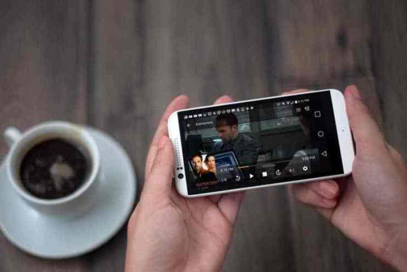


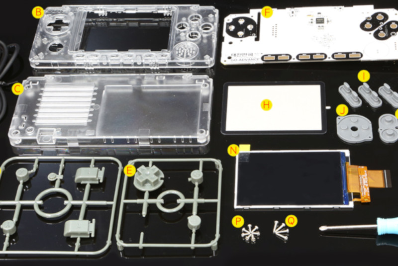


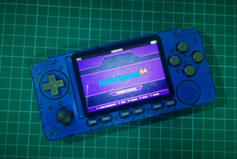
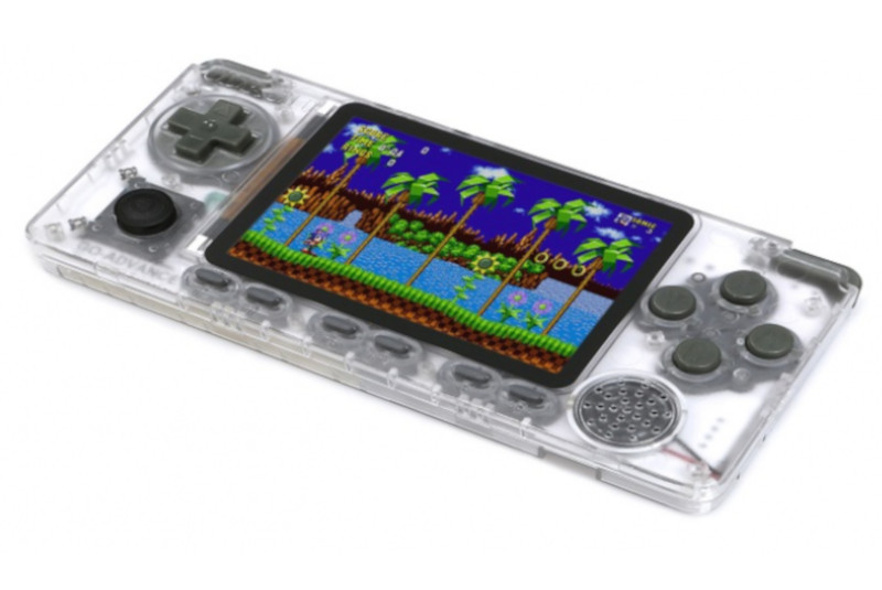

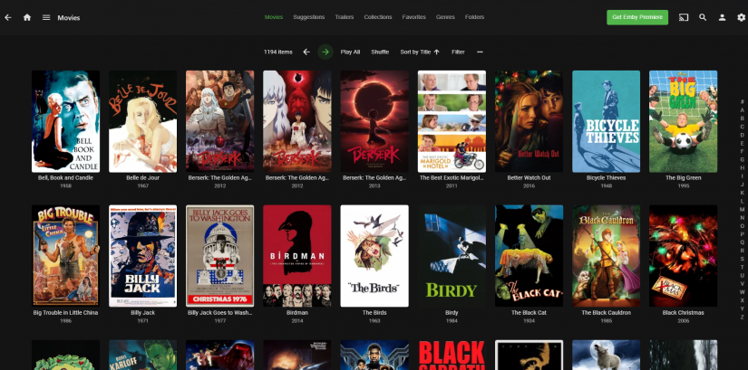
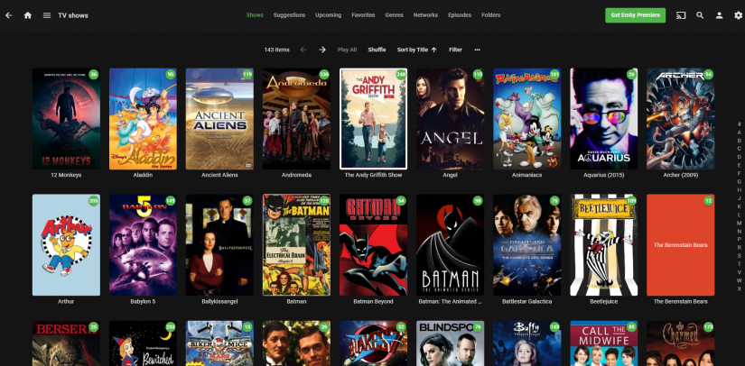

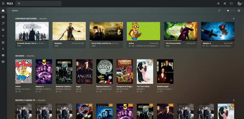

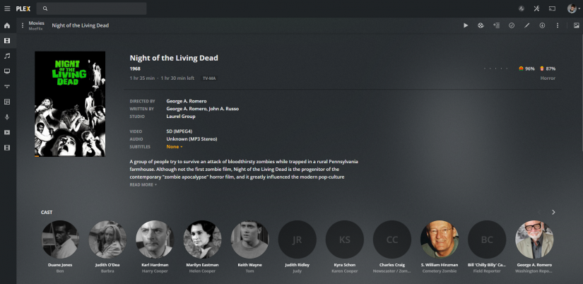
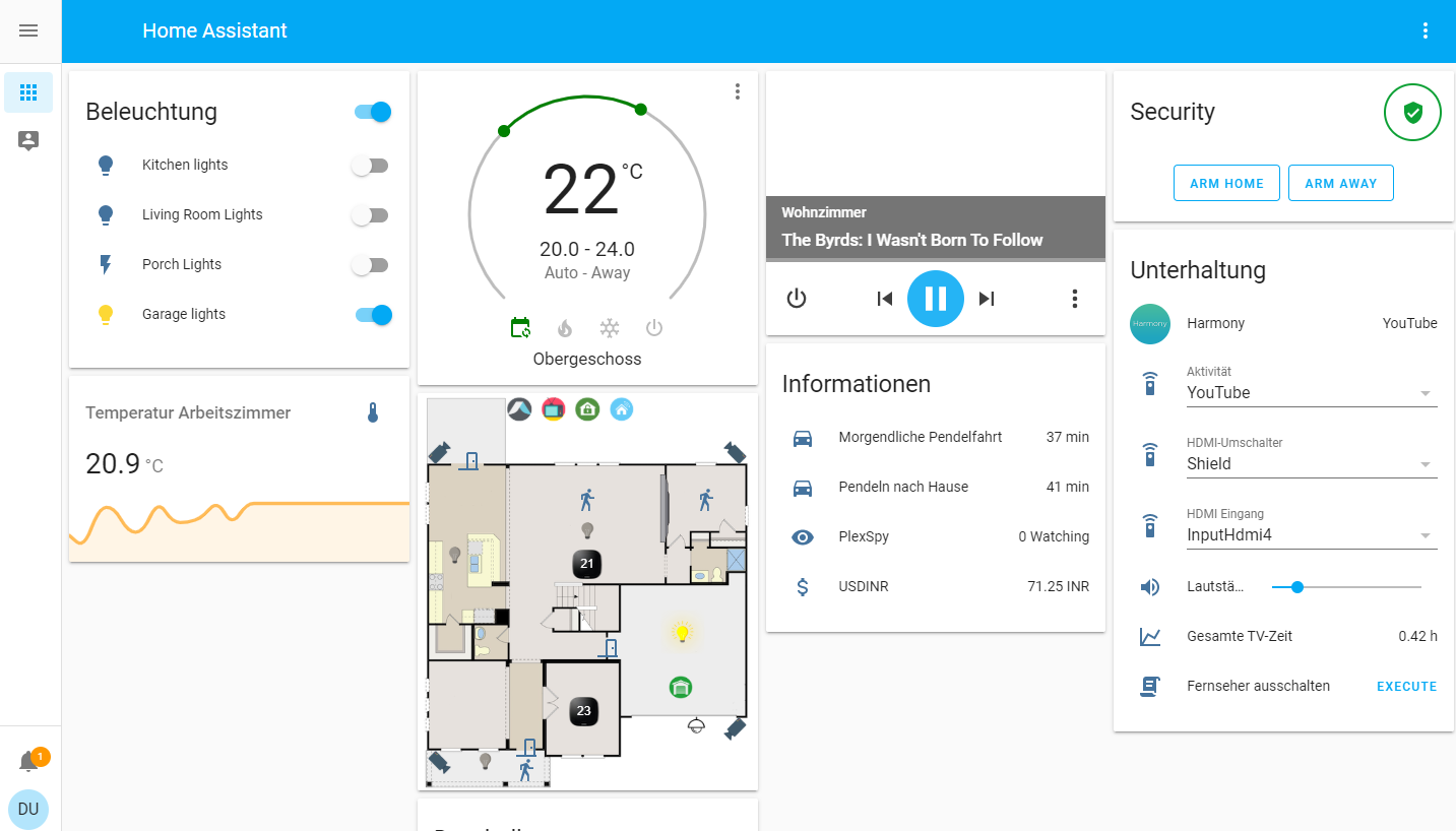
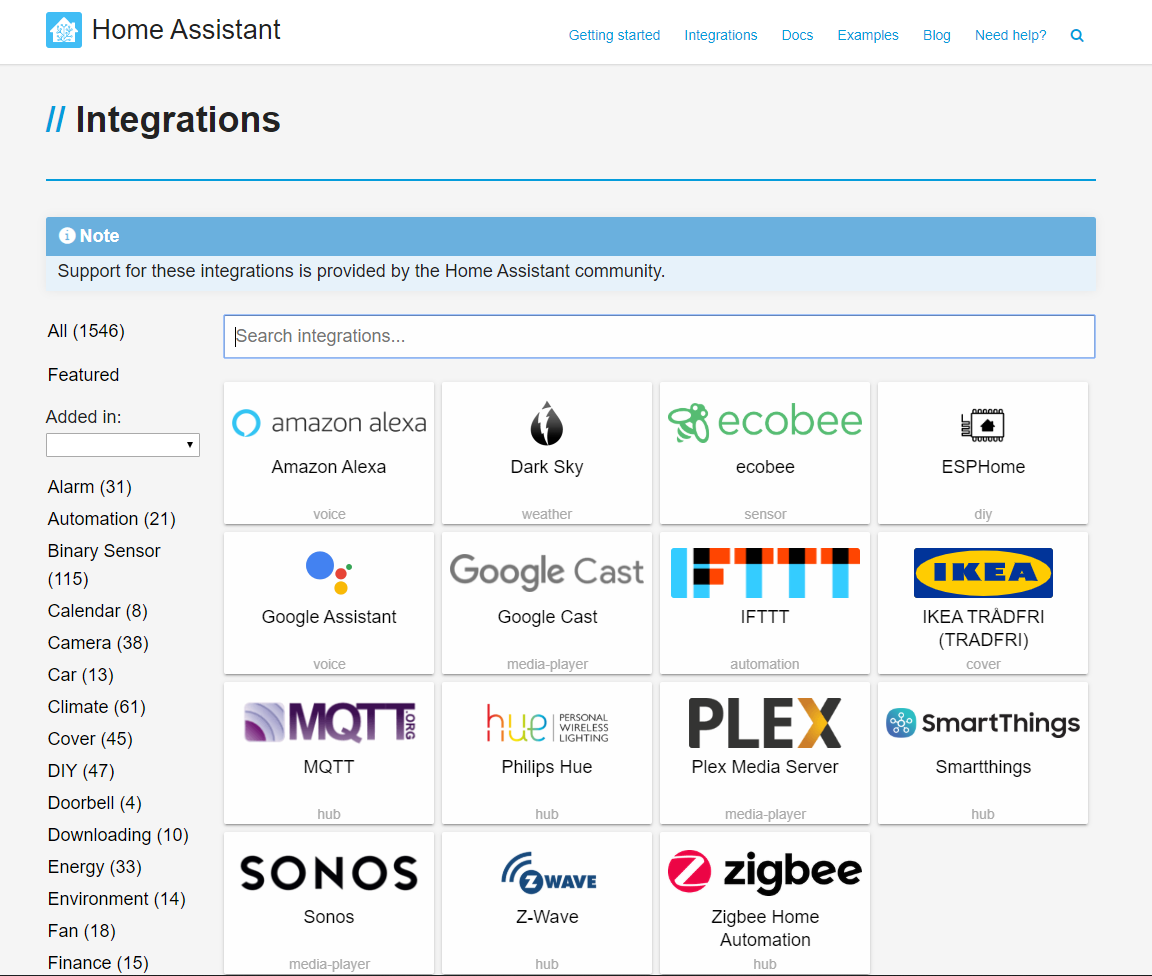
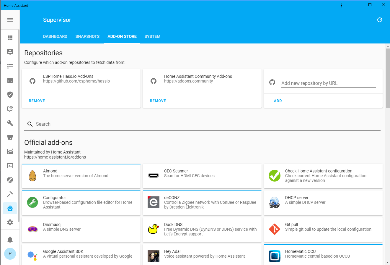
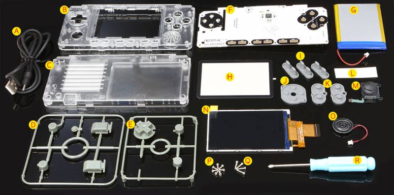
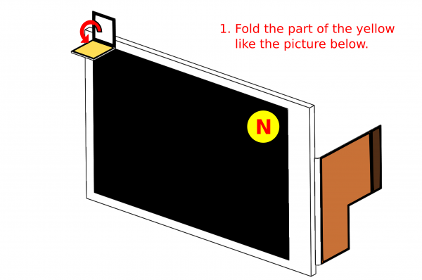 Figure 2 - Fold the yellow tab as shown
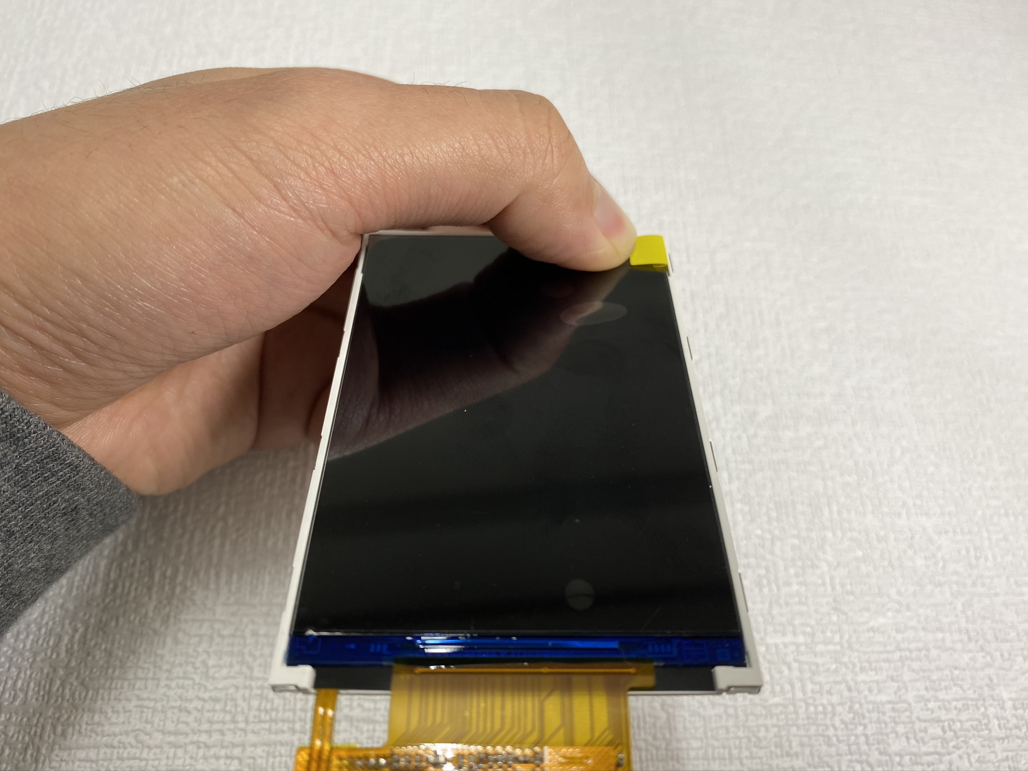
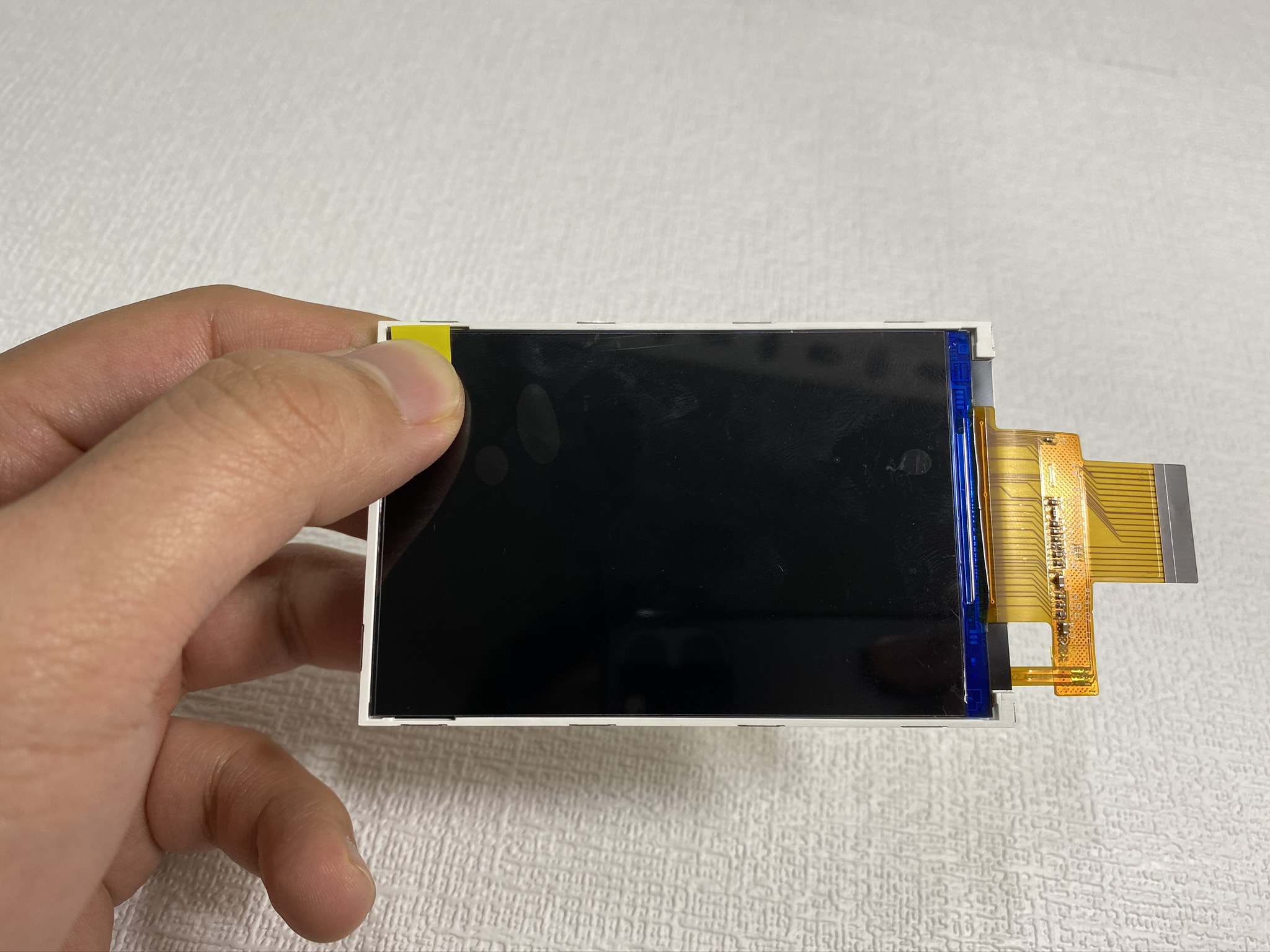
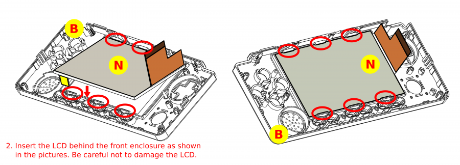
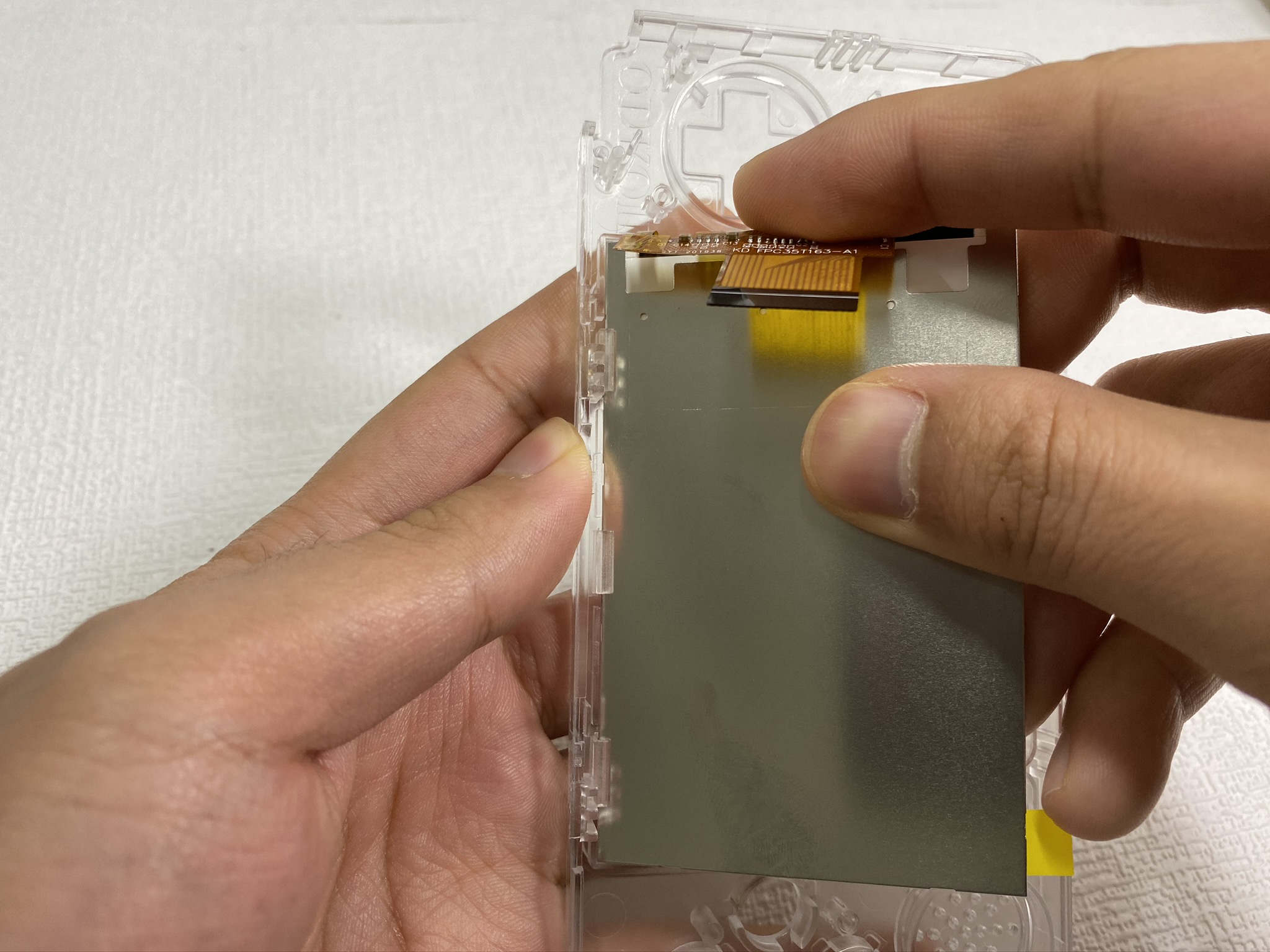
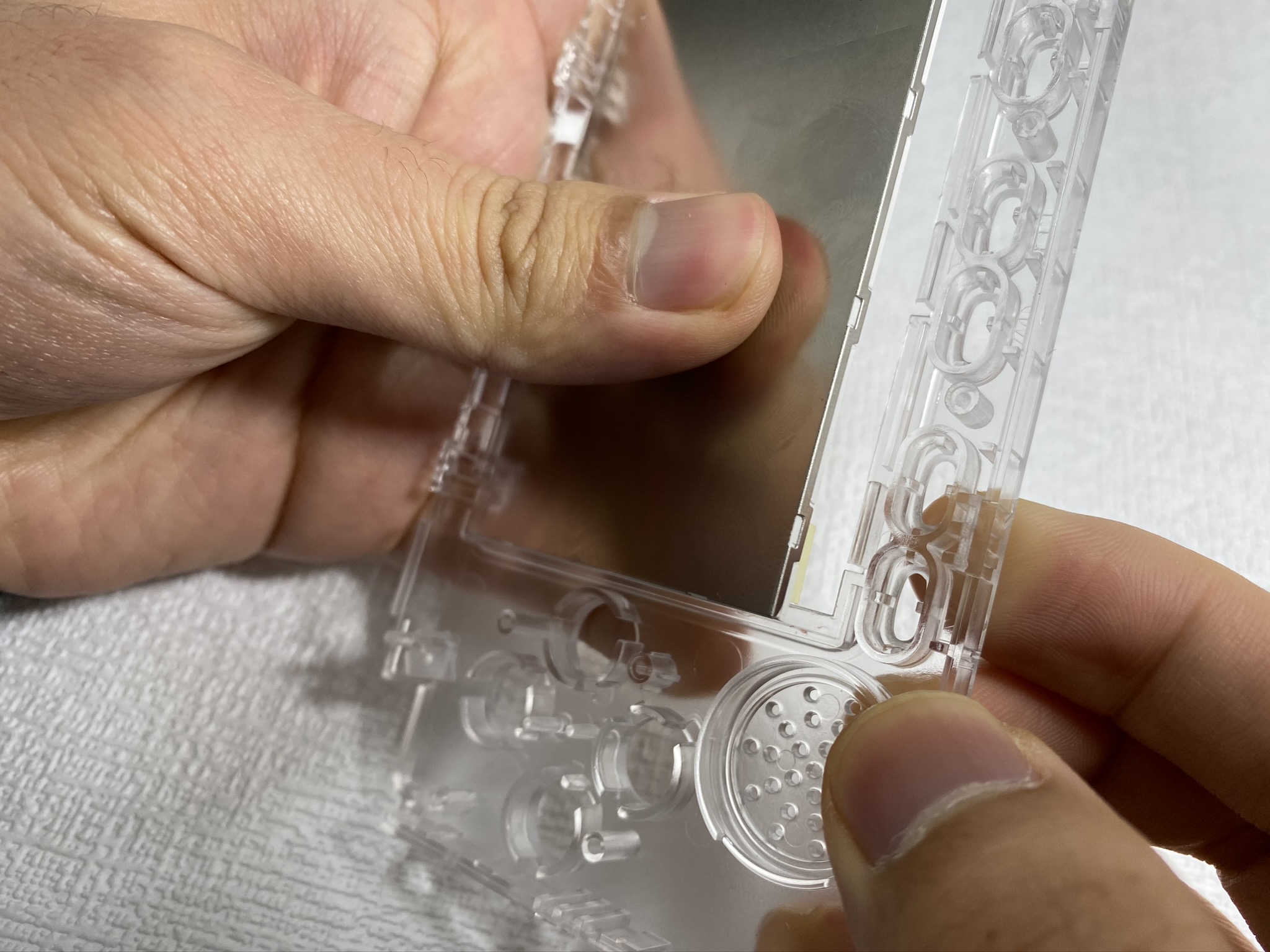
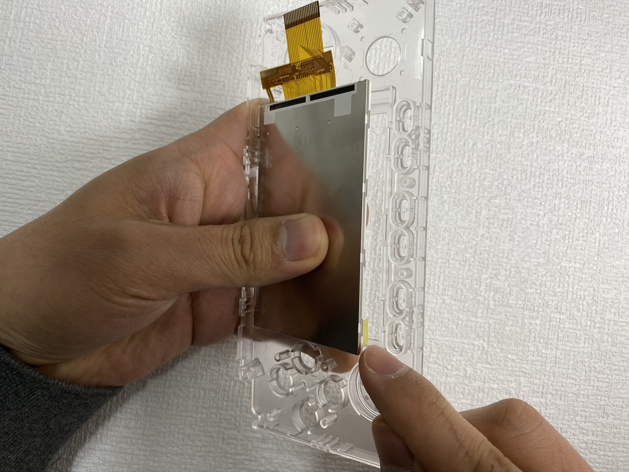
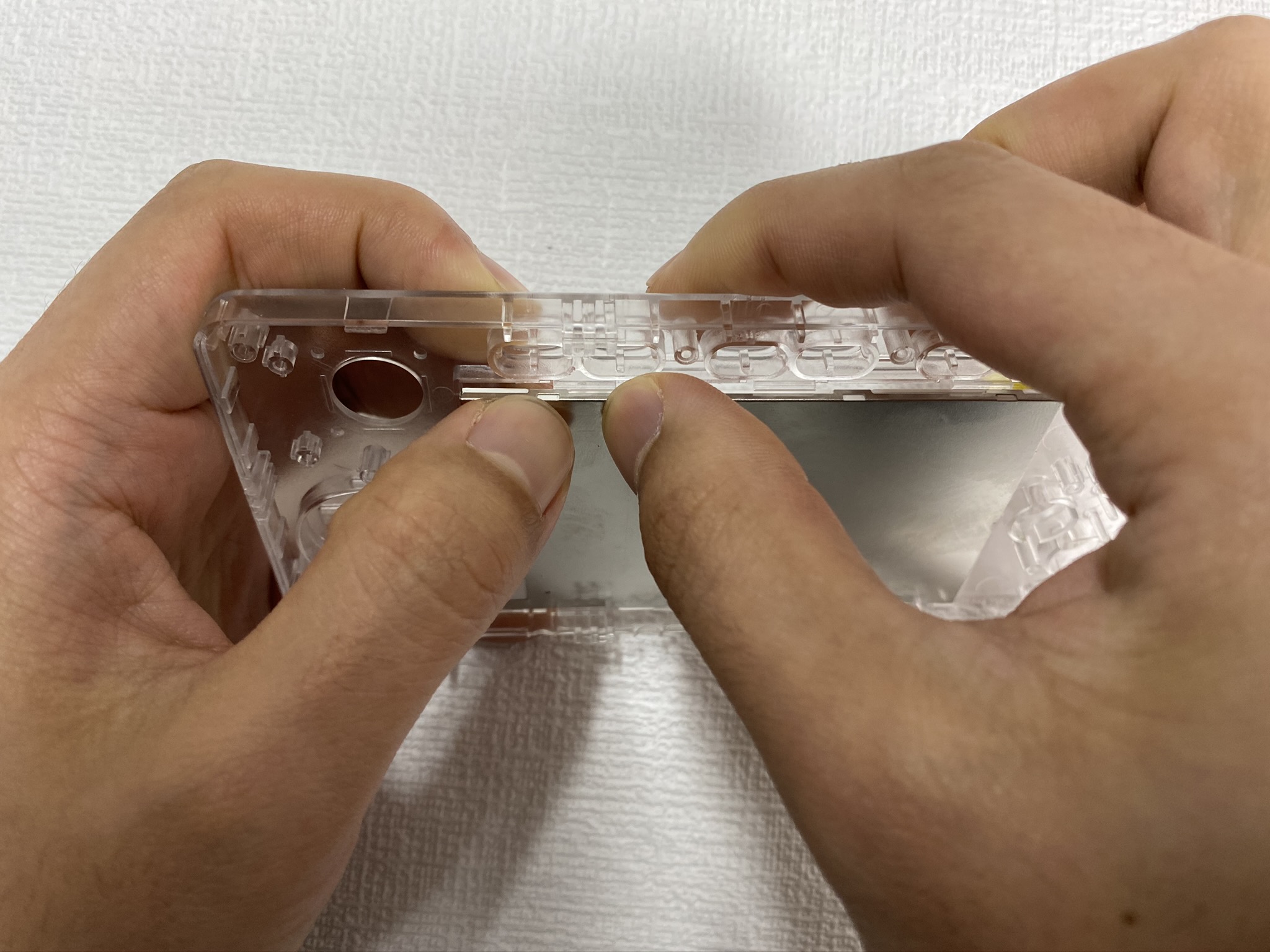
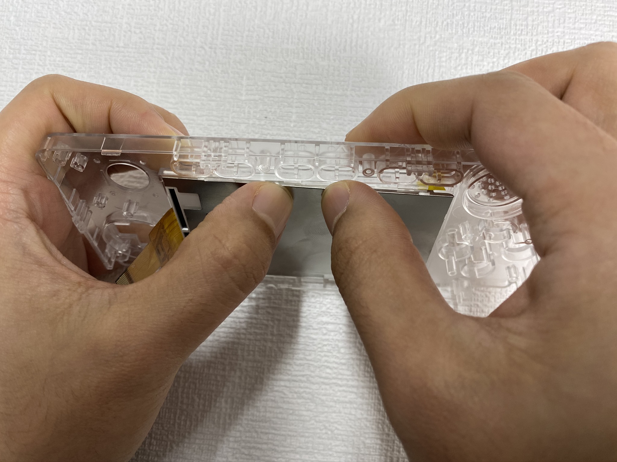
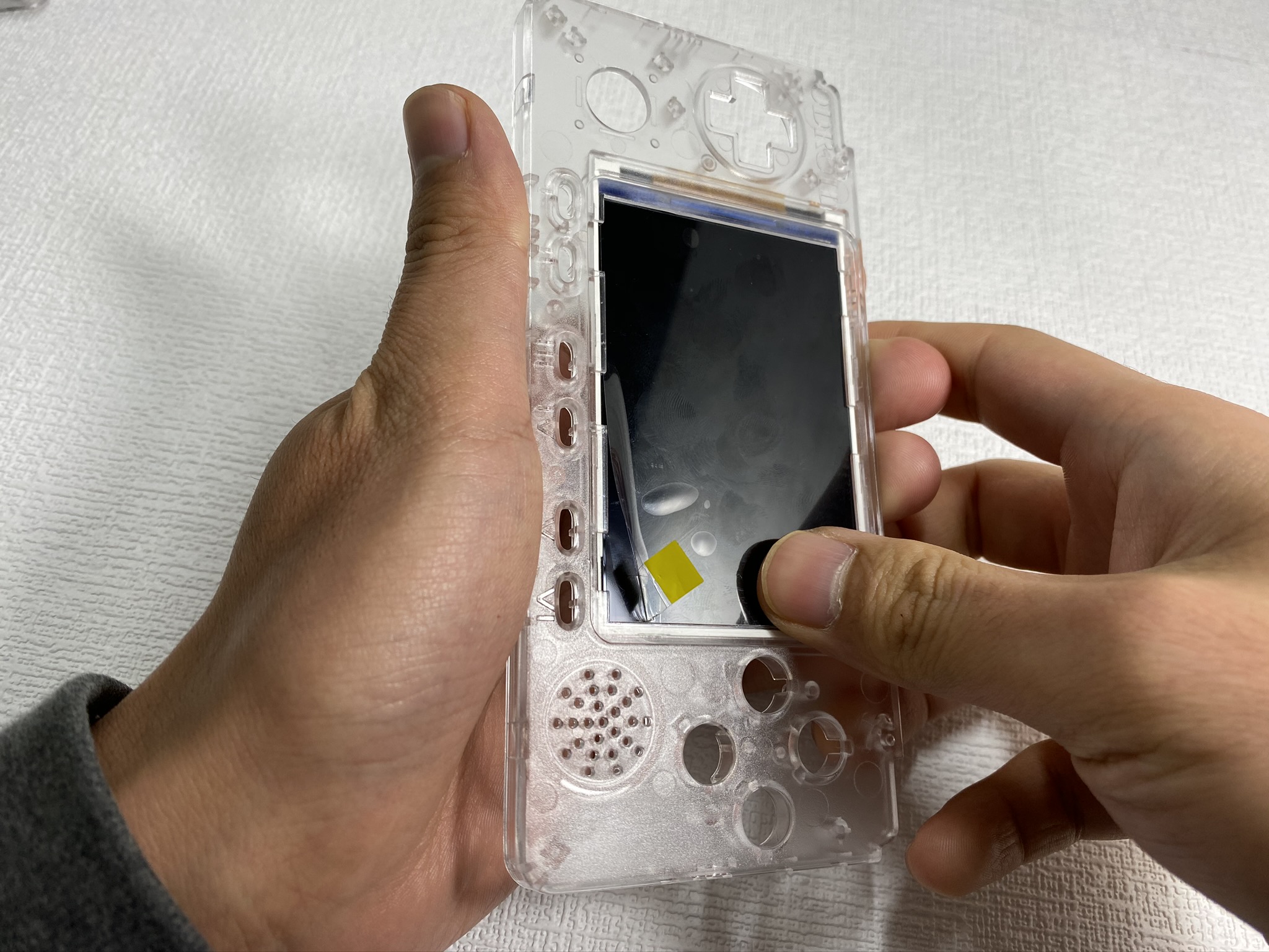

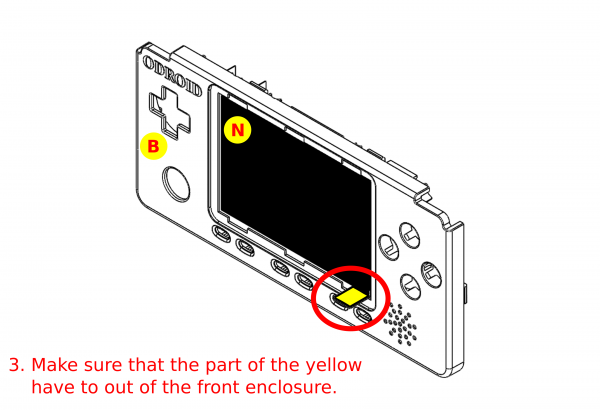
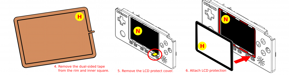
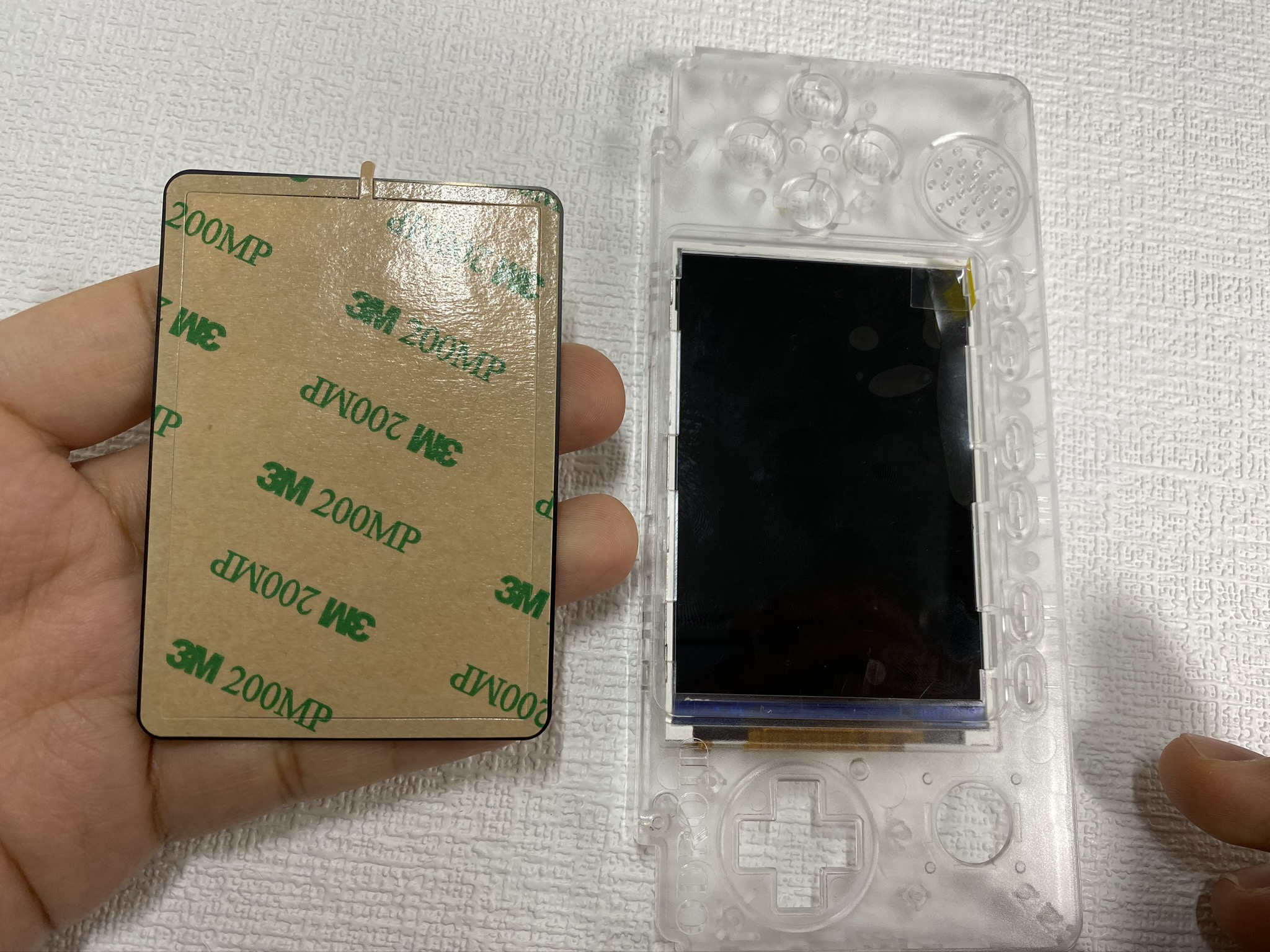

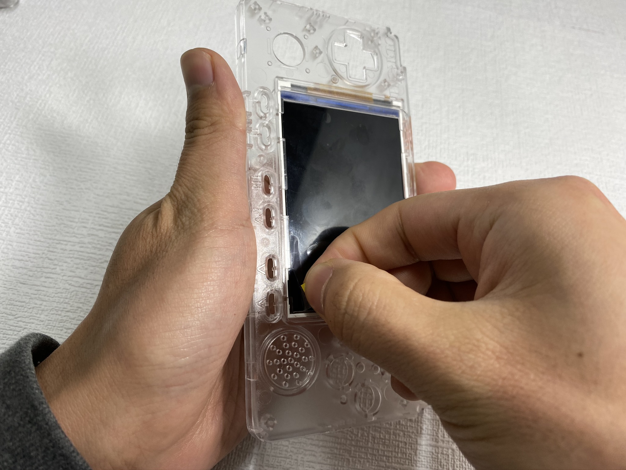
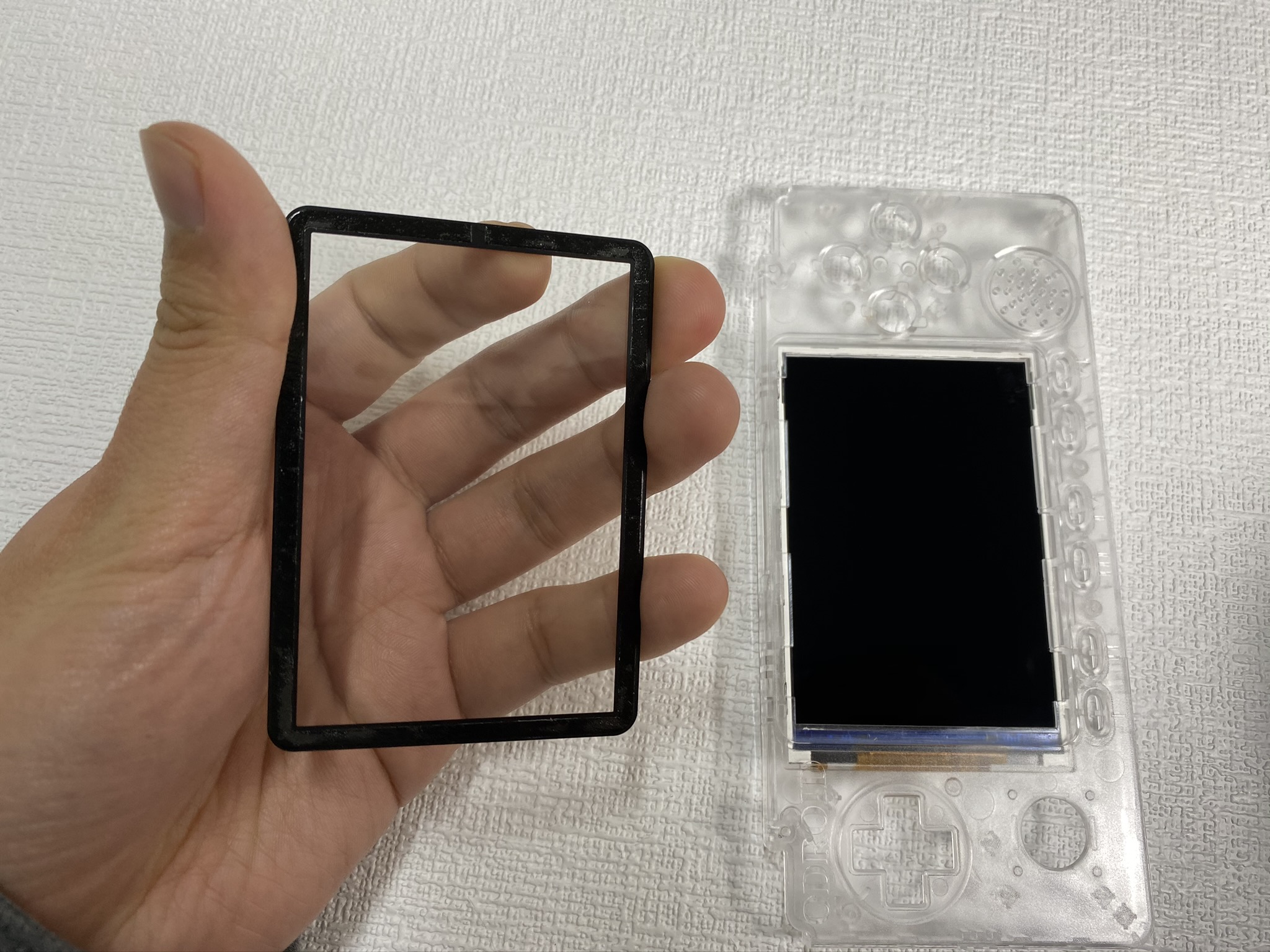
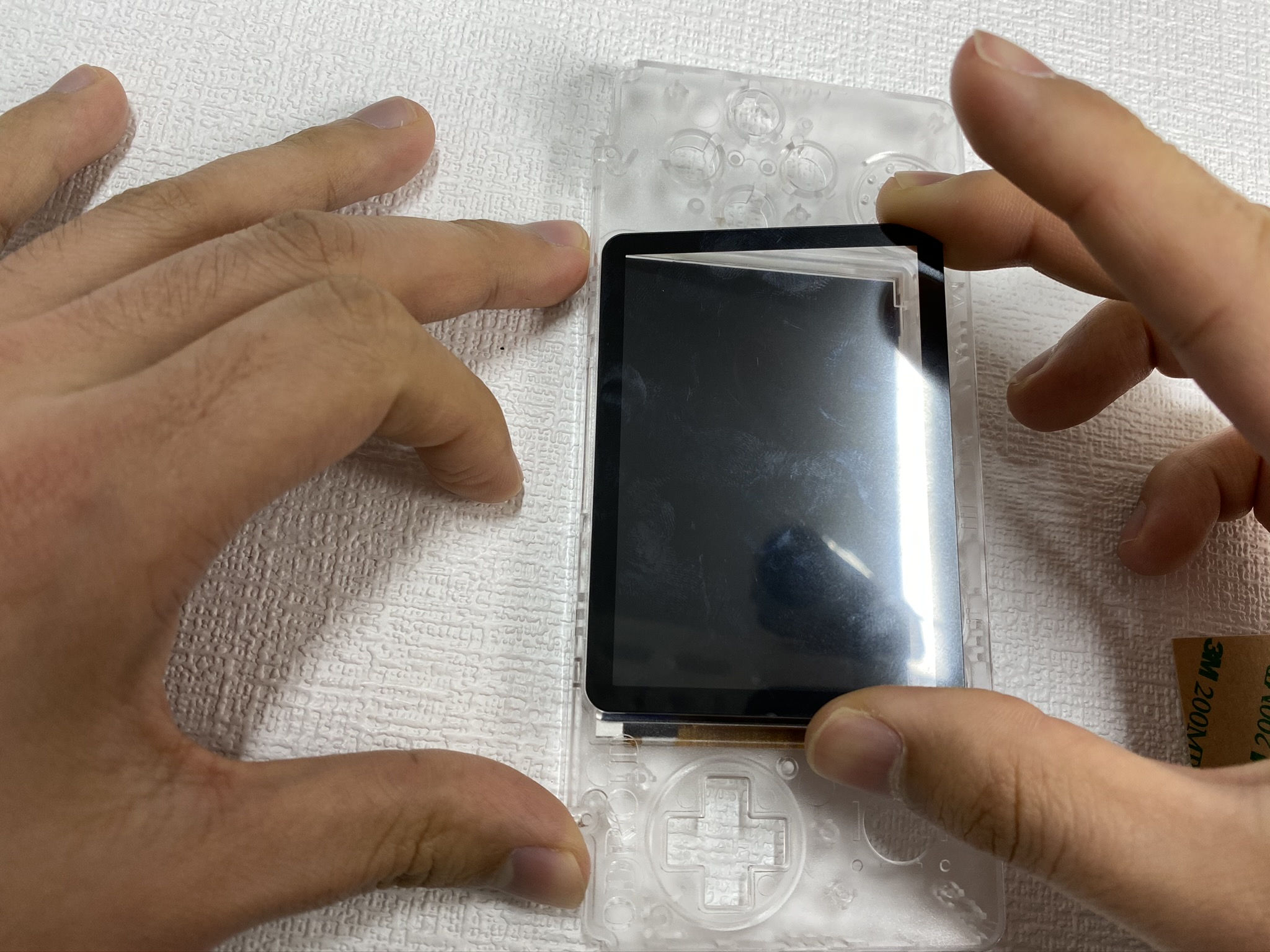
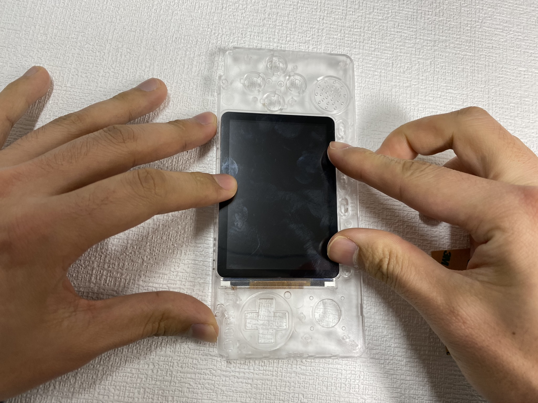
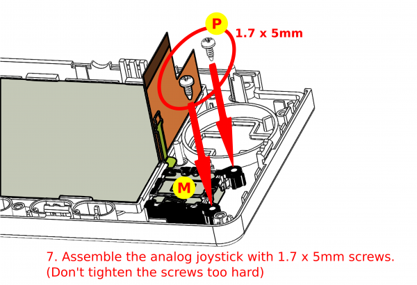
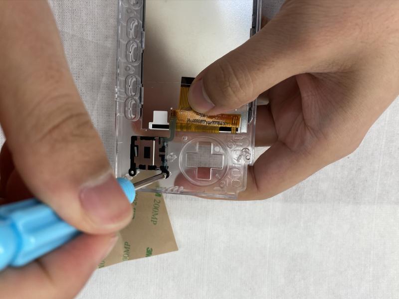
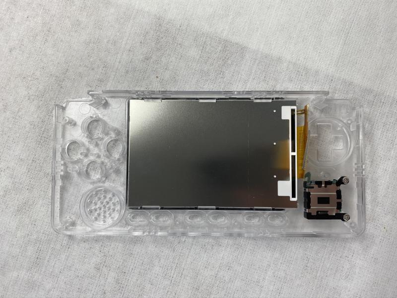
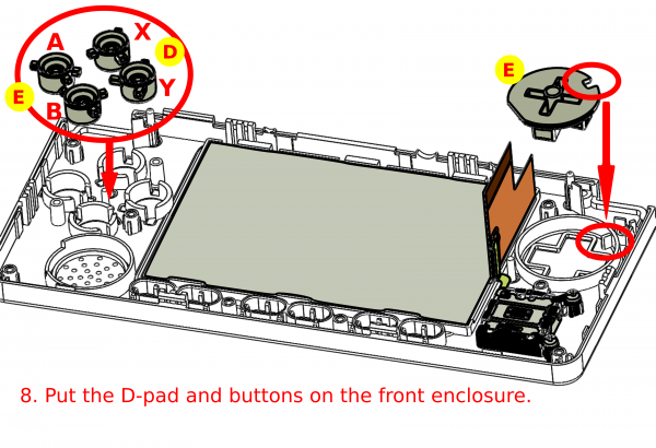 Figure 24 - Put the D-pad and buttons on the front enclosure
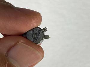
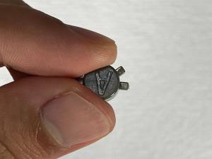
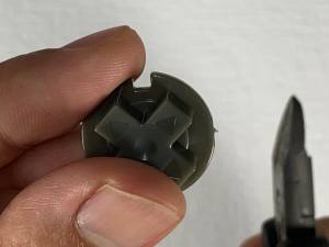 Figure 27 - Closeup of attaching the buttons
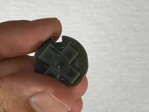
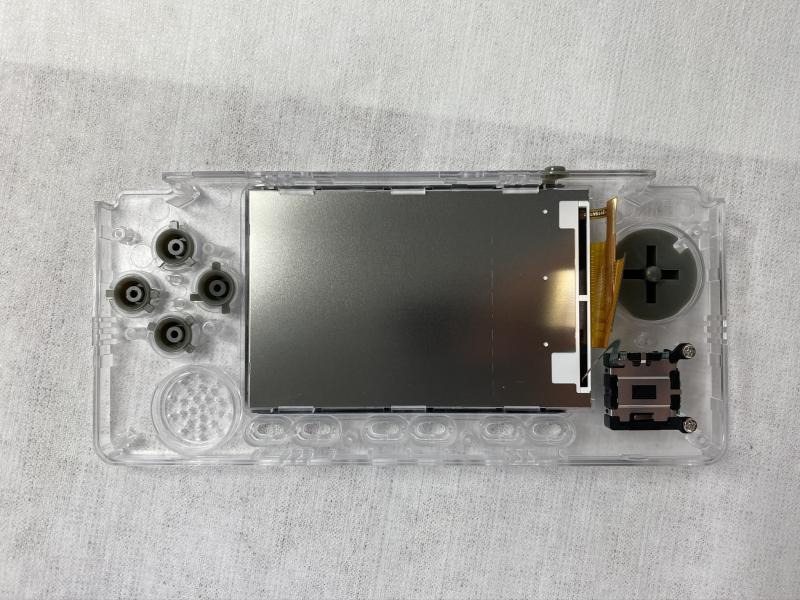
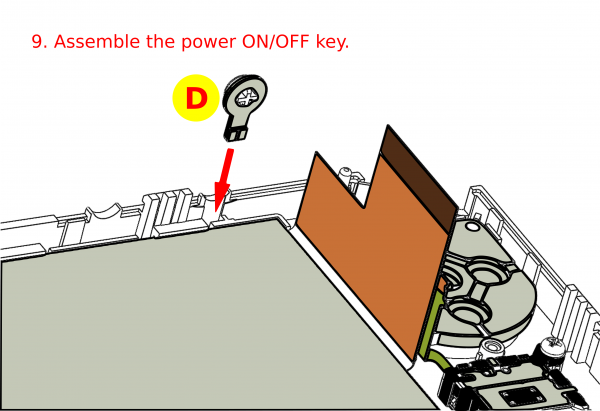
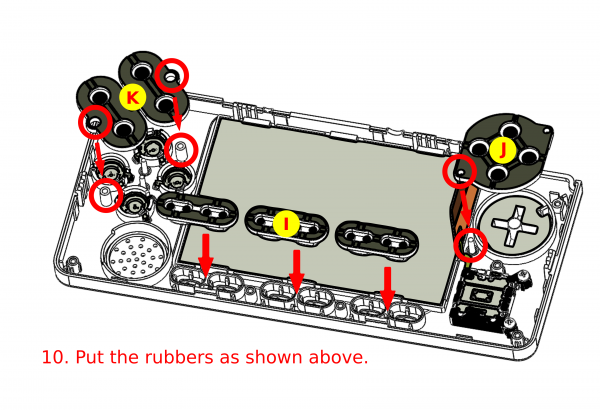
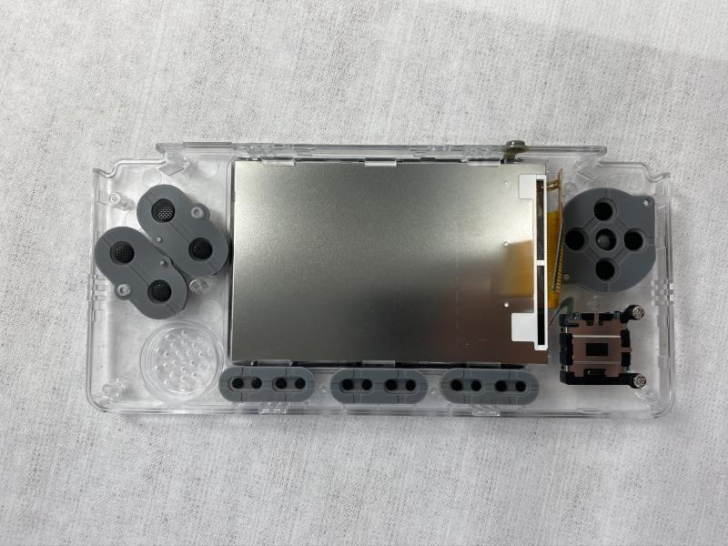
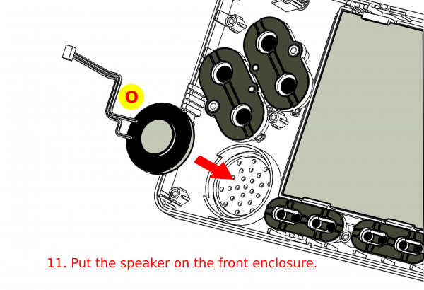
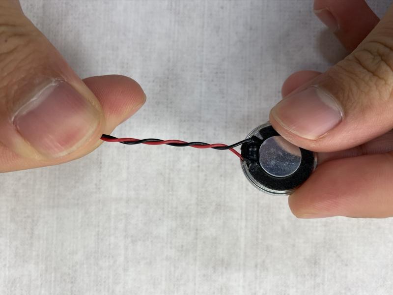
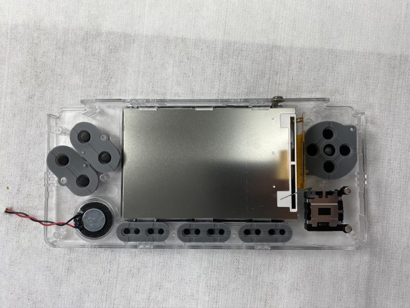
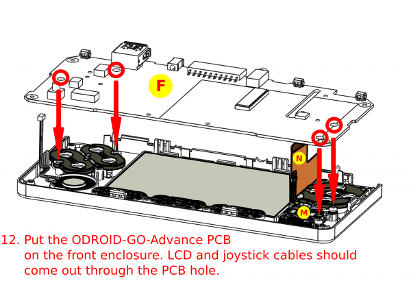
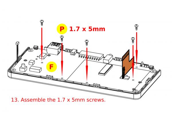
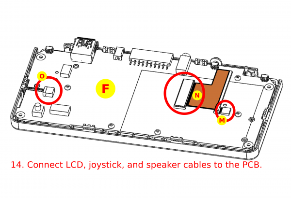
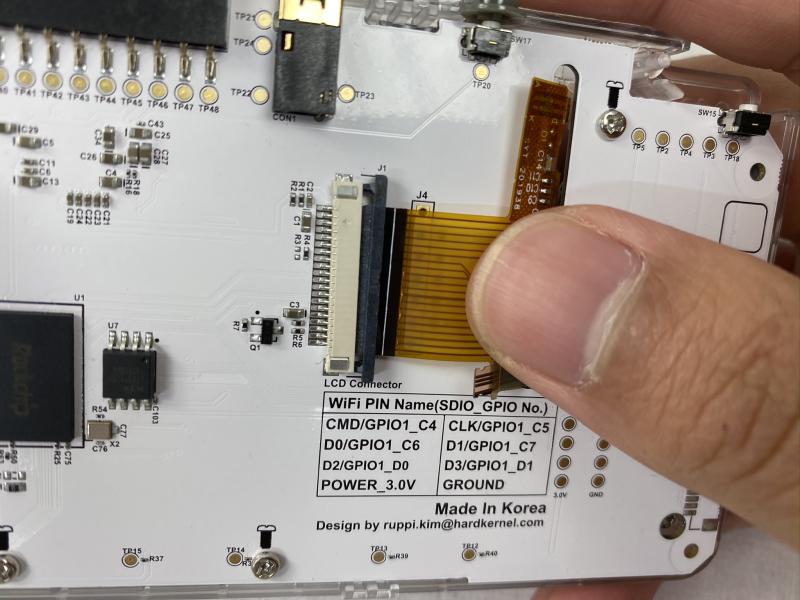
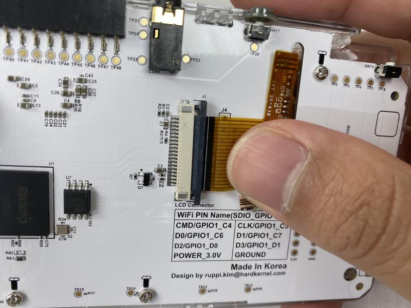
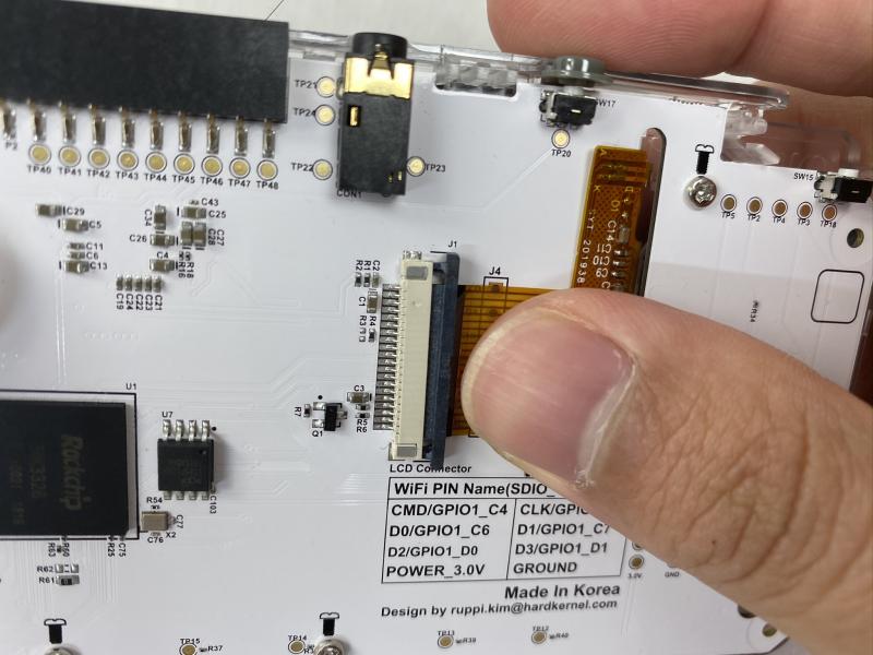
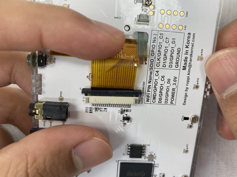
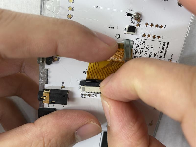
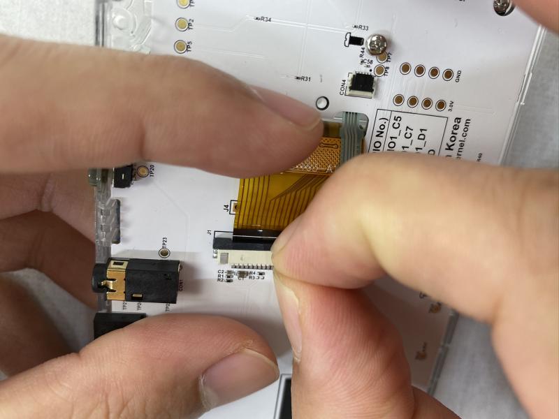
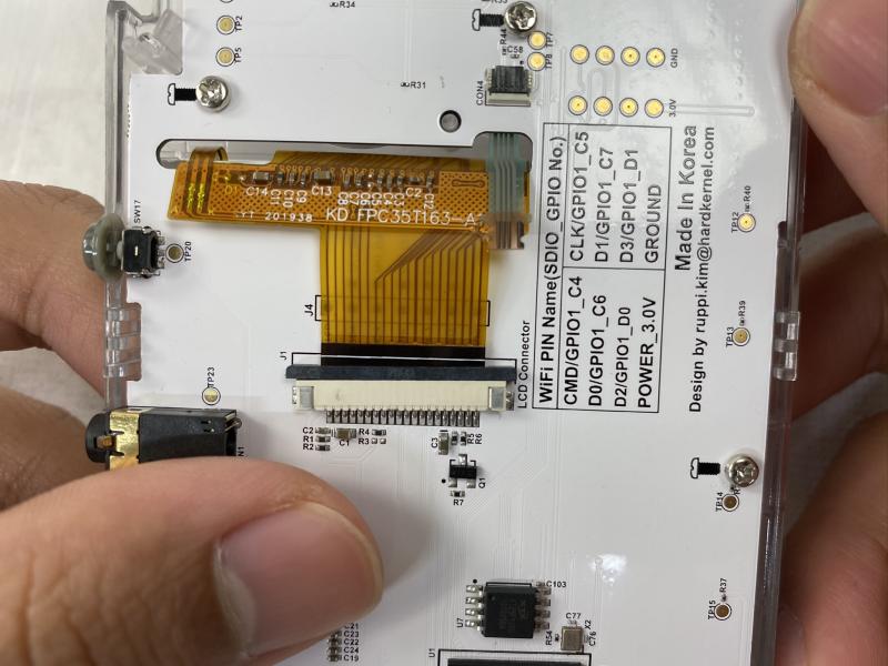
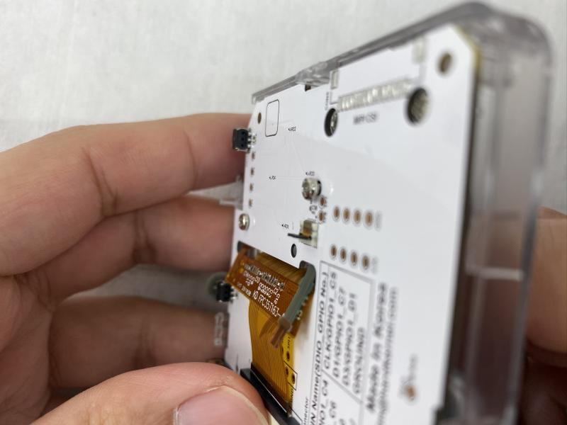
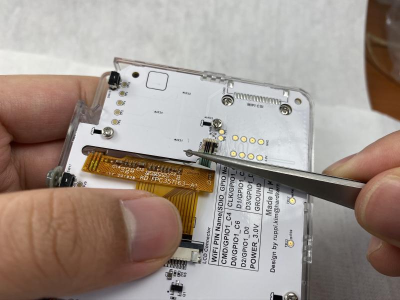
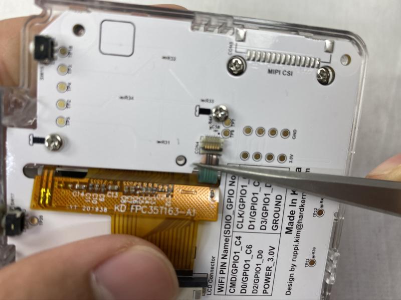
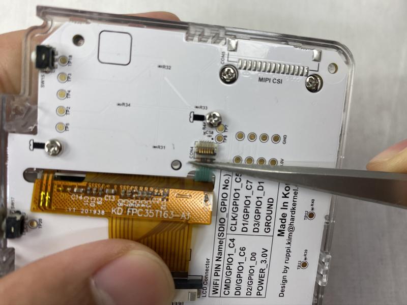
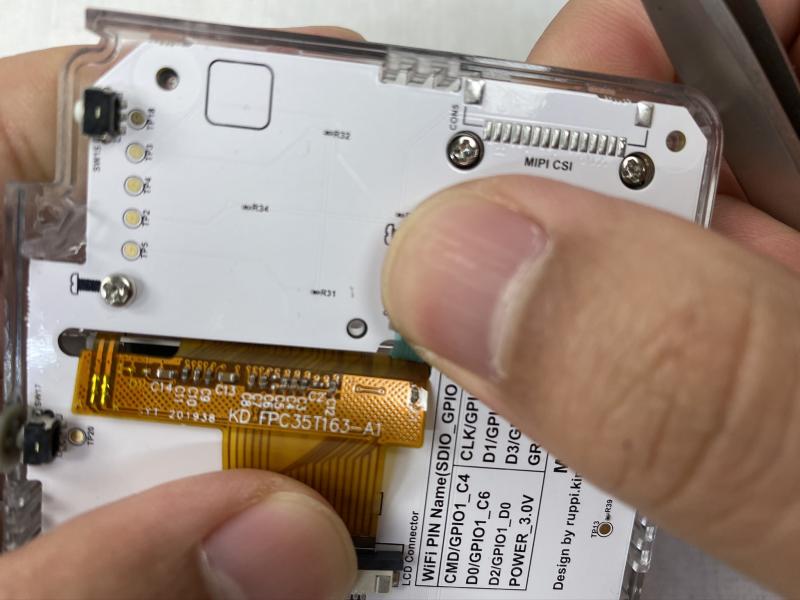
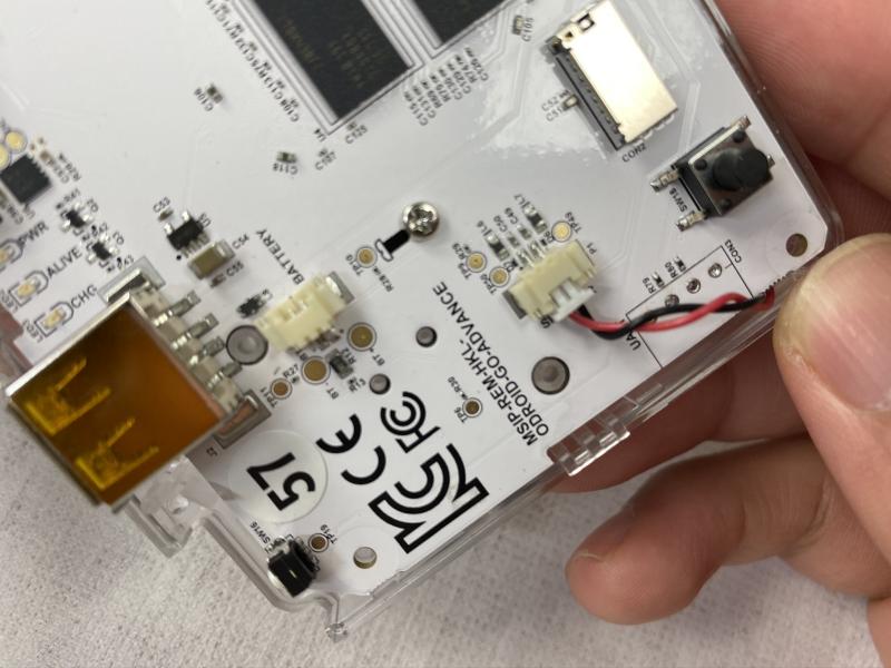
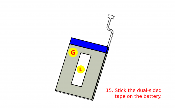
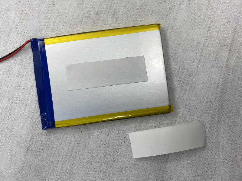
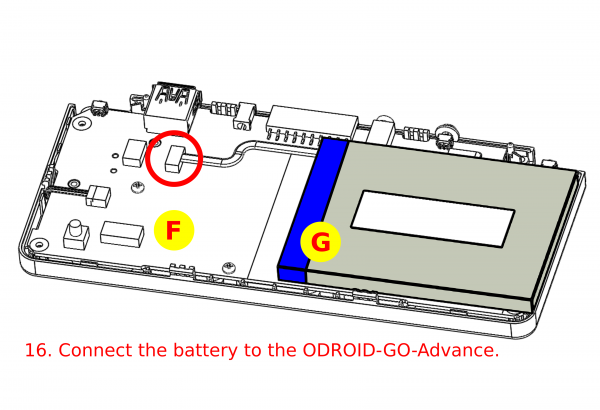
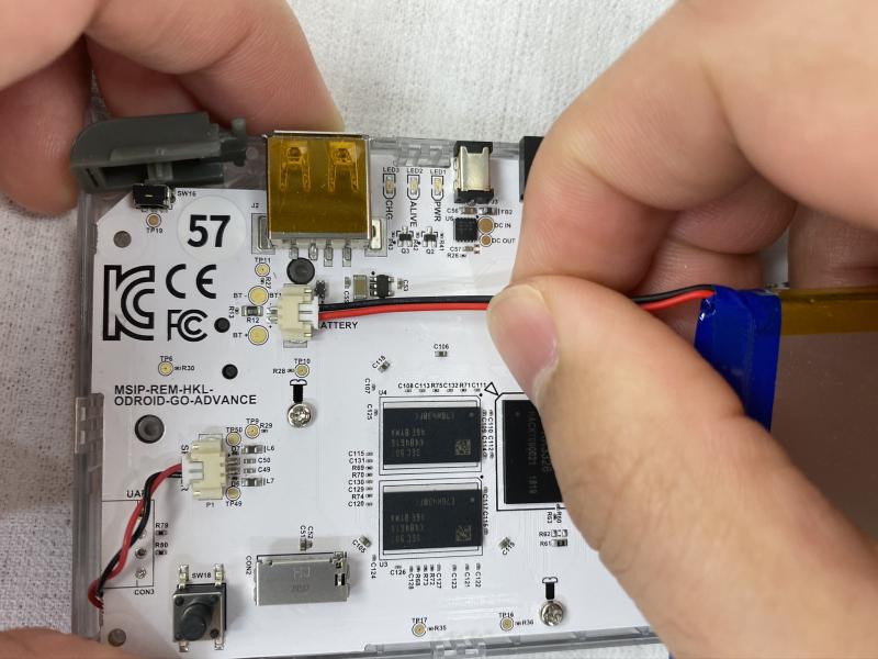
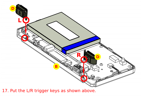
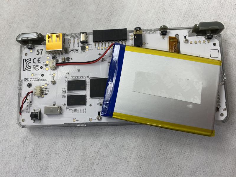
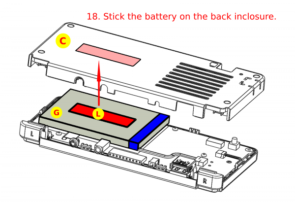
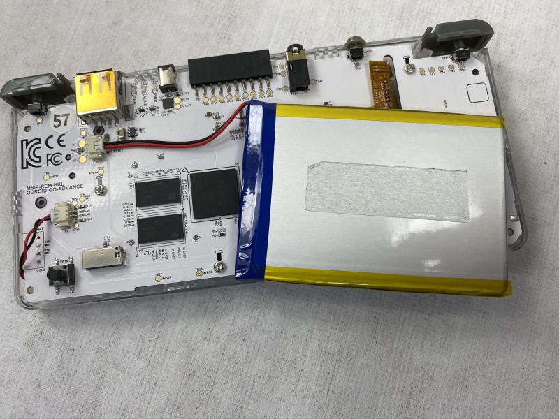
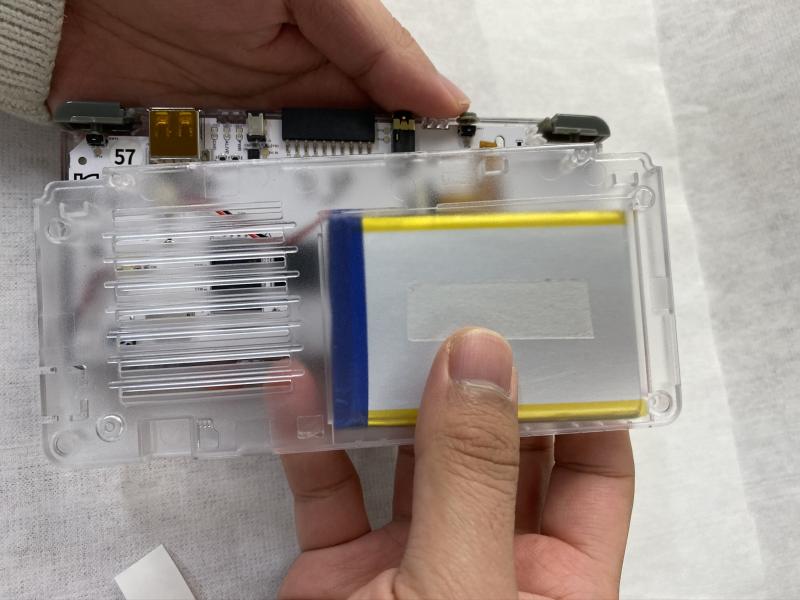
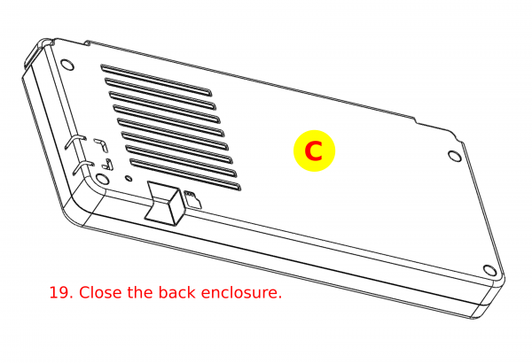
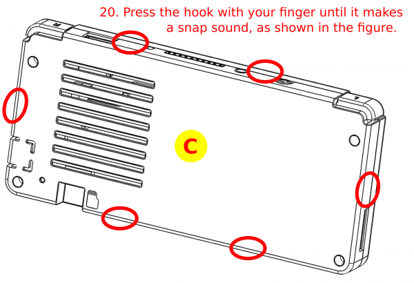
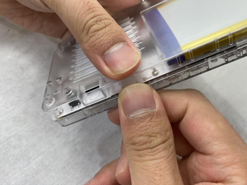
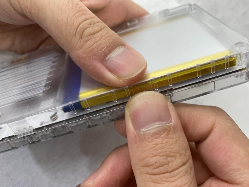
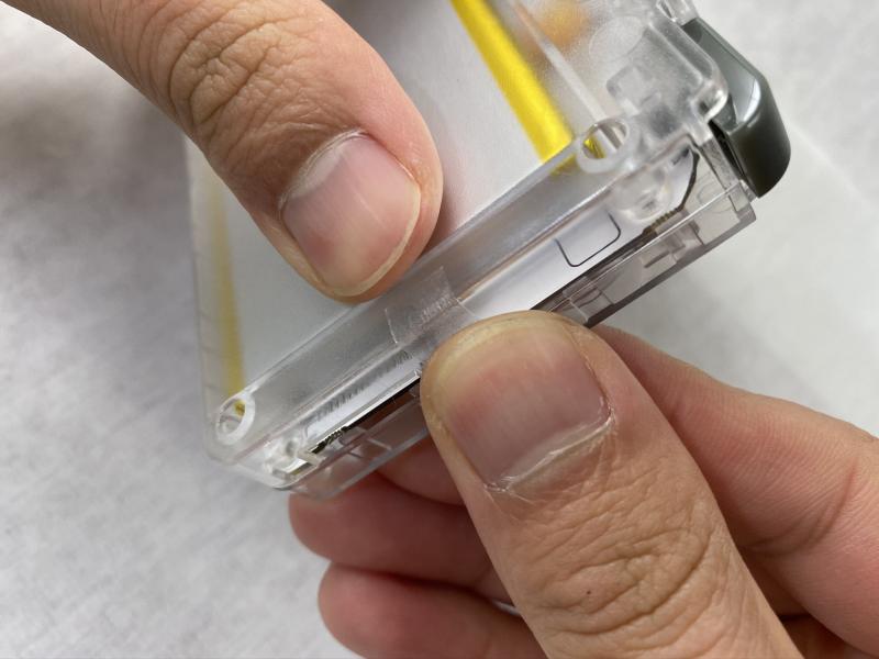
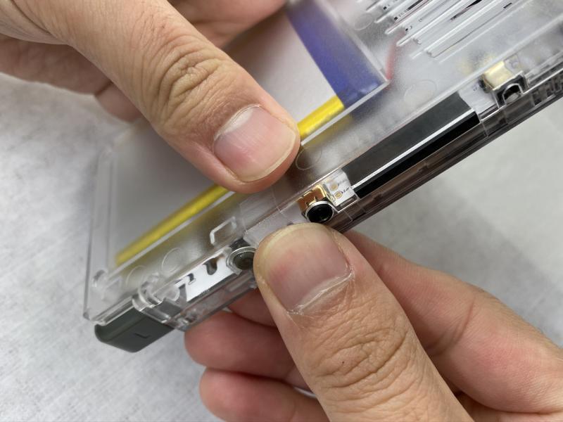
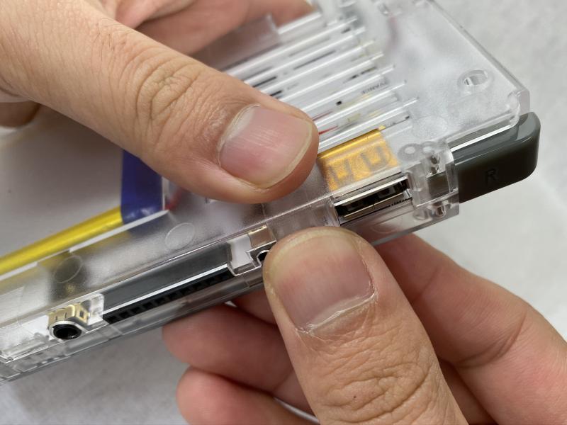
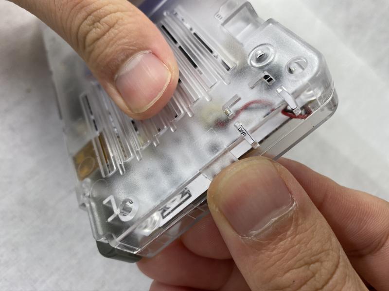
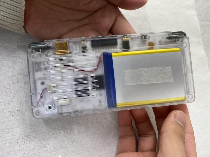
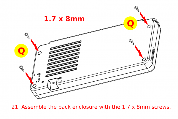
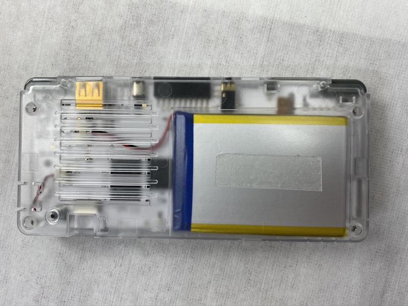
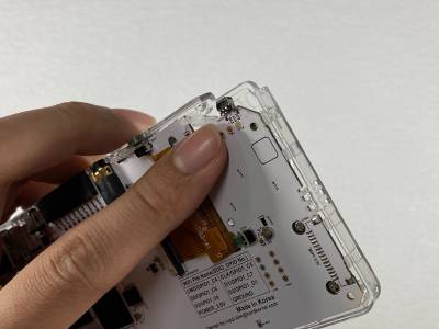
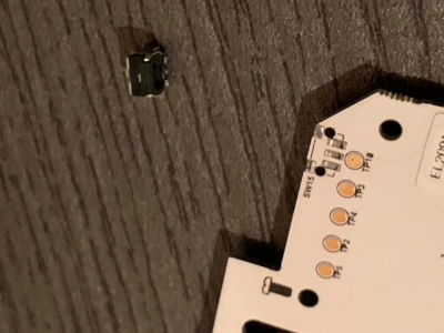
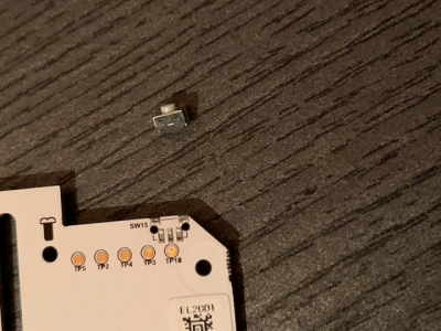
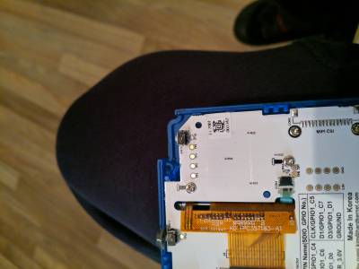
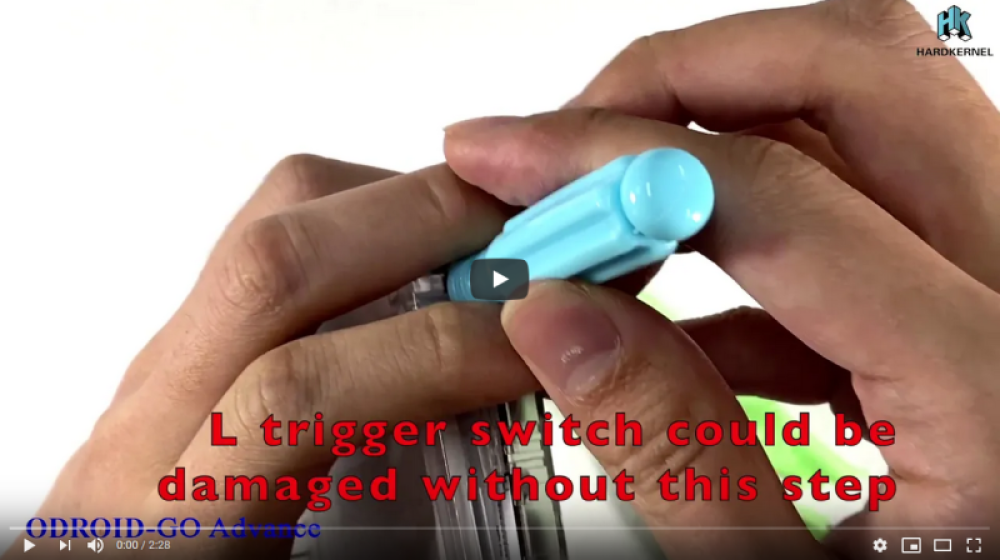
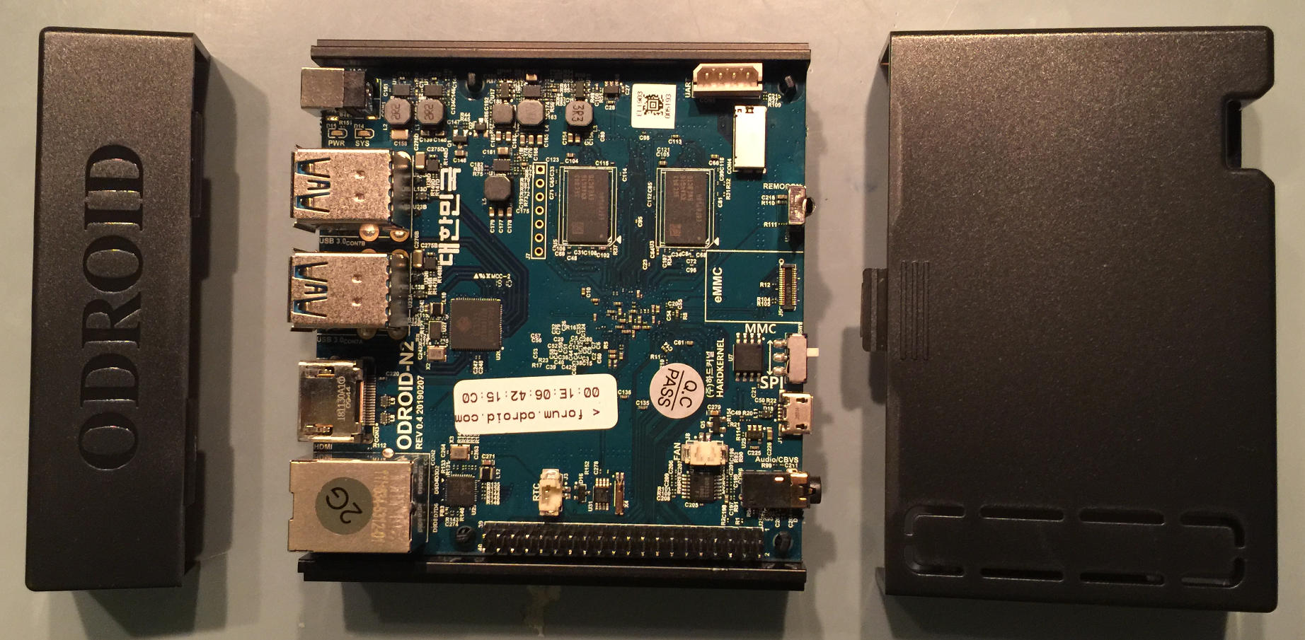
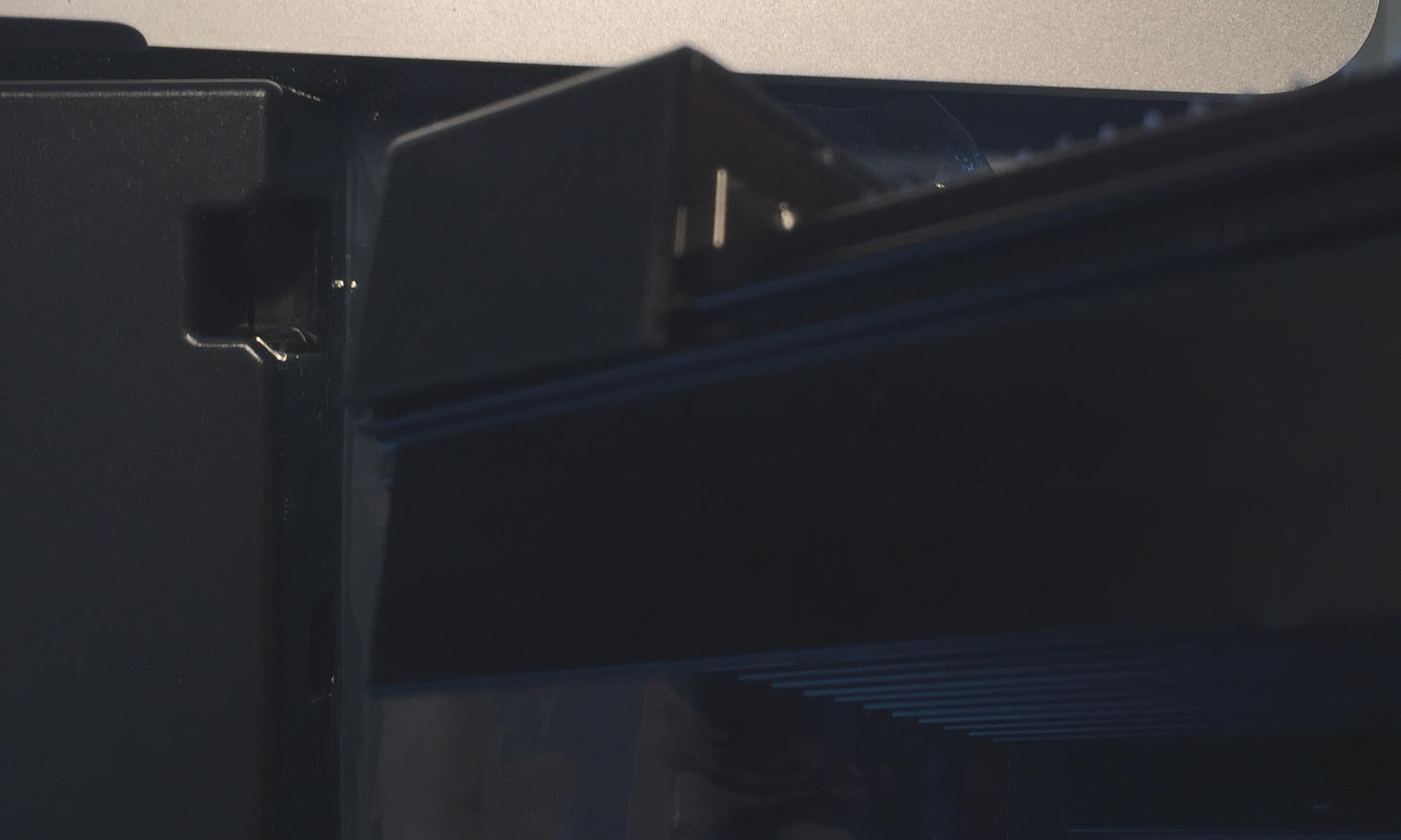
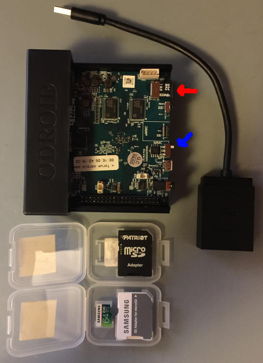
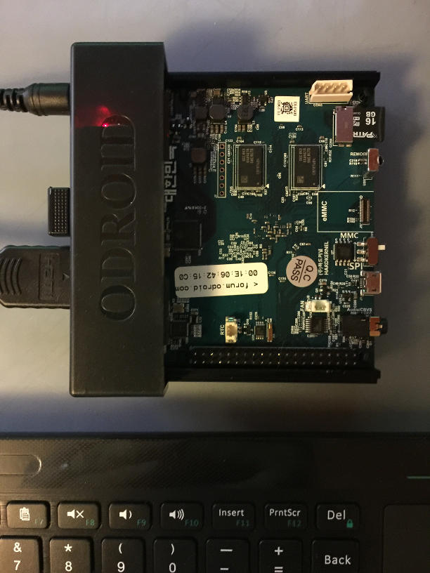
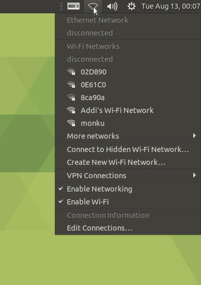
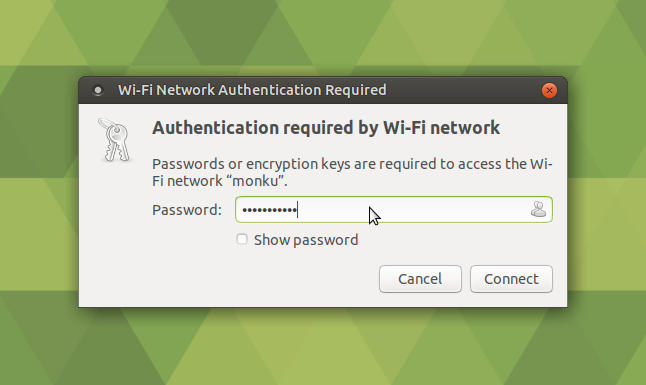
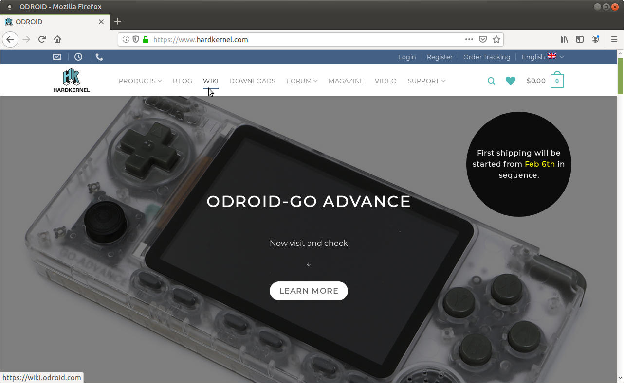
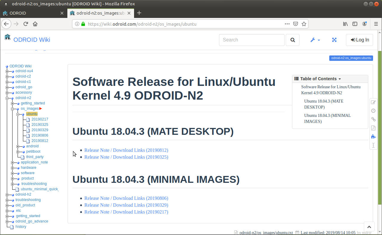
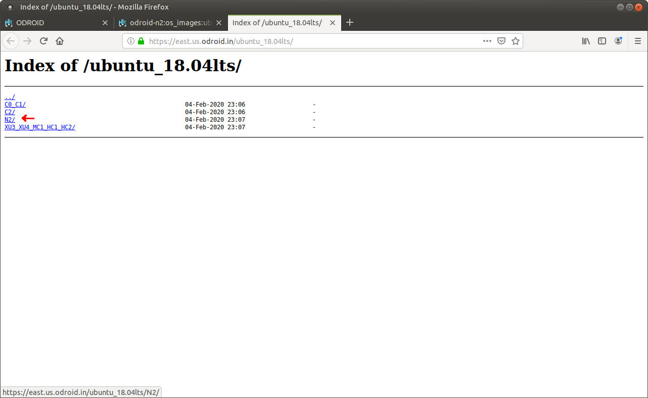
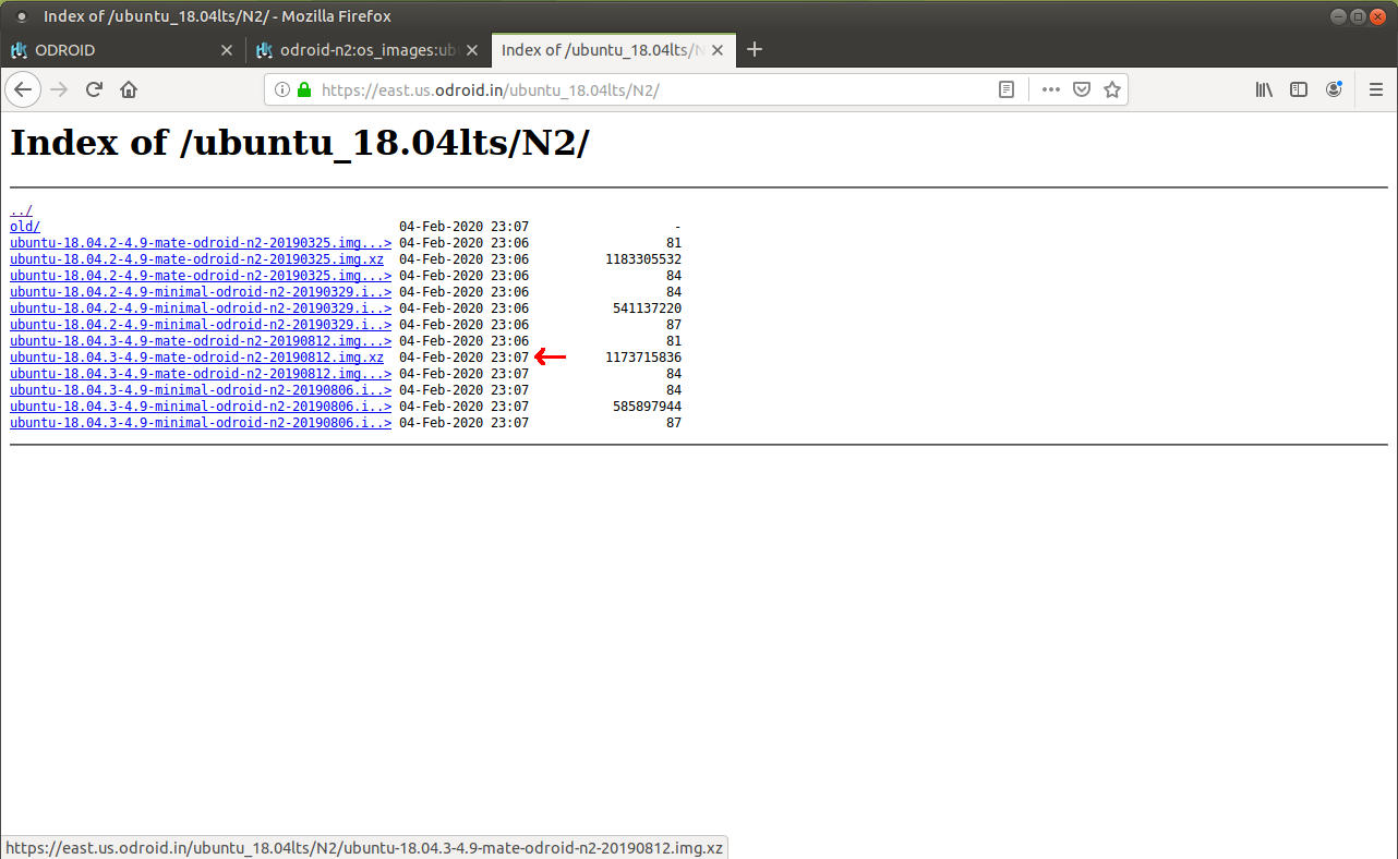
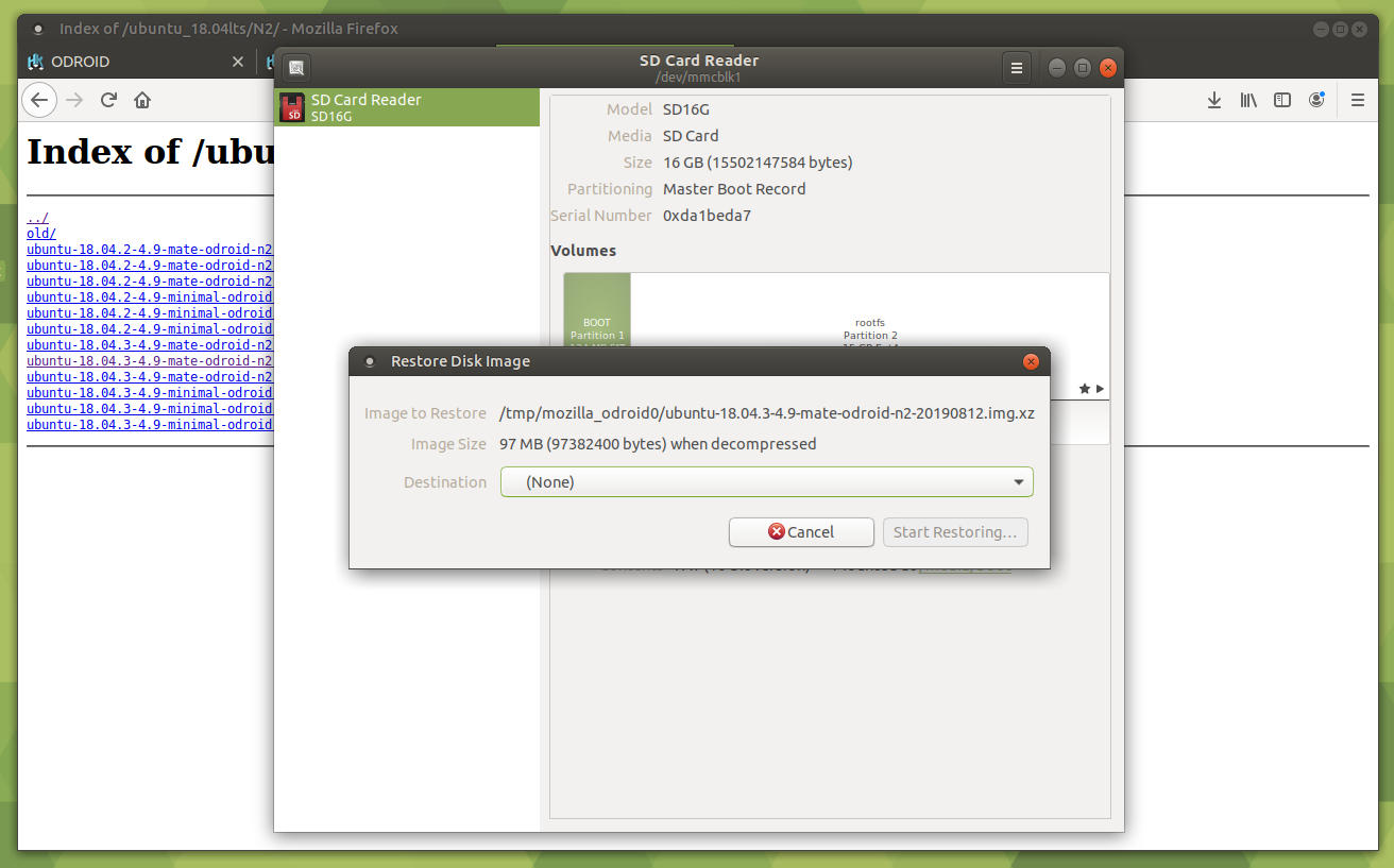
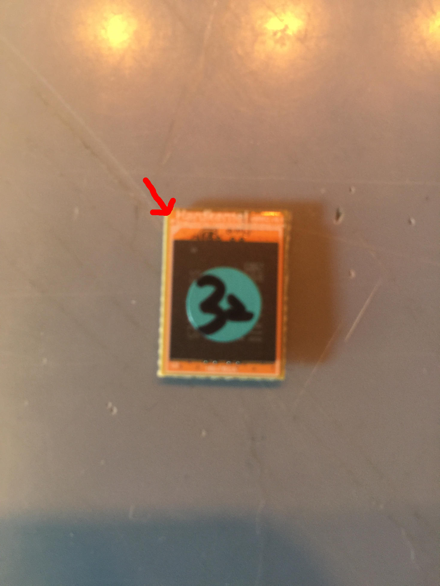
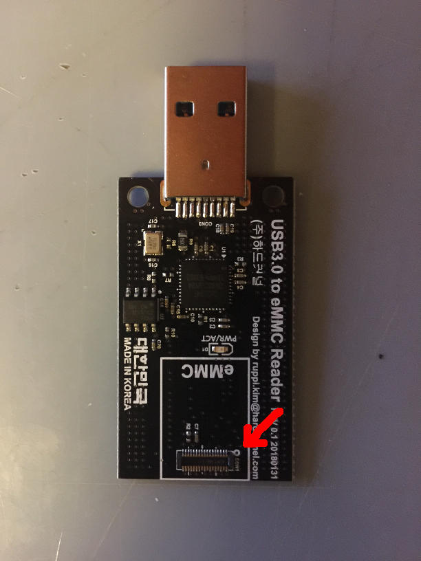
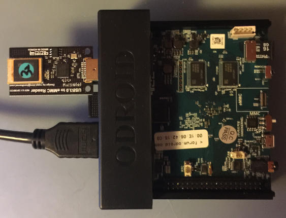
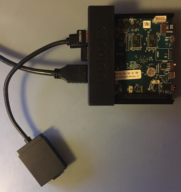
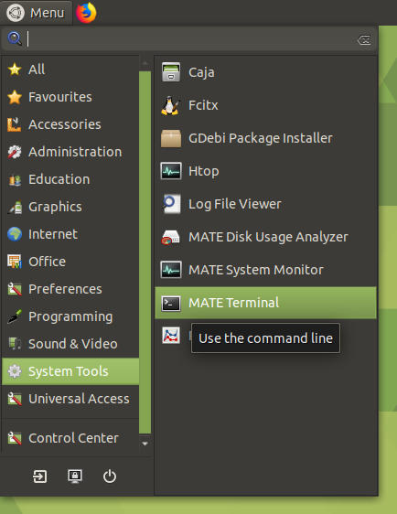
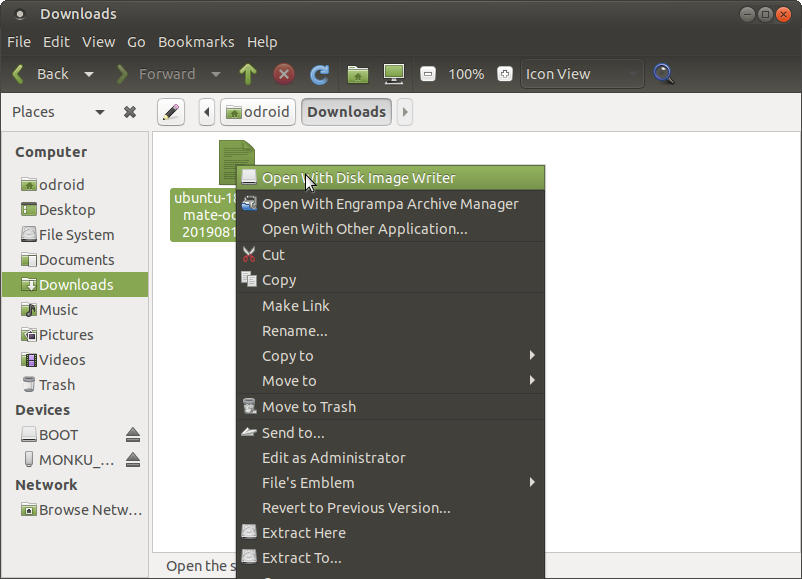
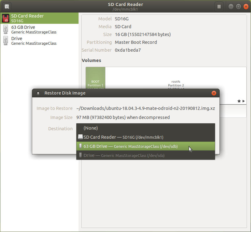
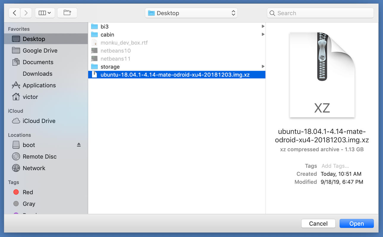
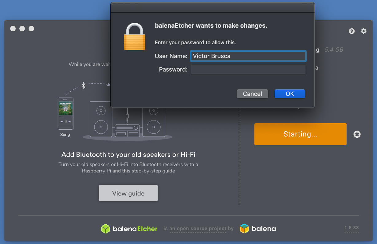
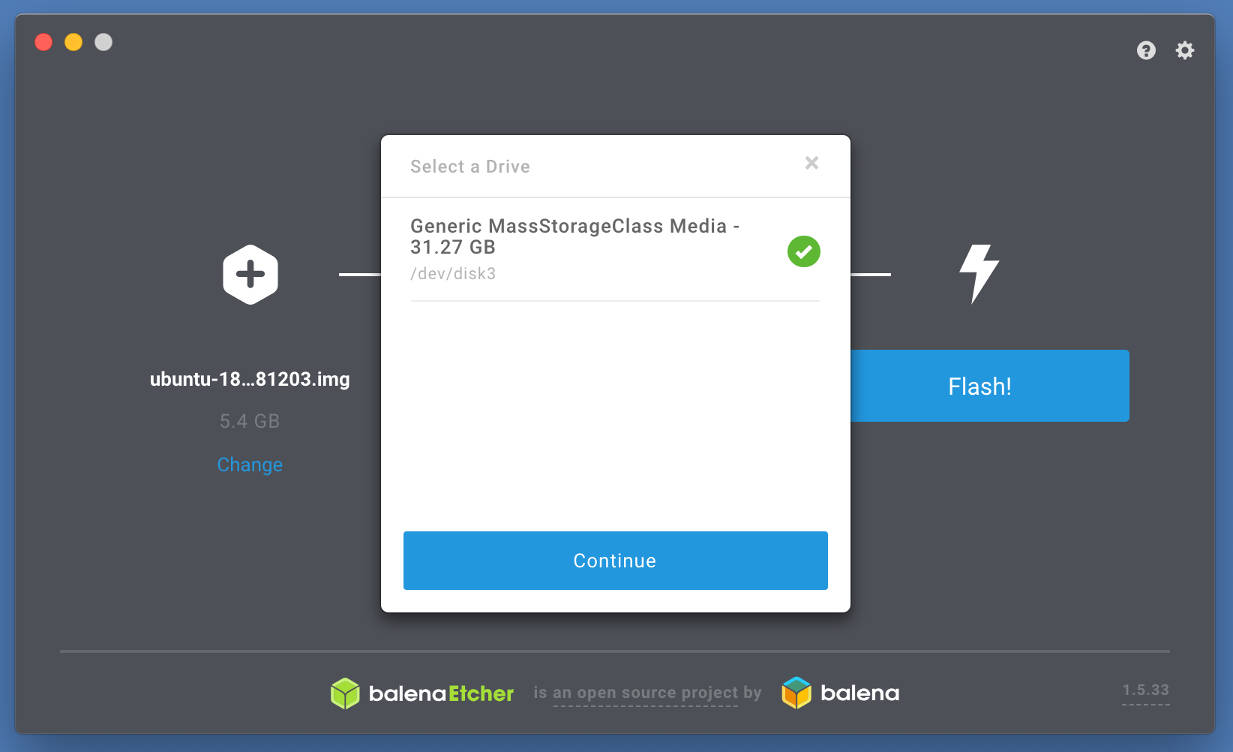
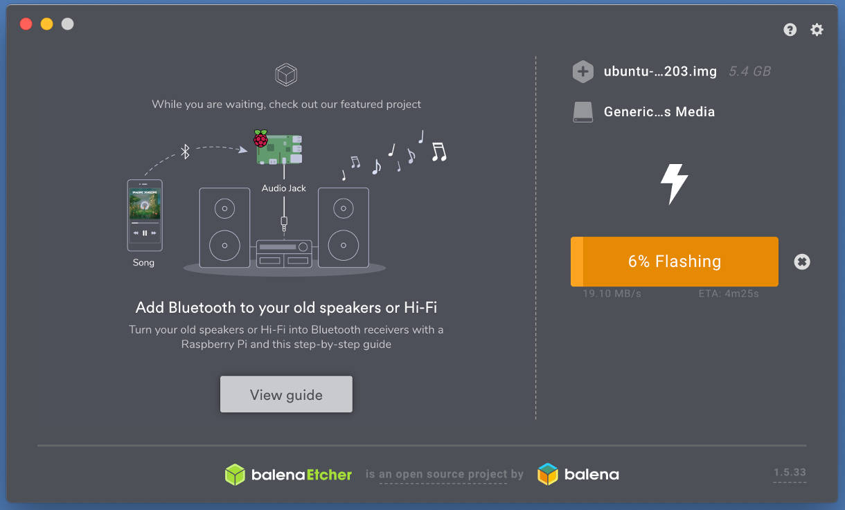
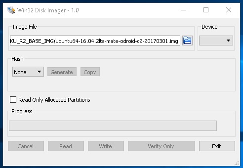
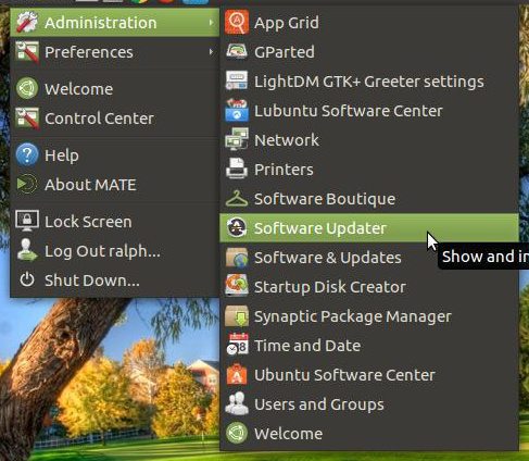
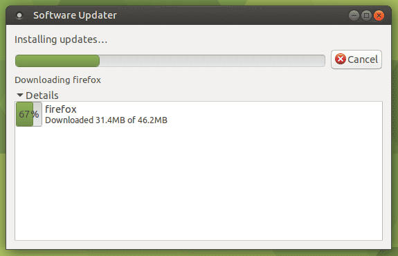
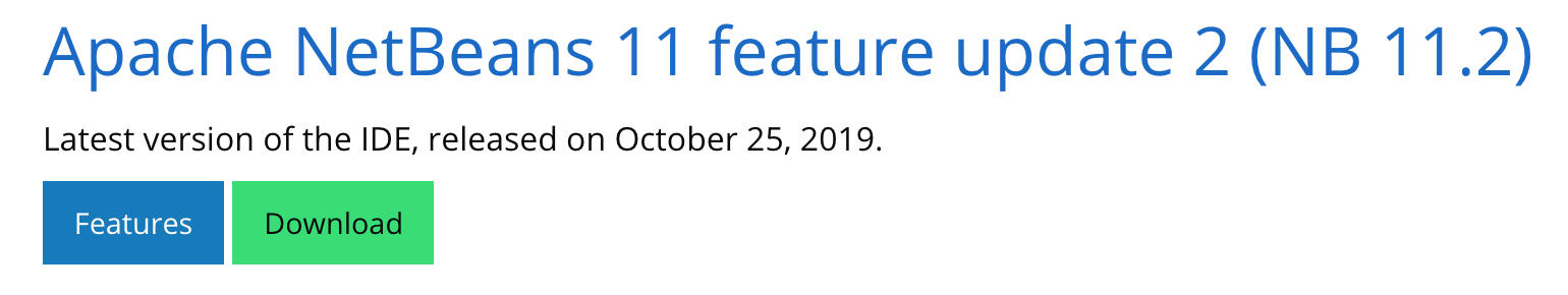
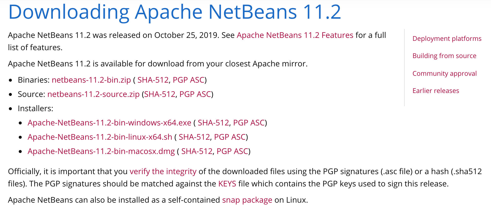
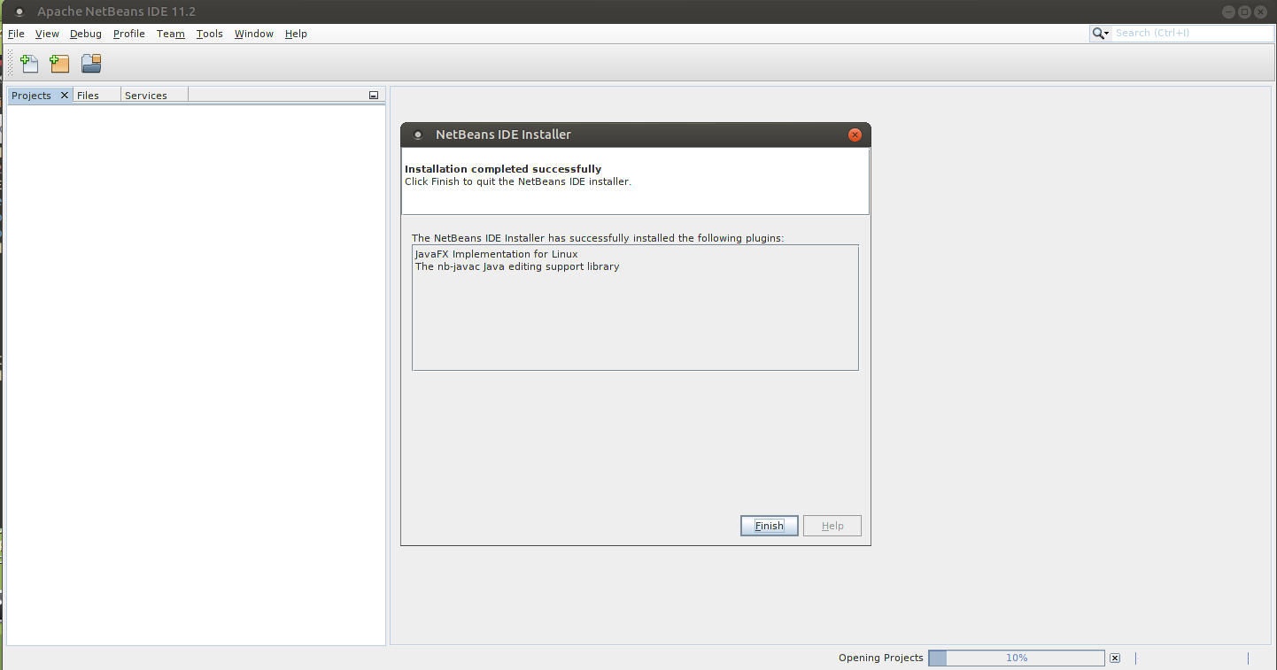
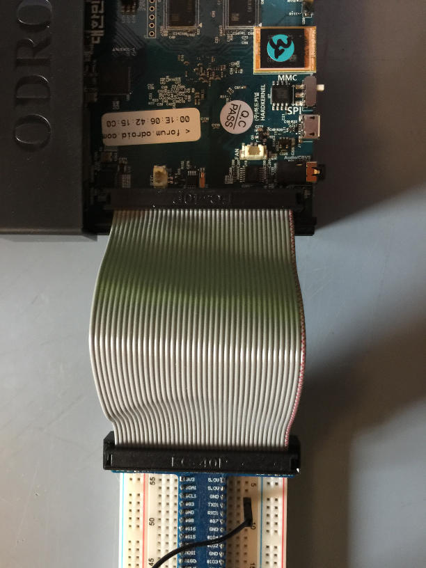
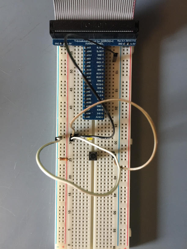
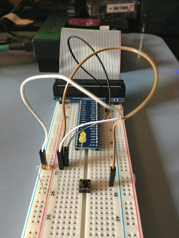
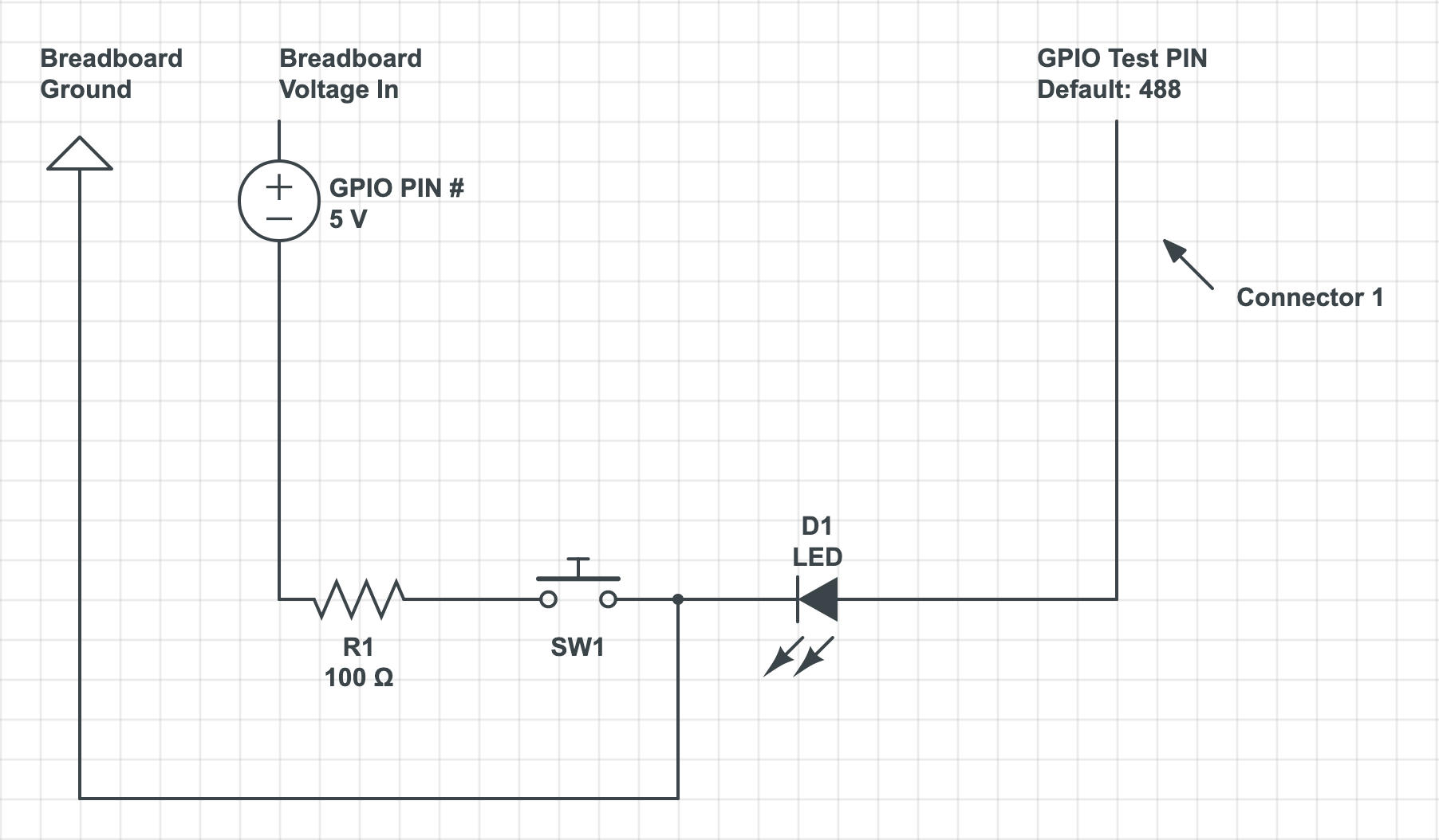
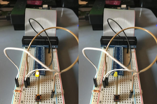
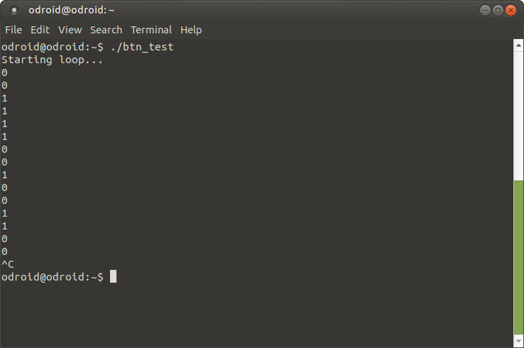
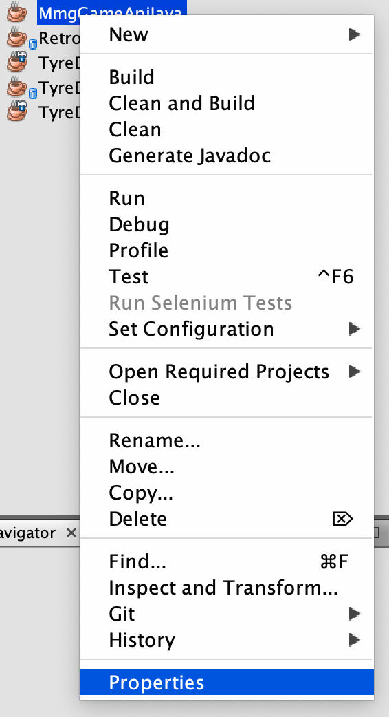
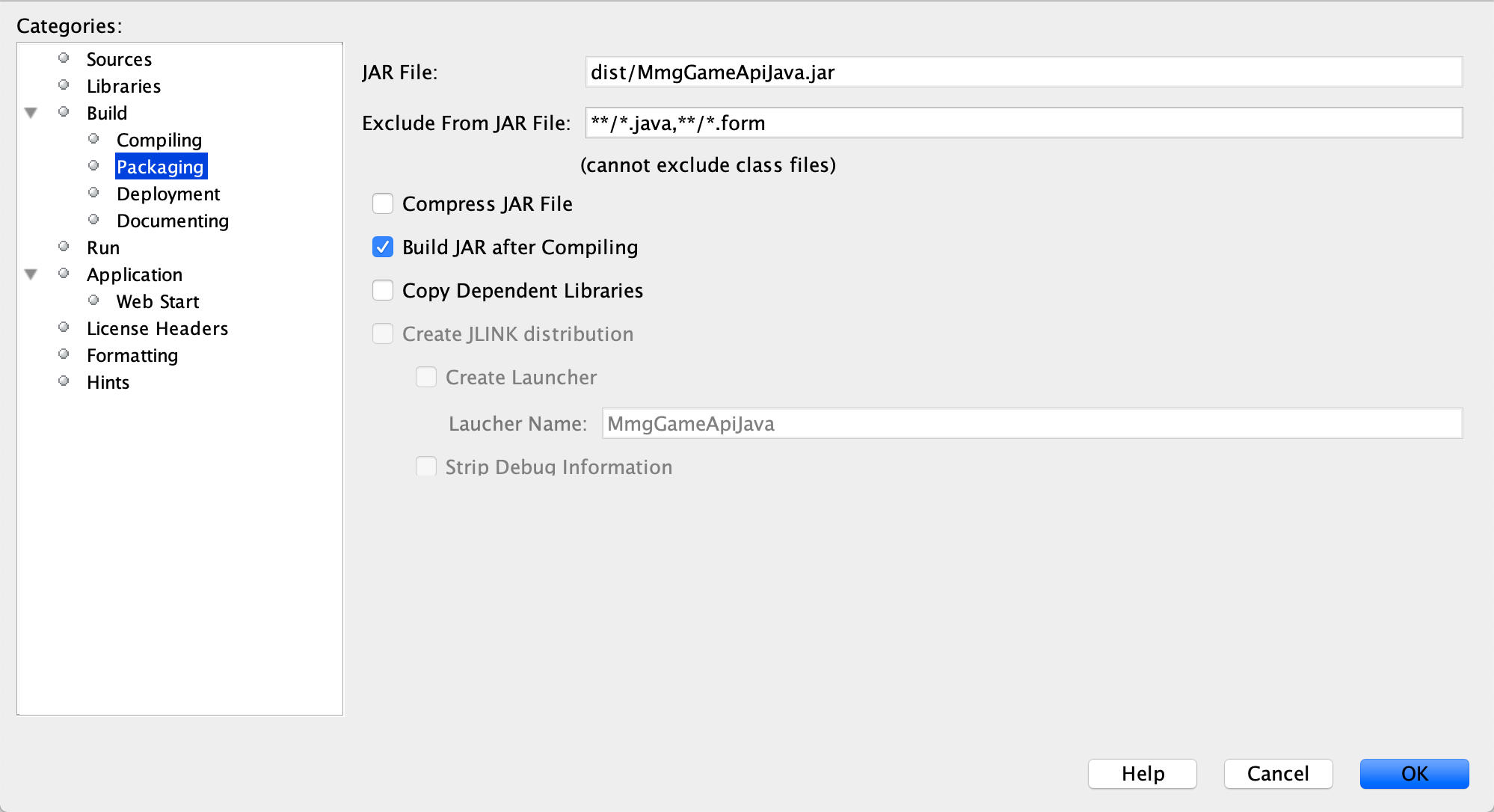
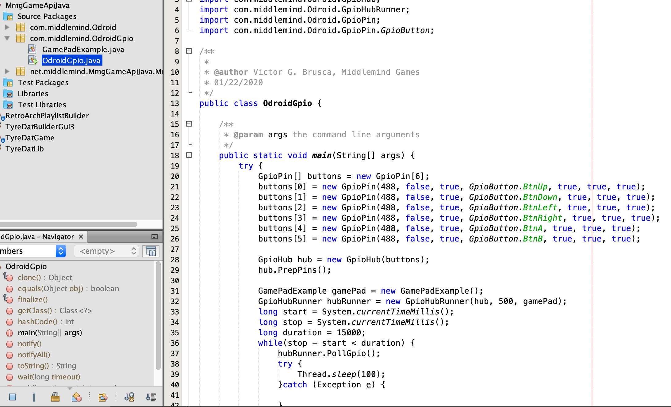
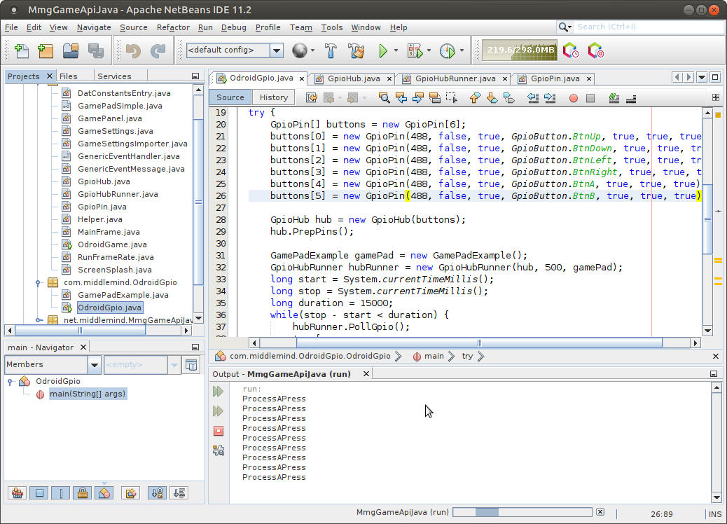
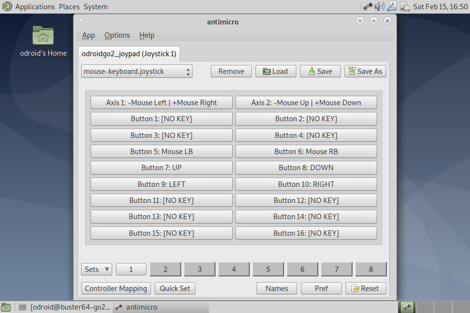
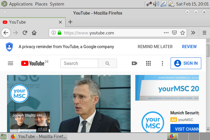

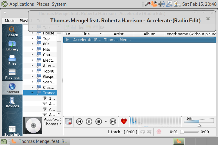
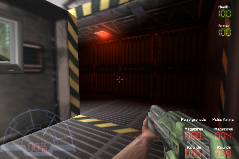
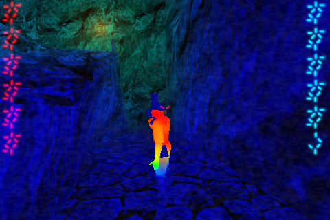
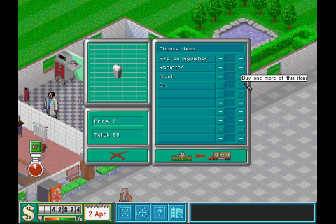
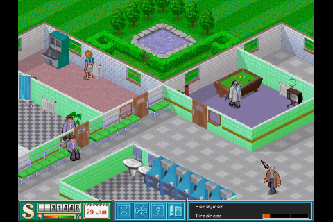
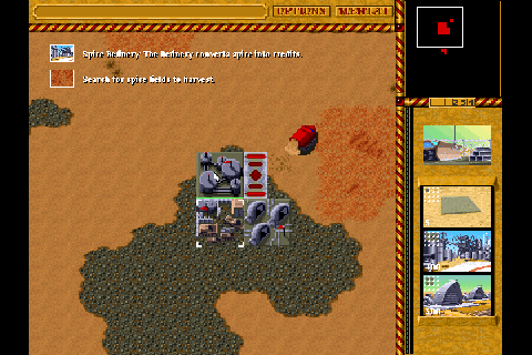
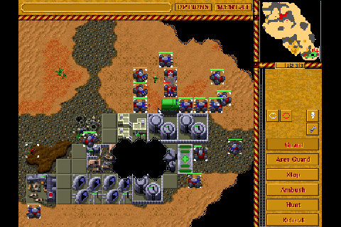
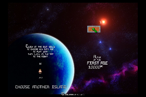
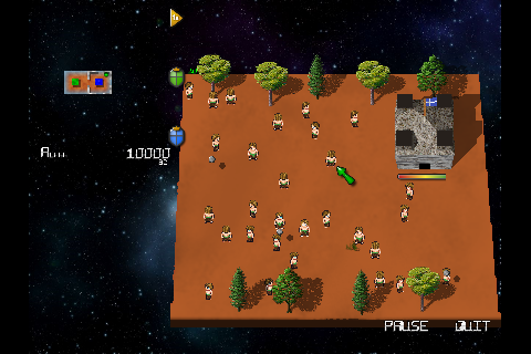
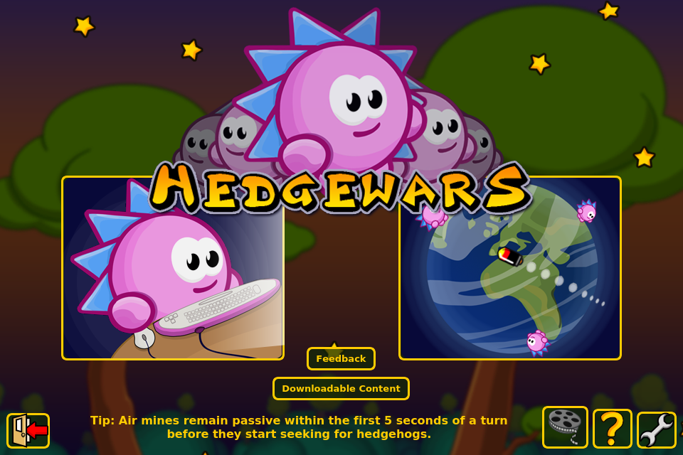
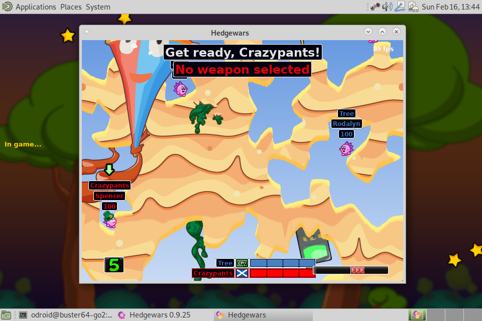
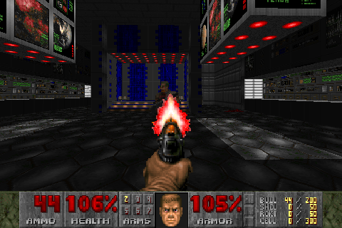
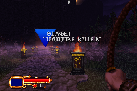
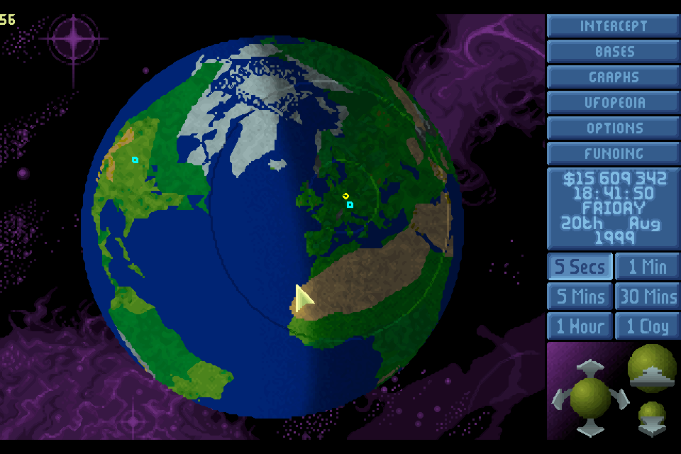
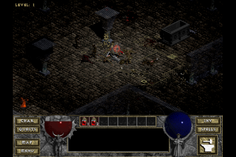
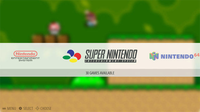
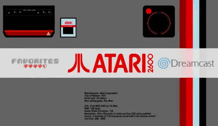
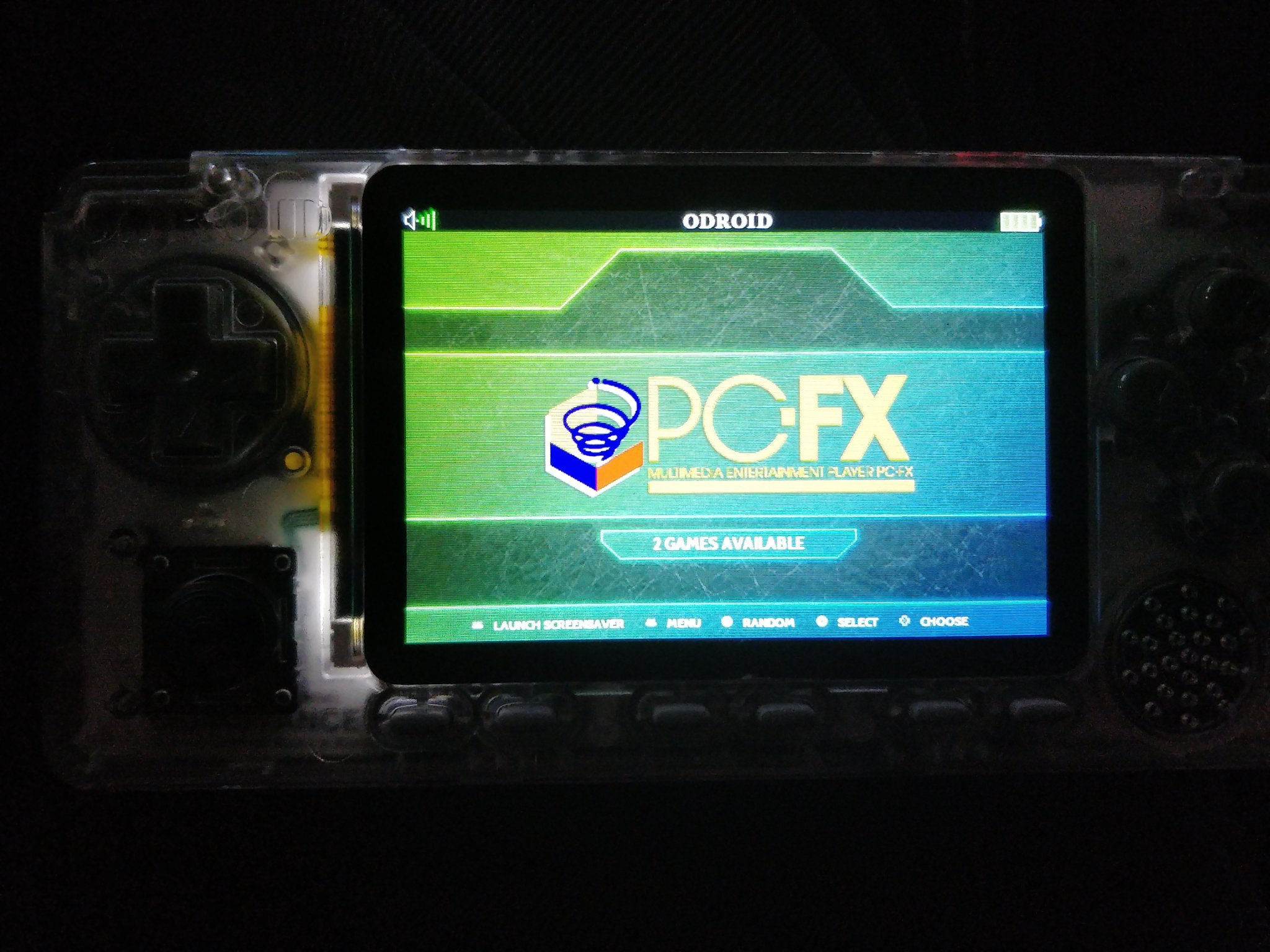
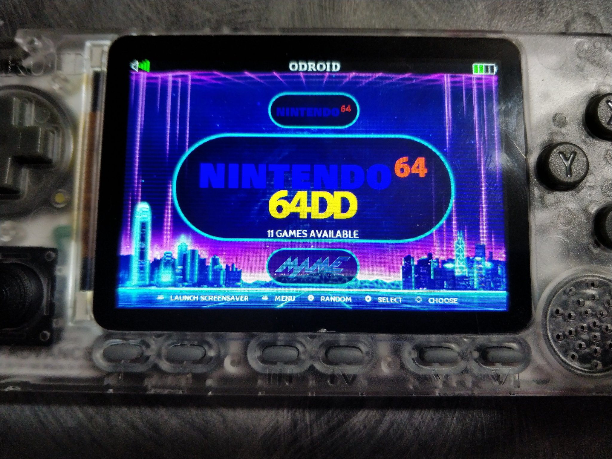
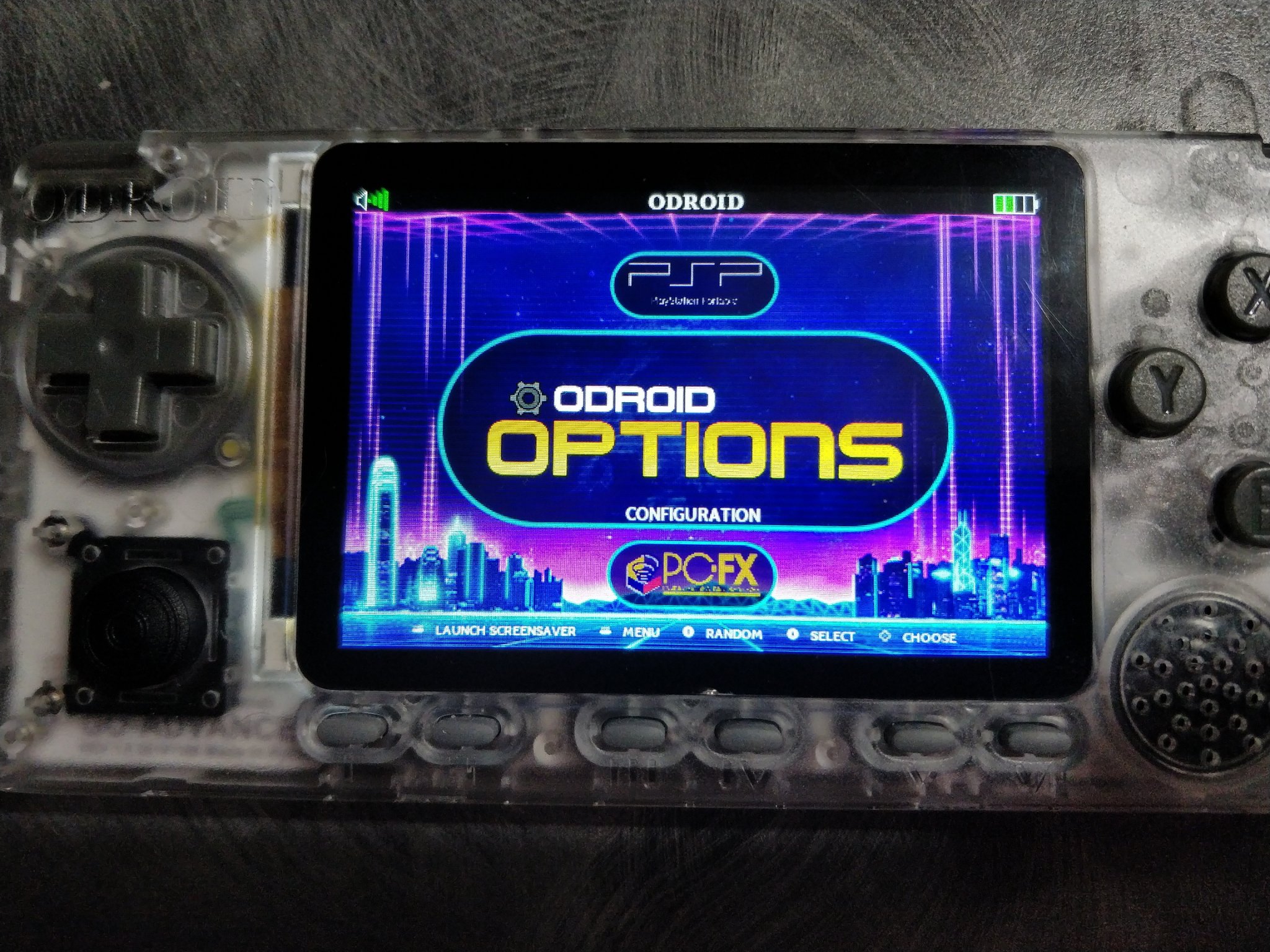
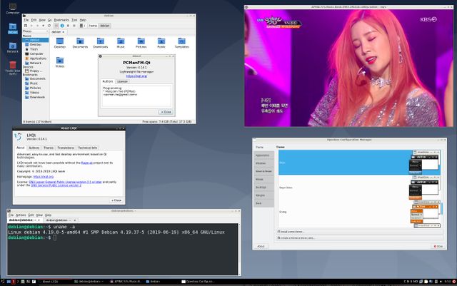
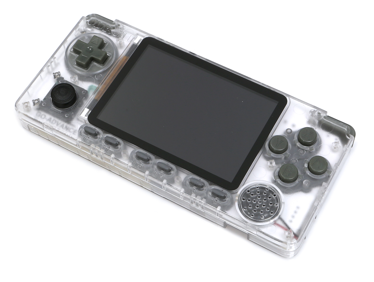
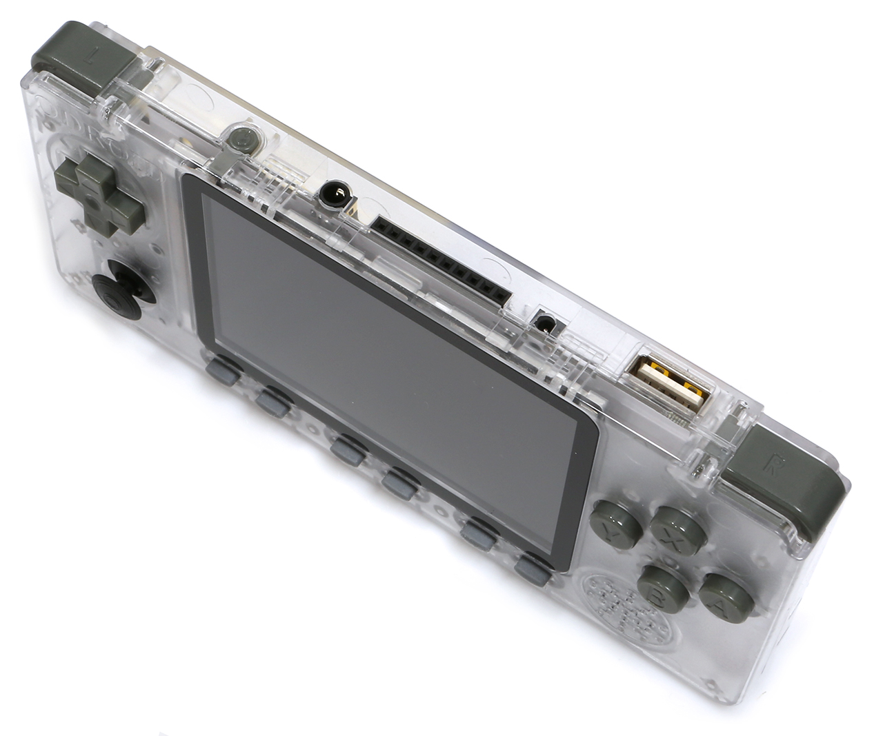
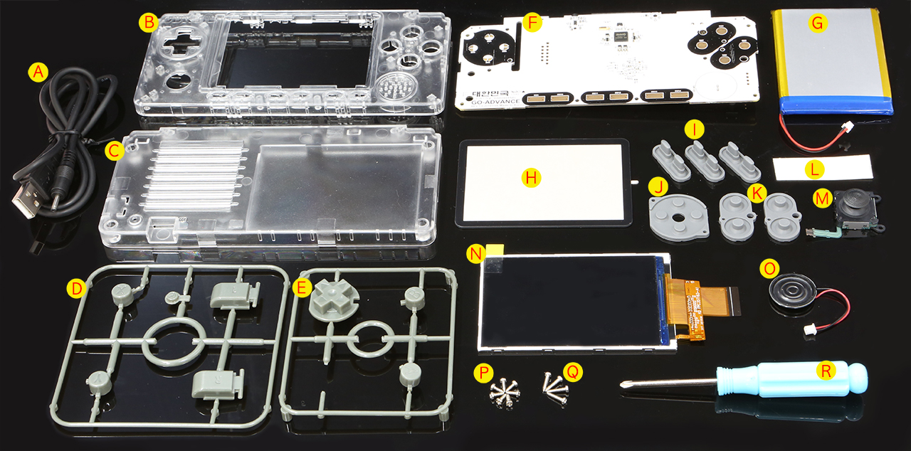