

I have been an electronics enthusiast ever since I was eight years old, when my grandfather used to send me small components such as LEDs, small DC motors, and 555 timers. He would include hand-drawn schematics with notes I could follow in order to build simple projects. As I got older, the projects became more complex, allowing me to learn more. I also got into computers, programming, and Amateur Radio before going to college for computer networking.
Fast forward to 2018: I now make YouTube videos about technology. I started my channel “Kamots Talks Tech” because I had purchased an ODROID-GO and got involved with the community, but I wasn’t happy with the accuracy of most reviews being published about the GO. I wanted to show that this device was better than people were saying, so I made my first video about the GO: a mini-review video about the ODROID-GO. After many more videos, I’m now writing an article to be published, which I have never done before.
My project’s goal is to add wireless charging capabilities to the ODROID-GO. My motivation was utilizing the Qi Wireless Charging pad I already own to make something cool for my YouTube subscribers to enjoy. I was inspired by a video from ETA PRIME where he added wireless charging to the NeoGeo Mini. It may seem like a difficult project but in reality, it’s only four solder connections. If you take your time following the instructions below, you will likely be successful. However, there is risk of damaging your GO so please do not take on this project unless you are confident in your soldering and electronics skills.
Required Supplies
- ODROID-GO (https://bit.ly/2lgWvGA)
- Adafruit’s Universal Qi Wireless Receiver Module (https://www.adafruit.com/product/1901)
- Very thin wire (28AWG / 0.081mm2). I took apart a flat Ethernet cable to get mine
- Electrical tape or other strong non-conductive adhesive
- Soldering iron and solder
Preparation
First, let’s look at portions of the schematic for the ODROID-GO to understand where to connect the Qi coil output. Usually power for the GO is provided via the USB port but the solder pads are very small for the Micro USB connector so we need to find another way to connect on the inside of the GO.
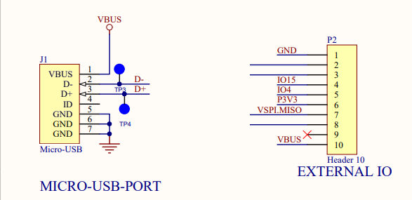
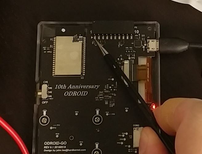
As you can see in Figure 1, power is normally provided to the GO via the Micro USB connector to VBUS and GND. Those same power rails are available on the external IO header which has much larger pins on the GO’s board. So we will solder the Qi module to pin 1 and 10 of the external IO header, which you can see in Figure 2. Standard USB power is 5 volts. The Qi module also provides 5 volts so it will charge the GO just like if you plugged it in via USB.
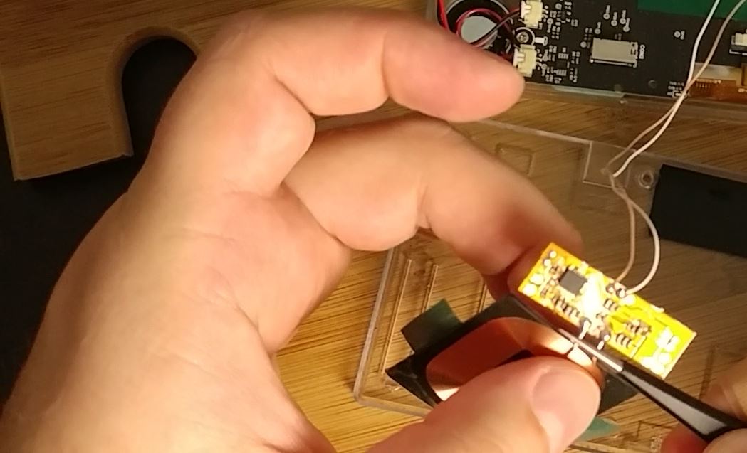
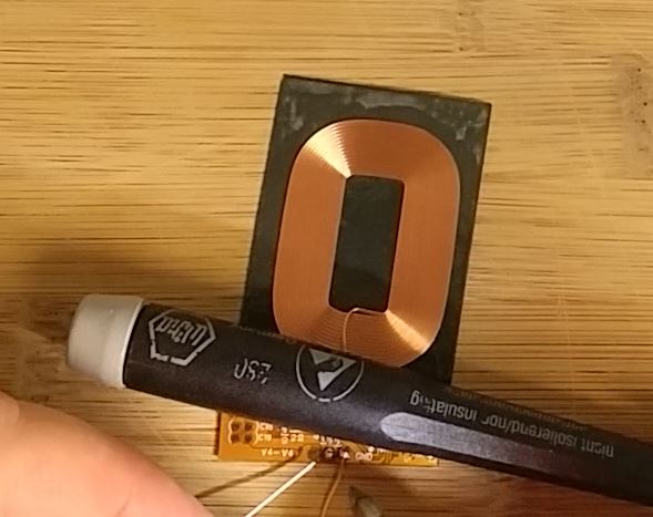
Now that we have figured out where to connect the coil, you will need to very carefully bend the two wires coming from the Qi coil into its controller board. This allows clearance for the plastic ridges on the inside of the GO’s back cover where we will eventually mount the Qi module. I used tweezers to carefully bend the coil feed wires, as you can see in Figure 3. While I myself did this after I had soldered on the wires, I recommend you do it before any soldering.
Making The Connections
Now begins the delicate soldering work. You will want to use the thinnest diameter solder you have. Carefully add a small amount of solder to the V4+ and GND pads on the Qi coil’s controller board as seen in Figure 5. There are three pads and if you have the coil oriented the same way as in Figure 5, you will need to add solder to the center and right pad as shown.

Once you have added solder to the pads, solder one wire to each pad by reflowing the solder you added to the pads and pressing the wire in to it. You can see me do this in Figure 6.
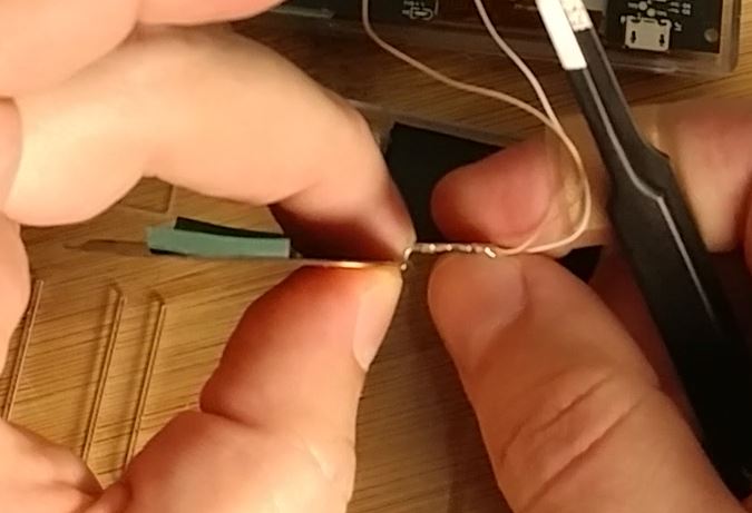
Next, check the length of your wires to make sure they can reach the pins of the external IO header without being so long that they will be difficult to manage when you reassemble the GO. I recommend cutting where the wire reaches my fingers in Figure 7.
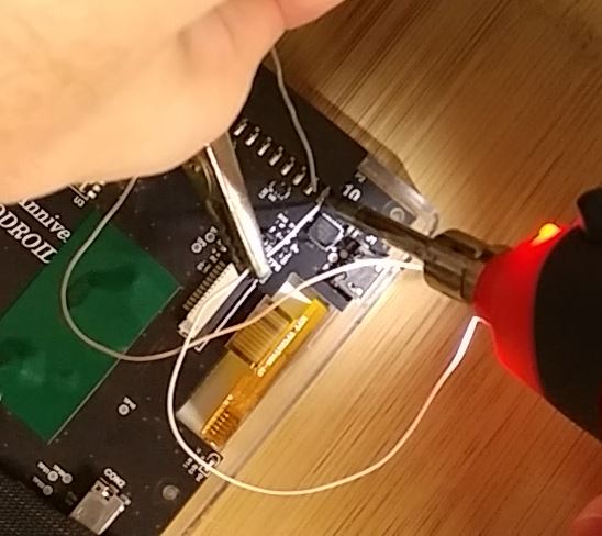
For the next step you will likely need a “Helping Hands” type stand with alligator clips as seen in Figure 8, or an extra set of human hands. You will need to position the wires on the header pins, heat the header pin and wire, then add solder to make a good connection. As you may remember from the schematic in Figure 1, the wire from V4+ goes to pin 10 and the wire from GND goes to pin 1. Be very careful when soldering wire to pin 1 as the nearby component could get damaged.
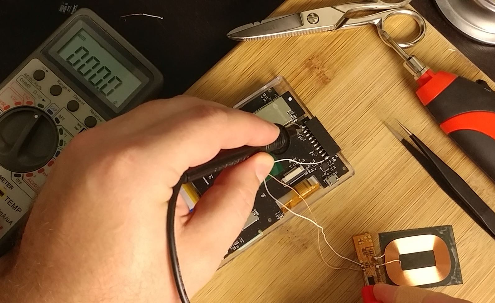
Test your connections with a multimeter, making sure you have good connections with no resistance. Verify that you have connected the Qi coil output pins to the correct pins on the GO. Getting things backwards could damage your device and/or the Qi coil controller board.
Finishing Up
Once you are certain everything is connected properly, grab your Qi charging pad and place the Qi coil on it as seen in Figure 10. The red light on the GO should be illuminated, indicating that it is charging.
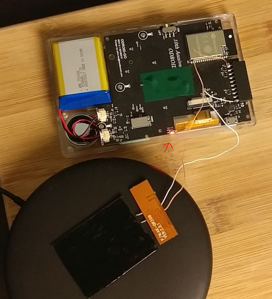
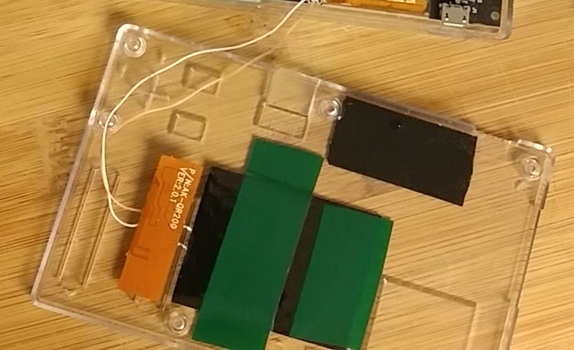
If it works, celebrate! The hard part is over. Now you just need to secure the Qi coil to the back case of the GO. I used electrical tape as you can see in the pictures. However, Justin Thomas left a comment on my video about this project saying I should try 3M brand VHB double-sided tape. I’ll leave it up to you which one you use. The most important part is making sure that the coil lays flat against the inside of the back cover and that you don’t damage it. You may also want to cut away part of the plastic ridges inside the back cover around where the Qi coil controller board sits before securing the coil. You can see how I secured mine in Figure 11.
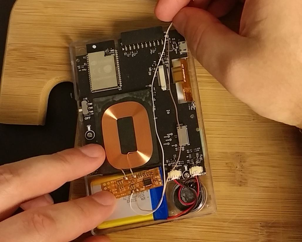
Once you have the Qi coil and its board secured to the back panel, close up the GO--making sure the wires are not pinched anywhere--and put all of the screws back in place. The final result should look similar to Figure 12.
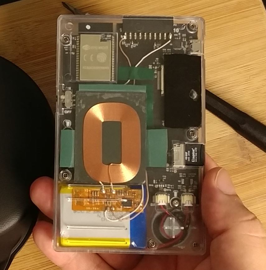
Now you can place your GO on a Qi charging pad, making sure you center the coil on the pad, and enjoy wirelessly charging the GO. I did notice the coil gets a little warm after a while, but I don’t think it is an issue. However, the coil can’t tell when the GO finishes charging, so don’t leave it on a charging pad overnight. You can also still use a USB cable to charge your GO if you want.
Be the first to comment