

This article describes how to setup a GPIO key button for power off and wake up purposes. The brief setup steps include the following:
- Connecting a tab button to the pin port you want to use
- Setting the GPIO number using boot.iniCompiling and flashing the modified kernel
- DTS, which is only needed for Android
Hardware Setup
First, you need to prepare a tab switch that will be connected to two GPIO lines. The red wire will be for power and the gray wire will be for the active level line (ground or 3.3V power).
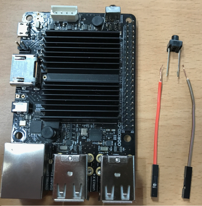
The ODROID-C2 pin layout diagram at http://bit.ly/2aXAlmt will come in very handy for this project. In our case, we will use Pin# 29 of the 40-pin expansion connector. The pin is assigned to GPIOX.BIT0 and its GPIO number is 228. Connect the red line to Pin# 29. Its default pin pulled status is high and switch active will be low. So, you should connect the gray line of tab switch to Ground (GND), Pin# 30.
| Pin Number (Red Line) | GPIO Number | Active Level (Gray Line) |
| 29 | GPIO# 228 | Active Low (Pin 30) |
Available Keys
Here are the available key examples on the 40-pin connector and 7-pin connector. You can find the pin assign examples for Red Line and Gray Line. (1) J2 - 2×20 pins
| Active Level (Gray Line) | GPIO # | Pin # (Red Line) | Pin # (Red Line) | GPIO # | Active Level (Gray Line) |
| - | 3.3V Power | 1 | 2 | - | - |
| - | - | 3 | 4 | - | - |
| - | - | 5 | 6 | Ground | - |
| Active Low (Pin 9) | GPIO# 249 | 7 | 8 | - | - |
| - | Ground | 9 | 10 | - | - |
| Active Low (Pin 14) | GPIO# 247 | 11 | 12 | GPIO#238 | Active Low (Pin 14) |
| Active Low (Pin 14) | GPIO# 239 | 13 | 14 | Ground | - |
| Active Low (Pin 14) | GPIO# 237 | 15 | 16 | GPIO#236 | Active Low (Pin 14) |
| - | 3.3V Power | 17 | 18 | GPIO#233 | Active Low (Pin 20) |
| Active Low (Pin 20) | GPIO# 235 | 19 | 20 | Ground | - |
| Active Low (Pin 20) | GPIO# 232 | 21 | 22 | GPIO#231 | Active Low (Pin 20) |
| Active Low (Pin 25) | GPIO# 230 | 23 | 24 | GPIO#229 | Active Low (Pin 25) |
| - | Ground | 25 | 26 | GPIO# 225 | Active High (Pin 17) |
| - | - | 27 | 28 | - | - |
| Active Low (Pin 30) | GPIO# 228 | 29 | 30 | Ground | - |
| Active Low (Pin 30) | GPIO# 219 | 31 | 32 | GPIO# 224 | Active Low (Pin 34) |
| Active High (Pin 17) | GPIO# 234 | 33 | 34 | Ground | |
| Active Low (Pin 34) | GPIO# 214 | 35 | 36 | GPIO# 218 | Active Low (Pin 34) |
| - | - | 37 | 38 | - | - |
| - | Ground | 39 | 40 | - | - |
(2) J7 - 1×7 pins
| Pin # (Red Line) | GPIO # | Active Level (Gray Line) |
| 1 | Ground | - |
| 2 | GPIO# 128 | Active Low (Pin 1) |
| 3 | 5.0V Power | - |
| 4 | GPIO# 130 | Active Low (Pin 1) |
| 5 | GPIO# 132 | Active Low (Pin 1) |
| 6 | GPIO# 131 | Active Low (Pin 1) |
| 7 | GPIO# 133 | Active Low (Pin 1) |
You can find the detailed information about 40-pin and 7-pin expansion connectors at http://bit.ly/2gzCA7c.
Ubuntu software setup
The release version should be 3.14.79-107 (Feb 26, 2017) or higher. You can assign GPIO number with env gpiopower in boot.ini:
## gpio power key : J2 (2x20) Pin#29 , GPIOX.BIT0
setenv gpiopower "228"
...
## Add gpiopower like "setenv bootargs ${bootargs} gpiopower=${gpiopower}"
setenv bootargs "root=UUID=e139ce78-9841-40fe-8823-96a304a09859 rootwait ro ${condev} no_console_suspend hdmimode=${m} ${cmode} m_bpp=${m_bpp} vout=${vout} fsck.repair=yes net.ifnames=0 elevator=noop disablehpd=${hpd} max_freq=${max_freq} maxcpus=${maxcpus} monitor_onoff=${monitor_onoff} disableuhs=${disableuhs} mmc_removable=${mmc_removable} usbmulticam=${usbmulticam} ${hid_quirks} gpiopower=${gpiopower}"
Setting Power Button Action for Power Off
If you intend to turn the board off using the power button, you will need to change the power key action pattern. To facilitate that, first open the Power Management Preferences dialog ([System] → [Preferences] → [Hardware] → [Power Management]) and select the [General] tab.

Wake up Action
To wake the system up after power off, a long-duration (2-3 seconds) pressing of the power button is needed.
Android software setup
In Android, you have to modify the DTS file in Android Marshmallow (v2.4) and higher version to use this functionality.
You will have to modify the DTS file to activate the GPIO key functionality:
/arch/arm64/boot/dts/meson64_odroidc2.dts
...
gpio_keypad{
    .
    status = "okay";
    .
};
…
After compiling the DTS file, you can flash the DTB file to the board:
$ make odroidc2_defconfig
$ make dtbs
$ fastboot flash dtb arch/arm64/boot/dts/meson64_odroidc2.dtb
$ fastboot reboot
You have to flash the DTBS file when the board is in u-boot fastboot mode:
$ reboot fastboot
Setting boot.ini
In the Android boot.ini, you can uncomment the “gpipower” entry and modify the number to the number relevant in your case:
## gpio power key : J2 (2x20) Pin#29 , GPIOX.BIT0
setenv gpiopower "228"
Setting Power Button Action for Power Off
In Android, you do not need to select any menu options for power button actions. It is already defined as follows:
One short power key event is used for sleep, and with long key event, you can handle options of power off/reboot.
With Android Marshmallow v2.4 or higher version, it is possible to enter power off using a long-duration press (5 seconds).
Wake up Action
To wake-up after power off, a long-duration press (2-3 seconds) will be needed.
Troubleshooting
You can refer to the forum posts at http://bit.ly/2gtE4MA and http://bit.ly/2zGwB4X for troubleshooting tips. For comments, questions, and suggestions, visit http://bit.ly/2yYFWrB.
Be the first to comment