This guide will show you how to download and compile the Android kernel for ODROID-XU3/XU4. If you have not built Android on your desktop yet, please read Google’s official build environment setup guide at http://bit.ly/1Hd3Z3P. Carefully review this before you proceed, or you may have unexpected errors and will need to read through long and complicated build logs to find the problem.
We used Ubuntu 14.04 64bit with 8GB of RAM since other newer versions of Ubuntu have had some issues while building the Android OS. http://bit.ly/2yGT5Tw If you want to build the full Android source tree, don't download and build the kernel source separately. A separated Kernel build might break the Android build process.
Install the openjdk-8-jdk
If your build environment is Ubuntu 14.04 or 12.40, enter the following:
Please note that we distribute the Linux kernel in different branches for Android and other Linux distributions.
Android platform and kernel
The repository is available for download at http://bit.ly/1Syr1sf. Android’s full downloaded source code size is around 70GB, so make sure to prepare enough space before building the Android platform:
Before compiling, you must configure the ODROID-XU3 with the following commands.
$ ./build.sh odroidxu3
Once you complete the long build process, the img files can be found in the “/tmp/odroidxu3/” directory. To use ADB over a TCP/IP connection, please refer to http://bit.ly/2gtWzAo.
Installation for ODROID-XU3/XU3-Lite
There are different instructions for installing a Linux kernel image for Android and Linux. Since Android loads both from a kernel partition, we have to use fastboot to install into the dedicated partition. Before beginning, please refer to the partition table at http://bit.ly/2irbjnC. By contrast, Linux boots by the instructions described in boot.ini on the 1st FAT partition.
First, install the kernel image zImage-dtb, onto the boot board:
You can avoid using fastboot on an ODROID-XU4, because it doesn't have an USB OTG port. First, setup an ADB connection or copy an image to the FAT partition:
$ adb push xxxx.img /sdcard/
$ adb reboot
View the U-Boot logs by connecting to the ODROID-XU4 with a USB-UART kit:
U-Boot 2017.05-12209-g43745f3 (Aug 17 2017 - 09:37:39 +0900) for ODROID-XU4

CPU: Exynos5422 @ 800 MHz
 Model: Odroid XU4 based on EXYNOS5422
 Board: Odroid XU4 based on EXYNOS5422
 Type: xu3
 DRAM: 2 GiB
 MMC: EXYNOS DWMMC: 0, EXYNOS DWMMC: 1
 MMC Device 0 (eMMC): 14.7 GiB
 Info eMMC rst_n_func status = enabled
 MMC Device 1 ( SD ): 7.4 GiB

*** Warning - bad CRC, using default environment

In: serial
 Out: serial
 Err: serial
 Net: No ethernet found.
 Press quickly 'Enter' twice to stop autoboot: 0
Type the following commands after pressing “Enter” twice to pause the booting process:
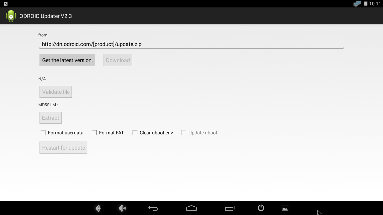
You can update from Stock Android Kitkat 4.4.4 to Android 7.1 using the ODROID Updater verison 5.6 or higher (http://bit.ly/2yFz9lf). Always check the option “Format userdata” when updating from other Android revision, as shown in Figure 1.
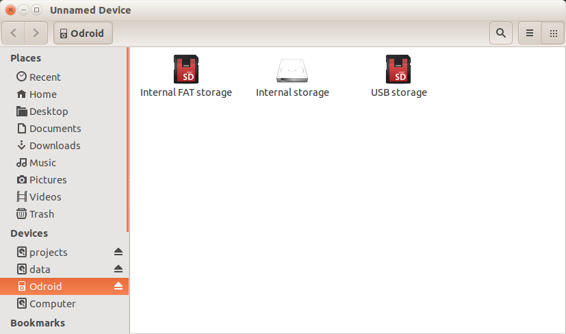
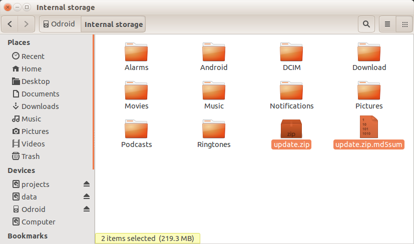
Open “Internal storage”, as shown in Figure 2, then copy update.zip and update.zip.md5sum as shown in Figure 3. Enable the “Validate file” button as shown in Figure 4.
Figure 2 - Opening the Internal Storage link in LineageOS
Figure 3 - Selecting the update.zip and update.zip.md5sum files
Figure 4 - Validating the update files in the ODROID Updater
Storage Information
/storage/sdcard0 fat partition of eMMC or microSD INTERNAL STORAGE /storage/sdcard1 microSD slot SD CARD
/storage/usb2host USB 2.0 Host port USB STORAGE
/storage/usb3host USB 3.0 Host port USB STORAGE
/storage/usb3device USB 3.0 Device port USB STORAGE
For comments, questions, and suggestions, please visit the original article at http://bit.ly/2yUeqvm.
ODROID-Powered LIDAR: Light Detection and Ranging with the ODROID-XU4
November 1, 2017By Tom JacobsODROID-XU4, Tinkering
I just recently ordered an ODROID-XU4 to power my latest project, an Earth Rover, which is a 6-wheeled rover, with the aim to navigate inside and outside areas autonomously. I'm using a LIDAR pulled out of an old robotic vacuum cleaner, the Neato XV-11 LIDAR. This project covers interfacing the ODROID with the LIDAR, receiving scan measurements, and integrating them into a SLAM, Simultaneous Localisation and Mapping, system for building a map of the area. I chose the ODROID because it was the only board powerful enough to process the measurements into a map in real time.
It has eight cores, four run at 2Ghz, and four run at 1.6Ghz. Remember your original Pentium 133Mhz? This thing runs fifteen times faster than it, and does it four times at once— and has another four cores just for kicks, and it fits inside your coffee cup. How much is it? $59.
Plug it in, HDMI, power, USB keyboard & mouse, USB wifi. And first up, run the following commands to completely update your system:
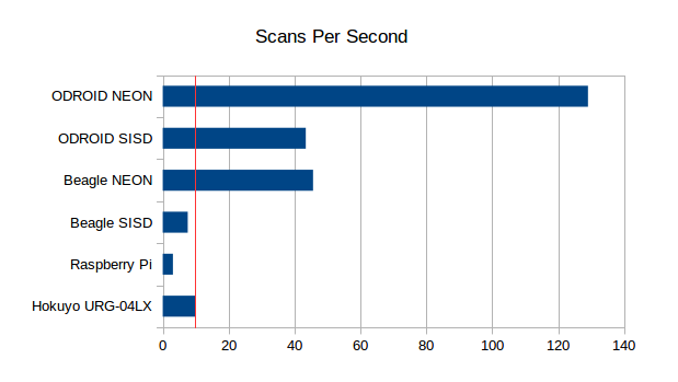
Due to the NEON multi-processing instruction set, the performance is quite good, http://bit.ly/2zG12Ix, for particular tasks such as SLAM, even compared to the powerful Pi, as shown in Figure 1.
Figure 1 - Scans Per Second comparison for various SBC devices
Now we have lots of good applications such as Python, PIP, OpenCV, FFMPEG, and Alsa, let’s install BreezySLAM:
$ git clone https://github.com/simondlevy/BreezySLAM
$ cd BreezySLAM/python
$ sudo python setup.py install
$ cd ../examples
$ make pytest
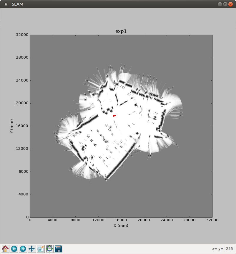
Figure 2 - A preliminary image of a SLAMed room using LIDAR
As shown in Figure 2, we’re seeing a SLAMed room! This is from its built-in data file, so no external physical LIDAR is available yet. Let’s try watching the thing run live, which requires matplotlib:
$ sudo apt-get install python-matplotlib
$ make movie
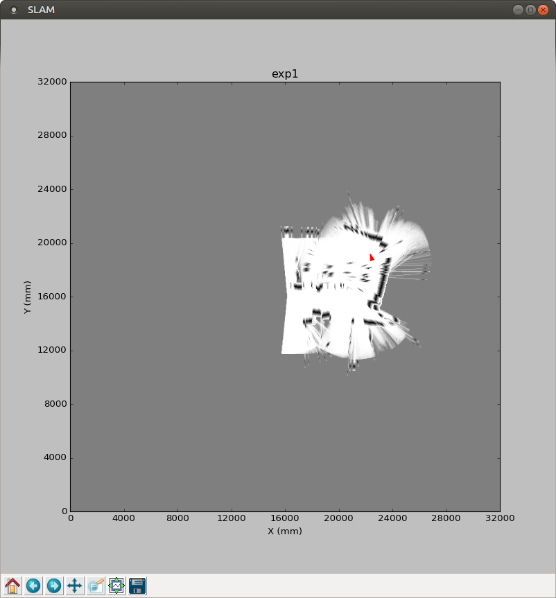
Figure 3 - A live movie version of a SLAMed room using LIDAR
As shown in Figure 3, we can see it run, and a map is being generated. The next step is to try out the LIDAR, which requires xvlidar, pip, and pyrserial:
Since it’s trying to access the serial port, we can check that device:
$ ls /dev/tty*
$ /dev/ttyACM99
It turns out that the device is actually in another port:
$ /dev/ttySAC0
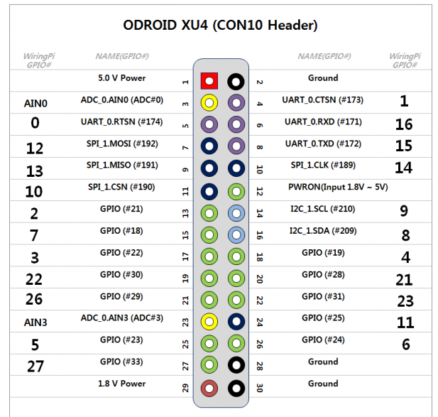
To find out where to plug the LIDAR, we can refer to the ODROID-XU4 manual at http://bit.ly/2xYZhco, but it’s not mentioned. The information that we need is at http://bit.ly/2hYj8NQ, and Figure 4 illustrates the pins that we are looking for.
Figure 4 - GPIO configuration for a LIDAR project on the ODROID-XU4
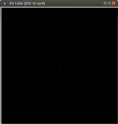
The receive and transmit pins are UART_0.RXD (#6) and UART_0.TXD (#8). Let’s take a ground (#2) and a 5v power (#1) as well. Most XV Lidars are 5v, as described at http://bit.ly/2gBSiPc. I used the 1.8v pin to power the LIDAR motor, which hopefully supplies enough amperage. After running lidarplot.py again, I get a spinning lidar, and a blank plot with a single dot in it, and the occasional “Checksum fail” when I wiggle the plugs. So it’s getting something, but not anything useful yet, as shown in Figure 5.
Figure 5 - The initial output of the LIDAR configuration on the ODROID-XU4
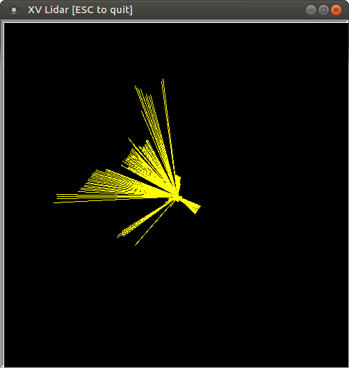
After adding some printouts, I see that the serial port is generating lots of 82’s along the 360 degree array. I assume that means “Not spinning fast enough”, because I used a Raspberry Pi 2 to generate the correct voltage at 3.3v, and was able to get LIDAR scans. It also updates very quickly, since when I put my hand in front of it, the change is reflected within a second or so.
Figure 6 - The tweaked output using a 3.3v motor of the LIDAR configuration on the ODROID-XU4
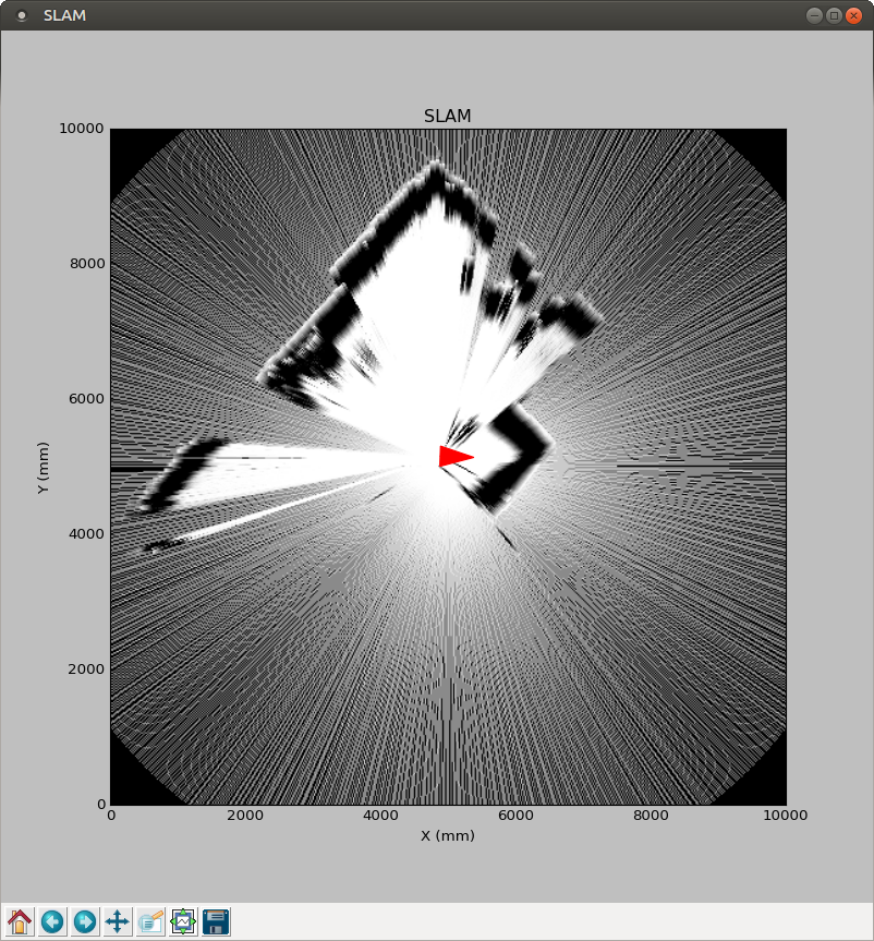
Now we are ready to run the SLAM application:
$ cd BreezySLAM/examples
$ python xvslam.py
Figure 7 - SLAM on the ODROID-XU4
For comments, questions, and suggestions, please visit the original article at: http://bit.ly/2xX6ObL.
LEMP stack web server: Linux, NGINX, MariaDB, and PHP on the ODROID-HC1
November 1, 2017By Justin LeeLinux, ODROID-HC1, ODROID-HC2
This guide will let you build an inexpensive but powerful web server using an ODROID-HC1 (XU4 family, including the ODROID-HC2) fitted with a SATA-based SSD.
Prepare boot media
Before you proceed to build the web server, burn the latest official Hardkernel Ubuntu Minimal image onto your boot media - 8GB+ Class 10 microSD card. A Hardkernel offered eMMC may also be used, in conjunction with a USB3 microSD card reader.
Go to the http://bit.ly/2xaucO8 link and download the latest Ubuntu Minimal image. Also, access the https://etcher.io/ link and download the appropriate version of Etcher for your operating system. Insert your microSD card in your computer and run Etcher, then burn the image onto your microSD.
Set up your ODROID
Install the SSD using the SATA port on your ODROID-HC1. Make sure you use the official 5V 4A+ Hardkernel PSU, to ensure the SSD has adequate power. Once this is done, insert the prepared boot disk into your ODROID and turn on the power to the ODROID-HC1.
The first boot can take about 5 minutes to initialize the OS. If it does not turn on after about 5 minutes, you can reboot it by turning the power off, disconnecting the power cord, re-plugging the power cord and turning the power back on.
Note that if you use an ODROID-XU4, you can build a high performance NAS using a powered USB hub, one SSD/eMMC for the operating system, and one or more hard drives for the NAS. Bus-powered hubs may not work well, due to inadequate power.
SSH Access and system update
Connect to your ODROID-HC1 via SSH and build your web server. It is highly recommended to update the image on the microSD card. That will let you take advantage of the latest fixes and possible support for additional features. After SSH access, update Ubuntu and the kernel with the following commands:
Boot media such as the microSD card makes for an inefficient system because the microSD card will be slow (for the OS and applications running on it, such as the web server) and subject to early failure after excessive writes. Although an eMMC is a viable option for an ODROID-XU4, it is not available for the ODROID-HC1. Therefore, the installation and use of an SSD is highly recommended for hosting websites using databases. To efficiently use the SSD for boot up and applications, follow the step by step guide below to prepare your SSD with a root partition. You can refer to the forum post at http://bit.ly/2gpT9OR for additional details.
Re-partition your SSD
First, you should partition your SSD to use two partitions: one as the root partition for the OS, and the other for data. Obtain information on your SSD using the fdisk tool:
To partition the SSD, use the fdisk tool with entering proper device name (/dev/sda as noted in the output earlier):
$ sudo fdisk /dev/sda
The useful fdisk-options are listed below:
p : print the partition table
n : add a new partition
d : delete a partition
w : write table to disk and exit
q : quit without saving changes
g : create a new empty GPT partition table
m : help (menu)
While referring to the menu above, delete current partitions, if any, and create a new GPT partition table. Then create one new partition for a root partition, and another new partition for a data. In our case, the root partition has a capacity of 16G and the rest is a data partition. You can specify the capacity of the partition by typing a capacity unit, for example, “+16G”.
Check the result of your actions by obtaining partition using the “p” option. If the partition information match your intentions, then press “w” to save and exit.
# In fdisk
Command (m for help): p
Disk /dev/sda: 111.8 GiB, 120034123776 bytes, 234441648 sectors
Units: sectors of 1 * 512 = 512 bytes
Sector size (logical/physical): 512 bytes / 4096 bytes
I/O size (minimum/optimal): 4096 bytes / 33553920 bytes
Disklabel type: gpt
Disk identifier: 0412F7EC-4E8C-4610-ABFF-D6293387ADB6

Device        Start       End   Sectors  Size Type
/dev/sda1      2048  33556479  33554432   16G Linux filesystem
/dev/sda2  33556480 234441614 200885135 95.8G Linux filesystem
Format and mount as an EXT4 partition
A modern Linux system typically uses an EXT4 file system, so it is advisable to create ext4 type partitions:
Note down the UUID for /media/systemdrive, then change the UUID of the root file system in boot.ini so that your bootloader recognizes the SSD's partition as a root partition:
$ sudo cp /media/boot/boot.ini /media/boot/boot.ini.bak
$ sudo vi /media/boot/boot.ini
Search for the phrase “Basic Ubuntu Setup” in the file:
...
# Basic Ubuntu Setup. Don't touch unless you know what you are doing.
# --------------------------------
setenv bootrootfs "console=tty1 console=ttySAC2,115200n8 root=UUID=e139ce78-9841-40fe-8823-96a304a09859 rootwait ro fsck.repair=yes net.ifnames=0"
…
Change the root UUID to match the above value. Note that your UUID values may be different from what is mentioned here.
Updating fstab
To mount your partitions automatically, add needed entries in the /etc/fstab file.
As shown above, sda1's MOUNTPOINT is “/”, which means that the system booted from SSD successfully.
LEMP (Linux, NGINX, MariaDB, PHP) stack
We have opted to use nginx for the web server. It uses an asynchronous, event‑driven approach to handling connections, which is fast and has room for serving requests from many users, as well as offering reliable performance. It has been designed to be lightweight software that offers many features. If you wish to avail use features as addon modules, Apache would be a better choice.
PHP
To install PHP, you should add a repository for PHP in advance. And you can install latest PHP for ARM, version 7.1 or above.
Once the installation is done, you should change timezone specified in a setting file of PHP.
$ sudo vi /etc/php/7.1/fpm/php.ini
Find “date.timezone” and change it to your location, which may be initially commented out by default.
MariaDB
An official PPA for MariaDB (http://bit.ly/2zktcMs) based on ARM architecture is not available. You should just install it from the repository which is provided from Ubuntu. Additionally, you should install php-mysql package to interlock your MariaDB and PHP. The installation of the needed packages could take a little while.
You should set the language set MariaDB uses to UTF-8.
$ sudo vi /etc/mysql/conf.d/mysql.cnf
Delete all of the existing content, and copy-paste a new contents below.
# MariaDB-specific config file.
# Read by /etc/mysql/my.cnf

[client]
# Default is Latin1, if you need UTF-8 set this
# (also in server section)
default-character-set = utf8mb4

[mysqld]
#
# * Character sets
#
# Default is Latin1, if you need UTF-8 set all this
# (also in client section)
#
character-set-server = utf8mb4
collation-server = utf8mb4_unicode_ci
character_set_server = utf8mb4
collation_server = utf8mb4_unicode_ci
Finally, restart MariaDB service.
$ sudo service mysql restart
Installing nginx
To install nginx, you should add a repository for nginx in advance. You can install the latest version for ARM (version 1.12+):
Note that eMMC tests were run on the ODROID-XU4 and the remaining tests were performed on the ODROID-HC1
All results have their own error ranges
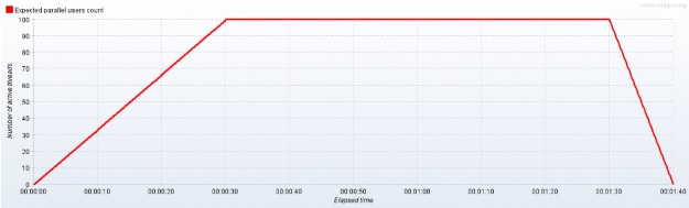
Since WordPress runs using PHP, MariaDB (MySQL) and Nginx (Apache), we installed WordPress at each system to create natural test conditions. JMeter tests were run accessing WordPress's default main page
We noticed that the response failed if more than 140 parallel users accessed the simple WordPress-based web-page)
TPS is abbreviation for Transaction Per Second, so this is the closest test to the user's environment.
As you can see the table above, a HDD is slightly more faster than a MicroSD card for random access speed. The result of OLTP TPS and sequence access speed are quite good, but random access speed is not acceptable. The average TPS shown above is just an average value, and you need to know that random access speed is one of the most important value for the overall system speed. The OLTP results of the HDD ODROID varied a lot between tests. However, for sequence access speed, it is almost as fast as a desktop. So, using an HDD in the ODROID-HC1 for a NAS can be a good choice.
In the 100 parallel users TPS test, there is not much of a difference among them. However, in the other tests such as, the OLTP TPS and IOzone test, the SSD or eMMC 64G seems faster than the others. In the file IO test, the SSD is the fastest at per-request statistics result.
Based on above results, it is not recommended that an HDD or MicroSD card be used with a LEMP or LAMP stack. We recommend that you use an eMMC or SSD for the best performance with an ODROID-XU4/HC1/HC2 when you are hosting a website and/or using it as a NAS. For additional details, please visit the original article at http://bit.ly/2l5aUs1.
Linux Kernel 4.14: ODROID-XU3/4/MC1/HC1 Support
November 1, 2017By Marian MihailescuLinux
Exynos 5422 is a Samsung System-on-a-chip (SoC) that has been at the core of Hardkernel’s products for several years. Starting with the high-end ODROID-XU3, it has been released later in a more affordable variant, the ODROID-XU3 Lite, went through a completely redesign in the ODROID-XU4 and XU4Q, and recently found itself at the core of the new ODROID-HC1 and MC1, geared towards NAS usage and clusters, respectively. Initially released with Linux kernel version 3.10, there has been many tries to update the Exynos 5422-based ODROID products to a more recent Linux kernel, with experimental kernels released for versions 4.0, 4.2, 4.4, and 4.8 by the community, until Hardkernel helped developed and released a stable kernel version 4.9.
During each Linux kernel development cycle, the SoC gained more updates in the mainline kernel due to the efforts of Samsung and the community. Thus, it is getting easier to get updated to the latest version of the kernel. In fact, for a while, Exynos 5422-based ODROIDs can use the mainline kernel without modifications. The issue however is that mainline version does not have all the drivers included and some systems won’t work. The next Linux kernel with Long Time Support (LTS) is version 4.14, due to be released in November. Coincidentally, it was recently revealed that LTS kernel support is being extended to 6 years. This means that version 4.14 will get support until the end of 2022. This is great news for the owners of small, extensible, powerful and inexpensive boards such as the ODROIDs.
This kernel version becomes particularly attractive for the Exynos 5422 ODROIDs, especially since it includes important fixes for the hardware video decoder and encoder (MFC), the hardware scaler and color space converter (GScaler), and a brand new driver for the HDMI CEC, that exposes the device as a infrared remote control. In addition, there are a myriad of fixes from the version 4.9 maintained by Hardkernel that can benefit ODROID users, such as improvements to the EXT4 and BTRFS filesystems, improvements to the kernel-based virtual machine (KVM), new and updated WiFi drivers, and improvements to the media drivers (for e.g. better TV tuners support).
The community stepped in and started fixing the remaining issues even before the 4.14 kernel is released:
Mali drivers were updated to version r20p0
Support was added for the Heterogeneous Multi-Processing (HMP) CPU scheduler
Fixes for the USB3 ports in the ODROID
Fix for the Gigabit Ethernet interface
Added support for interfaces such as the power button, SPI, ADC, GPIOs
HDMI Sound driver for the ODROID-XU4
Improvements for the emmc/sd card including support for higher speeds
Improved support for the virtual machine hypervisor
Enabled support for the hardware watchdog
Added support for the CPU hardware performance counters (PMU)
Included the official support for ODROID-HC1 (scheduled for the kernel version 4.15)
Added support for extra CPU frequencies, and improved thermal characteristics
Added support for Samsung CPU ASV tables to improve CPU voltage selection and thermals
With most fixes and patches developed or imported from kernel 4.9, kernel version 4.14 is already ready for public testing. Those interested can download, compile, and install the kernel on the official Hardkernel Ubuntu distribution using these instructions:
$ git clone --depth 1 --single-branch -b odroidxu4-4.14.y https://github.com/mihailescu2m/linux
$ cd linux
$ wget https://gist.github.com/mihailescu2m/115c9e2135f9b12f3d05669e18137c3d -O .config
$ make -j 8 zImage dtbs modules
$ sudo cp arch/arm/boot/zImage arch/arm/boot/dts/*.dtb /media/boot
$ sudo cp .config /media/boot/config
$ sudo make modules_install
$ kver=`make kernelrelease`
$ sudo cp .config /boot/config-${kver}
$ cd /boot
$ sudo update-initramfs -c -k ${kver}
$ sudo mkimage -A arm -O linux -T ramdisk -a 0x0 -e 0x0 -n initrd.img-${kver} -d initrd.img-${kver} uInitrd-${kver}
$ sudo cp uInitrd-${kver} /media/boot/uInitrd
Feedback and testing results are welcomed on the "Kernel 4.14 debugging party" forum thread at http://bit.ly/2ltTPbD.
ODROID-C2: Power Off and Wake Up Using a Simple GPIO Button
November 1, 2017By Justin LeeODROID-C2, Tinkering
This article describes how to setup a GPIO key button for power off and wake up purposes. The brief setup steps include the following:
Connecting a tab button to the pin port you want to use
Setting the GPIO number using boot.iniCompiling and flashing the modified kernel
DTS, which is only needed for Android
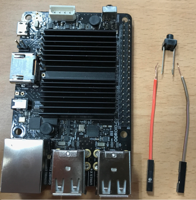
Hardware Setup
First, you need to prepare a tab switch that will be connected to two GPIO lines. The red wire will be for power and the gray wire will be for the active level line (ground or 3.3V power).
Figure 1 - Material for ODROID-C2 Power Button project
The ODROID-C2 pin layout diagram at http://bit.ly/2aXAlmt will come in very handy for this project. In our case, we will use Pin# 29 of the 40-pin expansion connector. The pin is assigned to GPIOX.BIT0 and its GPIO number is 228. Connect the red line to Pin# 29. Its default pin pulled status is high and switch active will be low. So, you should connect the gray line of tab switch to Ground (GND), Pin# 30.
Pin Number(Red Line)
GPIO Number
Active Level(Gray Line)
29
GPIO# 228
Active Low (Pin 30)
Available Keys
Here are the available key examples on the 40-pin connector and 7-pin connector. You can find the pin assign examples for Red Line and Gray Line.
(1) J2 - 2×20 pins
Active Level(Gray Line)
GPIO #
Pin #(Red Line)
Pin #(Red Line)
GPIO #
Active Level(Gray Line)
-
3.3V Power
1
2
-
-
-
-
3
4
-
-
-
-
5
6
Ground
-
Active Low (Pin 9)
GPIO# 249
7
8
-
-
-
Ground
9
10
-
-
Active Low (Pin 14)
GPIO# 247
11
12
GPIO#238
Active Low (Pin 14)
Active Low (Pin 14)
GPIO# 239
13
14
Ground
-
Active Low (Pin 14)
GPIO# 237
15
16
GPIO#236
Active Low (Pin 14)
-
3.3V Power
17
18
GPIO#233
Active Low (Pin 20)
Active Low (Pin 20)
GPIO# 235
19
20
Ground
-
Active Low (Pin 20)
GPIO# 232
21
22
GPIO#231
Active Low (Pin 20)
Active Low (Pin 25)
GPIO# 230
23
24
GPIO#229
Active Low (Pin 25)
-
Ground
25
26
GPIO# 225
Active High (Pin 17)
-
-
27
28
-
-
Active Low (Pin 30)
GPIO# 228
29
30
Ground
-
Active Low (Pin 30)
GPIO# 219
31
32
GPIO# 224
Active Low (Pin 34)
Active High (Pin 17)
GPIO# 234
33
34
Ground
Active Low (Pin 34)
GPIO# 214
35
36
GPIO# 218
Active Low (Pin 34)
-
-
37
38
-
-
-
Ground
39
40
-
-
(2) J7 - 1×7 pins
Pin #(Red Line)
GPIO #
Active Level(Gray Line)
1
Ground
-
2
GPIO# 128
Active Low (Pin 1)
3
5.0V Power
-
4
GPIO# 130
Active Low (Pin 1)
5
GPIO# 132
Active Low (Pin 1)
6
GPIO# 131
Active Low (Pin 1)
7
GPIO# 133
Active Low (Pin 1)
You can find the detailed information about 40-pin and 7-pin expansion connectors at http://bit.ly/2gzCA7c.
Ubuntu software setup
The release version should be 3.14.79-107 (Feb 26, 2017) or higher. You can assign GPIO number with env gpiopower in boot.ini:
If you intend to turn the board off using the power button, you will need to change the power key action pattern. To facilitate that, first open the Power Management Preferences dialog ([System] → [Preferences] → [Hardware] → [Power Management]) and select the [General] tab.
Figure 2: Power management preferences
Wake up Action
To wake the system up after power off, a long-duration (2-3 seconds) pressing of the power button is needed.
Android software setup
In Android, you have to modify the DTS file in Android Marshmallow (v2.4) and higher version to use this functionality.
You will have to modify the DTS file to activate the GPIO key functionality:
/arch/arm64/boot/dts/meson64_odroidc2.dts
...
gpio_keypad{
    .
    status = "okay";
    .
};
…
After compiling the DTS file, you can flash the DTB file to the board:
$ make odroidc2_defconfig
$ make dtbs
$ fastboot flash dtb arch/arm64/boot/dts/meson64_odroidc2.dtb
$ fastboot reboot
You have to flash the DTBS file when the board is in u-boot fastboot mode:
$ reboot fastboot
Setting boot.ini
In the Android boot.ini, you can uncomment the “gpipower” entry and modify the number to the number relevant in your case:
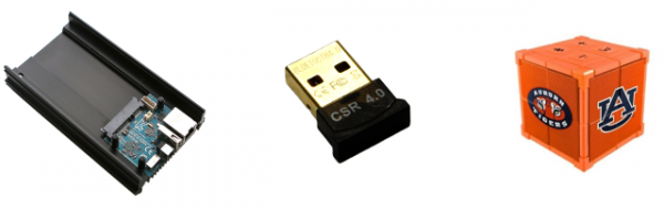
MicroSD Card for OS, 8GB Class 10 or higher version is required
LAN cable
Figure 1 - Hardware requirements for the Google Assistant project
Insert the Bluetooth dongle into the USB port of the ODROID-HC1, then turn on the ODROID-HC1 and Bluetooth speaker to begin.
Sound settings
To access the ODROID-HC1 console, get the IP address of the board as described at http://bit.ly/2yXFLwp. This guide is based on the latest Ubuntu 16.04 minimal OS. To get the OS image, download it from http://bit.ly/2yXYs3h. Before starting the system settings, add the new user account ODROID as a sudo user, because Ubuntu minimal does not have any user accounts:
Add the pulseaudio permission to the user account. Add the “load-module module-switch-on-connect” line to the pulseaudio configuration file. This setting changes the audio output to the Bluetooth speaker automatically:
Enter the following commands on the bluetoothctl console. Note that the MAC address of the Bluetooth speaker should be changed from 00:11:67:AE:25:C6 to your own MAC address. This address will be different for each Bluetooth device, so be sure to replace the address by adding yours:
[bluetooth]# agent on
[bluetooth]# default-agent
[bluetooth]# scan on
[bluetooth]# pair 00:11:67:AE:25:C6
[bluetooth]# trust 00:11:67:AE:25:C6
[bluetooth]# connect 00:11:67:AE:25:C6
[bluetooth]# quit
The Bluetooth speaker must have a set default. In order to set the A2DP (Advanced Audio Distribution Profile) as the default, change the profile to HSP (Head Set Profile) because A2DP cannot use the microphone.
$ pacmd ls
Check the card index of the Bluetooth speaker, and assume the index is 1:
$ pacmd set-card-profile 1 headset_head_unit
To verify sound and Bluetooth setup was done correctly, play a test sound:
$ speaker-test -t wav
Record and playback some audio using the ALSA command-line tools:
In order to enable the Google Assistant API, refer to the Google Assistant SDK Guides page at http://bit.ly/2pXwqfC. Use a Google account to sign in. If a Google account has yet to be produced, create one. Trying the Google Assistant API is free for personal use.
Configure a Google Developer Project
A Google Developer Project allows any ODROID device access to the Google Assistant API. The project tracks quota usage and gives valuable metrics for the requests made from ODROID devices on the network.
To enable access to the Google Assistant API, first go to the Projects page in the Cloud Platform Console at and select an existing project or create a new project. Go to the Projects page at http://bit.ly/2gY7pSV. Next, enable the Google Assistant API on the project you selected and click Enable. More information about enabling the API is available at http://bit.ly/2A1ewic.
Next, create an OAuth Client ID by first creating the client ID, as described at http://bit.ly/2xBjII6. You may need to set a product name for the product consent screen. On the OAuth consent screen tab, give the product a name and click Save, then click Other and give the client ID a name, and click Create. A dialog box appears that shows you a client ID and secret. There’s no need to remember or save this, just close the dialog. Next, click at the far right of screen for the client ID to download the client secret JSON file (client_secret_.json). The client_secret_.json file must be located on the device to authorize the Google Assistant SDK sample to make Google Assistant queries, and should not be renamed. Finally, copy client_secret_.json to the ODROID-HC1:
In order to use the Google Assistant, certain activity data must be shared with Google. The Google Assistant needs this data to function properly, and it is not specific to the SDK. To do this, open the Activity Controls page for the Google account to be used with the Assistant at http://bit.ly/2ig4QIB. Any Google account has this option, and it does not need to be your developer account. Ensure the following toggle switches are enabled (blue):
Web & App Activity
Device Information
Voice & Audio Activity
Download and run the Google Assistant API sample
Use a Python virtual environment to isolate the SDK and its dependencies from the system Python packages:
If you face the locale problem as shown below, set the LC_ALL environment variable:
Complete output from command /home/odroid/env/bin/python2 - setuptools pkg_resources pip wheel:
Traceback (most recent call last):
File "", line 24, in
File "/usr/share/python-wheels/pip-8.1.1-py2.py3-none-any.whl/pip/__init__.py", line 215, in main
File "/home/odroid/env/lib/python2.7/locale.py", line 581, in setlocale
return _setlocale(category, locale)
locale.Error: unsupported locale setting
$ export LC_ALL=C
$ virtualenv env --no-site-packages
Activate Python virtual environment.
$ env/bin/python -m pip install --upgrade pip setuptools
$ source env/bin/activate
After activating the Python virtual environment, the “(env)” string is added in front of the prompt.
Authorize the Google Assistant SDK sample to make Google Assistant queries for the given Google Account. Reference the JSON file that was copied over to the device in a previous step and install the authorization tool:
Copy the URL and paste it into a browser. This can be done on a development machine, or any other machine. After it is approved, a code will appear in the browser, such as “4/XXXX”. Copy and paste this code into the terminal:
Enter the authorization code:
If authorization was successful, OAuth credentials will be initialized in the terminal. If InvalidGrantError shows instead, then an invalid code was entered. If this occurs, try again, taking care to copy and paste the entire code. If the correct authorization code is entered, then the credentials.json file is generated:
Run and test the pushtotalk sample. If the sample program is working well, this work is almost done:
(env) $ python pushtotalk.py
INFO:root:Connecting to embeddedassistant.googleapis.com

Press Enter to send a new request...
Copy the sample to the working directory. Deactivate the Python virtual environment. There are additional steps to take to produce a useful AI speaker. In order to that, navigate to the $(HOME)/ai_speaker directory:
(env) $ cd ..
(env) $ cp -r grpc ~/ai_speaker
(env) $ cd ~/ai_speaker
(env) $ cp pushtotalk.py ai_speaker.py
(env) $ deactivate
$ cd
Wake-Up-Word
The push-to-talk sample looks like it will interact with the AI assistant. However, before communicating with the AI assistant, press the enter key first. To detect a Wake-Up-Word like “Okay, Google”, “Alexa” or “Jarvis”, use CMUSphinx at https://cmusphinx.github.io , which is the open source local speech recognition toolkit. It is best to build and install SphinxBase, because SphinxBase provides common functionality across all CMUSphinx projects:
$ sudo apt install libtool bison swig python-dev autoconf libtool automake
$ git clone --depth 1 https://github.com/cmusphinx/sphinxbase.git
$ cd sphinxbase
$ ./autogen.sh
$ make -j8
$ sudo make install
$ cd
Sphinxbase will be installed in the “/usr/local/” directory by default. Not all systems load libraries from this folder automatically. In order to load them, configure the path to look for shared libraries. This can be done either in the “/etc/ld.so.conf” file, or by exporting the environment variables:
Build and install PocketSphinx. PocketSphinx is a lightweight speech recognition engine specifically tuned for handheld and mobile devices, although it works equally well on the desktop:
$ git clone --depth 1 https://github.com/cmusphinx/pocketsphinx.git
$ cd pocketsphinx
$ make -j8
$ sudo make install
$ cd
To test the installation, run pocketsphinx_continuous and check that it recognizes words you speak into your microphone:
$ pocketsphinx_continuous -inmic yes
For more information about building PocketSphinx, please refer to the “Building an application with PocketSphinx” page at http://bit.ly/2gZhHT5.
Add the pocketsphinx_continuous program as a subprocess in the AI speaker program. The program pocketsphinx_continuous is a good tool for detecting hotwords because it recognizes speech asynchronously. Remove the wait_for_user_trigger related lines, because the hotwords are the trigger:
$(HOME)/ai_speaker/ai_speaker.py

 """Sample that implements gRPC client for Google Assistant API."""

# Add subprocess module
 import subprocess
 import json
 import logging
 import os.path

(......)

# Add below's routines in the 'While True:' loop
 while True:
 p = subprocess.Popen(args = ['pocketsphinx_continuous','-inmic', 'yes', '-kws_threshold', '1e-16', '-keyphrase', 'hey dude'],
 stdin = subprocess.PIPE,
 stdout = subprocess.PIPE,
 universal_newlines=True)
 while p.poll() is None:
 data = p.stdout.readline()
 if data.find("hey dude") is not -1:
 print "Detected Hotwords"
 p.stdout.flush()
 break
 p.terminate()
The Wake-Up-Word is “hey dude”. Run the program, say “hey dude,” and then state anything desired to the AI assistant:
(env) $ cd ai_speaker
(env) $ python ai_speaker.py
Detection sound
There is a problem after initially adding Wake-Up-Words, because there is no apparatus in place to detect whether the AI speaker detects hotwords or not. The timing must be known in order to command the AI assistant by voice. This can be fixed by adding the detection sound to the program. Download the sample detection sound at http://bit.ly/2zkSV3b, then copy the detect.wav file to the ODROID-HC1:
$ scp ~/Downloads/detect.wav odroid@:~/
Use the pyaudio and wave module in order to play the .wav file in the Python source code:
(env) $ pip install --upgrade pyaudio wave
Add the detection sound play routine to the program. Full differences including the Wake-Up-Words routines are the following:
(env) $ nano ai_speaker.py
diff file between original sample code pushtotalk.py and modified program ai_speaker.py
 --- pushtotalk.py 2017-10-19 15:42:12.164741800 +0000
 +++ ai_speaker.py 2017-10-19 15:41:49.644811151 +0000
 @@ -14,6 +14,9 @@

"""Sample that implements gRPC client for Google Assistant API."""

+import pyaudio
+import wave
+import subprocess
import json
import logging
import os.path
@@ -310,14 +313,38 @@
# keep recording voice requests using the microphone
# and playing back assistant response using the speaker.
# When the once flag is set, don't wait for a trigger. Otherwise, wait.
- wait_for_user_trigger = not once
+ chunk = 1024
+ pa = pyaudio.PyAudio()
+ while True:
- if wait_for_user_trigger:
- click.pause(info='Press Enter to send a new request...')
+ p = subprocess.Popen(args = ['pocketsphinx_continuous','-inmic', 'yes', '-kws_threshold', '1e-16', '-keyphrase', 'hey dude'],
+ stdin = subprocess.PIPE,
+ stdout = subprocess.PIPE,
+ universal_newlines=True)
+ while p.poll() is None:
+ data = p.stdout.readline()
+ if data.find("hey dude") is not -1:
+ print "Detected Hotwords"
+ p.stdout.flush()
+ break
+ p.terminate()
+
+ # Play the detection sound
+ f = wave.open(r"/home/odroid/detect.wav","rb")
+ stream = pa.open(format = pa.get_format_from_width(f.getsampwidth()),
+ channels = f.getnchannels(),
+ rate = f.getframerate(),
+ output = True)
+ wav_data = f.readframes(chunk)
+
+ while wav_data:
+ stream.write(wav_data)
+ wav_data = f.readframes(chunk)
+ stream.stop_stream()
+ stream.close()
+ f.close()
+
continue_conversation = assistant.converse()
- # wait for user trigger if there is no follow-up turn in
- # the conversation.
- wait_for_user_trigger = not continue_conversation

# If we only want one conversation, break.
if once and (not continue_conversation):
# Run the AI speaker program.
(env) $ python ai_speaker.py
The detection rate of the Wake-Up-Words is less than ideal. Whether using pocketsphinx or another solution, the Wake-Up-Words routine needs improvement, so adding custom commands is useful for this particular project. For example, it is easy to control IoT devices by voice by using the Google Assistant SDK. Different solutions can be found by entering the search query “action on google” to learn more about extending the Google Assistant.
To save time, an easy custom command solution can be used by simply adding the custom command to the ai_speaker.py program. In the pushtotalk sample, find the request text which is already recognized by voice:
--- pushtotalk.py 2017-10-19 16:07:46.753689882 +0000
+++ pushtotalk_new.py 2017-10-19 16:09:58.165799271 +0000
@@ -119,6 +119,15 @@
logging.info('Transcript of user request: "%s".',
resp.result.spoken_request_text)
logging.info('Playing assistant response.')
+ #Add your custom voice commands here
+ #Ex>
+ #import os
+ #r_text = resp.resut.spoken_request_text
+ #if r_text.find("play music") is not -1:
+ # os.system("mplayer ~/Music/*&")
+ #if r_text.find("turn on light") is not -1:
+ # os.system("echo 1 > /sys/class/gpio/gpio1/value")
+
if len(resp.audio_out.audio_data) > 0:
self.conversation_stream.write(resp.audio_out.audio_data)
if resp.result.spoken_response_text:
After this modification has been saved, you can begin experimenting with controlling the home electronic devices using the IOT controller with voice commands. For comments, questions, and suggestions, please visit the original article at http://bit.ly/2iQ629K.
Exploring Software-Defined Storage with GlusterFS on the ODROID-HC1: Part 1 - Server Setup
November 1, 2017By Andy YuenODROID-HC1
“Software-defined storage (SDS) is a computer program that manages data storage resources and functionality and has no dependencies on the underlying physical storage hardware.” - whatis.com.
"Gluster File System (GlusterFS) is an SDS platform designed to handle the requirements of traditional file storage: high-capacity tasks like backup and archival, as well as high-performance tasks of analytics and virtualization." - Red Hat.
While GlusterFS is clearly an enterprise technology, that does not mean that it cannot be used at home. To the contrary, I find it more flexible and scalable than those off-the-shelf Network Attached Storage (NAS) boxes. NAS servers for home users usually come in 2 or 4 bays. When the time comes to expand your system, it is not that flexible. You either need to change to a bigger box with more bays, or replace all of your disks with higher capacity ones. GlusterFS scales horizontally, meaning that you can add more servers to expand your storage capacity. For home users, adding more servers does not make any sense, since servers are quite expensive. This is true until you consider the ODROID-HC1, which retails for only $49 USD. Four ODROID-HC1s can be equated to a single 4-bay NAS at roughly 50% of the price. Furthermore, the ODROID-XU4 processor, consisting of four A15 cores and four A7 cores on each HC1, is already more powerful than the average NAS targeting the home market, which usually comes with a dual-core A15 processor.
In this article, I am going to use four ODROID-HC1s to create a highly scalable and highly available distributed replicated GlusterFS volume, similar to a RAID 1+0 configuration. Don’t worry if you only have two HC1s on hand. I will describe how you can create a replicated GlusterFS volume that is the equivalent of RAID 1. But before that, let’s explore a bit more on the different GlusterFS volume types.
GlusterFS Volume Types
GlusterFS is a POSIX-compatible distributed file system. It uses the Elastic Hash Algorithm to intelligently hash to locations based on path and filename, instead of relying on a metadata server like some other distributed file systems. Consequently, it avoids the metadata performance bottleneck, and can run on heterogeneous commodity hardware.
A volume is a collection of bricks. A brick is any directory on an underlying disk file system. Most of the GlusterFS operations happen on the volume. GlusterFS supports different types of volumes which are optimised for scaling storage capacity, improving performance, or both. You may want to refer to Gluster Docs at http://bit.ly/2zhI51S for a complete rundown. In this article, I will explore two types, namely replicated volume and distributed replicated volume which require two and four servers (or HC1s), respectively. In my opinion, these are the configurations most suitable for home use.
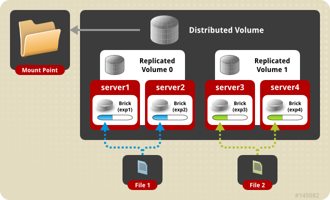
Replicated volume means that files are always written to the bricks of the two servers. This is equivalent to RAID 1. In a distributed replicated volume, files are written either to the brick on one server or the brick on another server, in a trusted pool of GlusterFS nodes. I will discuss trusted pools later. The bricks on the two servers are replicated to the other two servers in the pool. This is similar to RAID 1+0 but with one major difference: RAID 1+0 uses striping, meaning that different blocks of a file are written to different servers. In distribution, a file is either completely written to one server or another and the contents on the two servers are replicated to another two servers as illustrated in the diagram below.
Figure 1 - Distributed Replicated
Using a distributed replicated volume guards against data loss when one server fails. It also enhances performance when you are concurrently accessing files which have been distributed to two separate servers. Instead of having one server serving up the files, two are serving up the files. Now that we’ve discussed the theory, let’s get our hands dirty building these volumes.
Building a distributed replicated GlusterFS volume
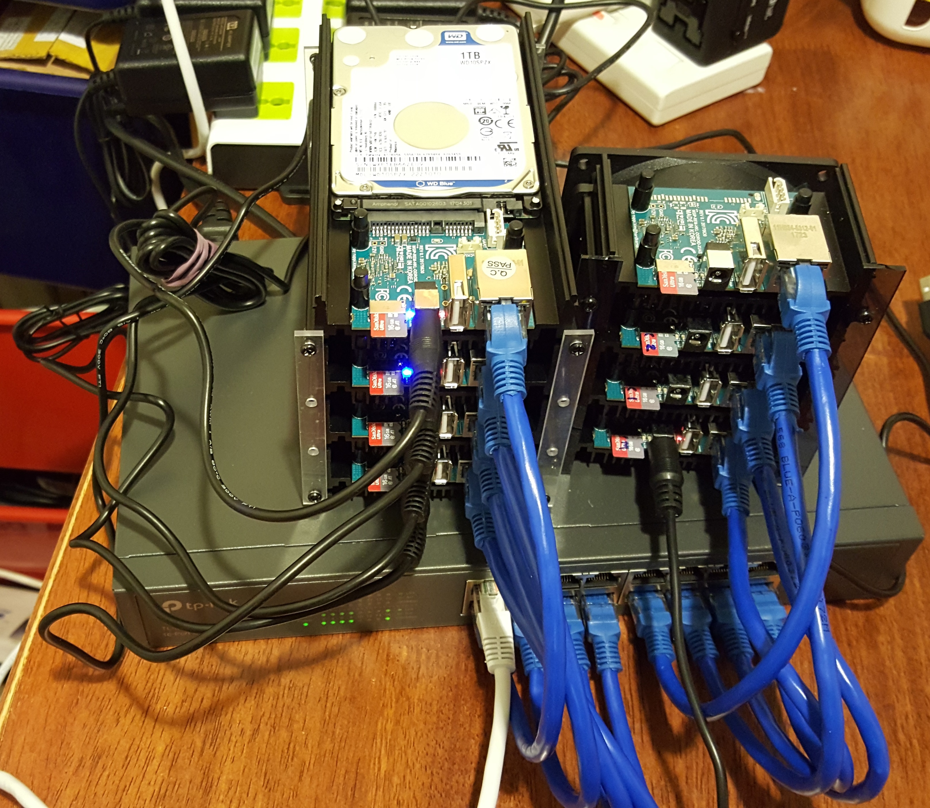
Figure 2 shows a photo of my setup. On the left are the four stacked ODROID-HC1s, and on the right is the ODROID-MC1 cluster. Both are resting on and connected to a 16-port Gigabit switch.
Figure 2 - Lab Environment
Setting up the ODROID-HC1s
You’ll need to copy the OS image to your SD card in order to boot up your HC1s. Then, set a static IP address and a unique hostname to each HC1. You may want to follow the instructions under "Setting Up the OS on Each Computer on the Cluster" in my MC1 article at http://bit.ly/2lrzVhb. Change the host names to xu4-gluster0, xu-4-gluster1, xu-4-gluster2, and so on.
Install and Format the Hard Disk
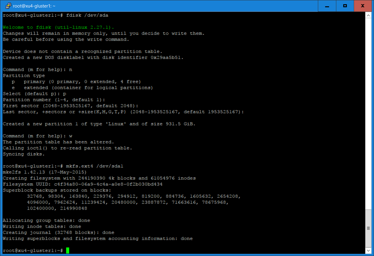
Insert the hard disks into the SATA connectors of your HC1s. Type “sudo -as” to access root privileges and create a Linux partition using fdisk, then create an ext4 file system, as shown in Figure 3.
Figure 3 - fdisk
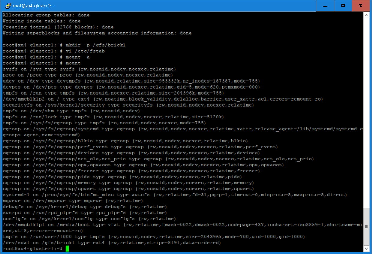
Create a directory called /gds/brick1, add an entry to /etc/fstab, and mount the file system. The result is shown in Figure 4.
Add the following line to your /etc/fstab (without the quotation marks): “/dev/sda1 /gfs/brick1 ext4 defaults 0 1”, then type the following commands:
$ mount -a
 $ mount
Install and configure Gluster server and volume
Install the GlusterFS server
Create a trusted pool of GlusterFS nodes. A storage pool is a trusted network of storage servers. Before one can configure a GlusterFS volume, one must create a trusted (storage) pool consisting of the storage servers that provide bricks to a volume.
Create a directory for volume
Create a distributed replicated volume named gvolume0
Start the volume and display its status
The commands used are summarised below (run as root):
Execute on all HC1 servers the following commands:
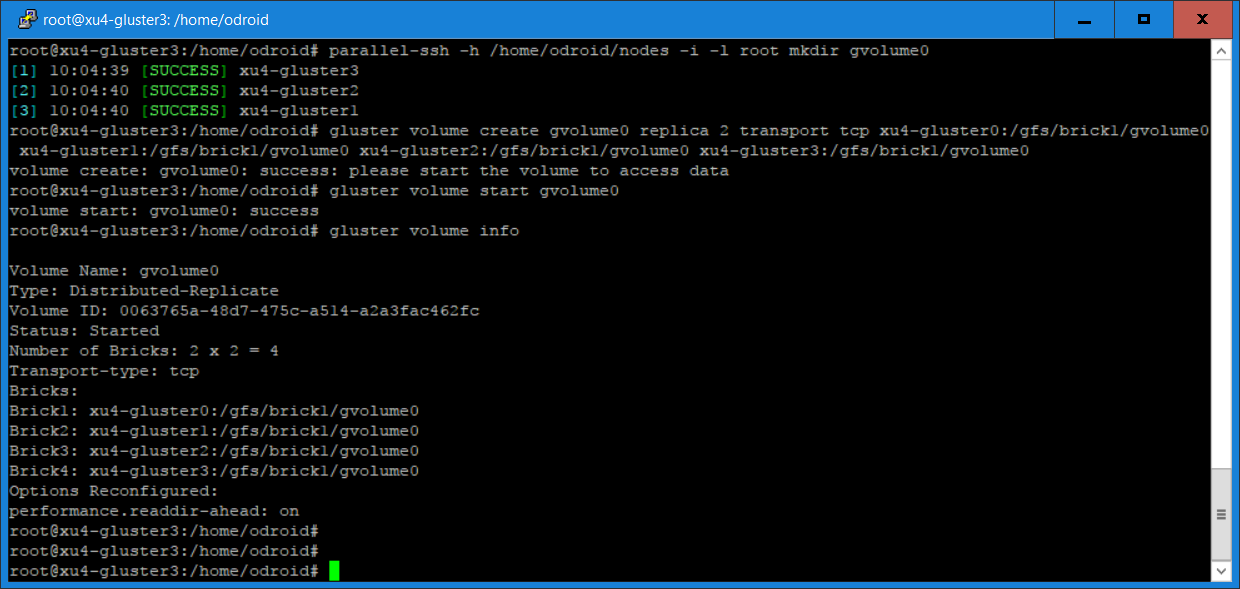
In a distributed replicated volume, files are distributed across replicated sets of bricks. The number of bricks must be a multiple of the replica count, which in our case is two. The order in which the bricks are specified is important. In the “gluster volume create” command, adjacent bricks become replicas of each other. This type of volume provides high availability via replication and scaling via distribution. In our command, we use four bricks and replica count two, resulting in the first two bricks becoming replicas of each other. This volume is denoted as 2 x 2. Figure 5 shows the output of some of the commands.
Figure 5 - Create Volume
For those who only have two HC1s to create a replicated volume, you only have to use the command "gluster peer probe" on the other server and replace the "gluster volume create" command with the following command:
Note that if you want the mount to be permanent, you have to add an entry in the /etc/fstab file.
A simple test
This a simple test showing the distribution of files on a distributed replicated GlusterFS volume.
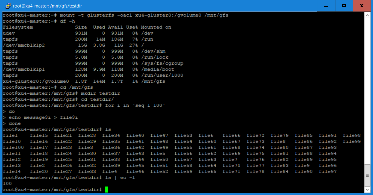
Create 100 files using the command:
$ cd /mnt/gfs
 $ mkdir testdir
 $ cd testdir
 $ for i in `seq 1 100`
 $ do
 $ echo message$i > file$i
 $ done
 $ ls
The output of these commands are shown in Figure 6.
Figure 6 - Client Files
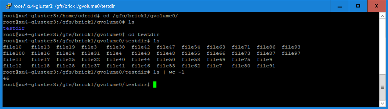
Login to xu4-gluster0 and issue the following commands:
$ cd /gfs/brick1/gvolume0/testdir
 $ ls
 $ ls | wc -l
You will notice in Figure 7 that 46 of the 100 files are saved on this server, since we are using a distributed replicated volume.
Figure 7 - Gluster0 Files
Login to xu4-gluster1 and issue the same commands:
$ cd /gfs/brick1/gvolume0/testdir
 $ ls
 $ ls | wc -l
You will see from the screenshot that there are 54 files on this server. The total on both servers adds up to the 100 files that we created earlier. For our distributed replicated volume, the 100 files are distributed between the two servers, although not exactly in a 50/50 ratio. You will find the same result if you log into the other two servers (xu4-gluster2 and xu4-gluster3). For those of you who created a replicated volume using two ODROID-HC1s, you will see the 100 files on both servers as yours is a replicated volume and not distribution volume.
What Next?
I have described how to build distributed replicated and replicated GlusterFS volumes using four and two ODROID-HC1s respectively. I have also shown how to access the GlusterFS volume using a GlusterFS client. In Part 2 of this article, I will describe how to install and use other clients including NFS and Samba (for Windows) to access the GlusterFS volume and compare the performance of these clients.
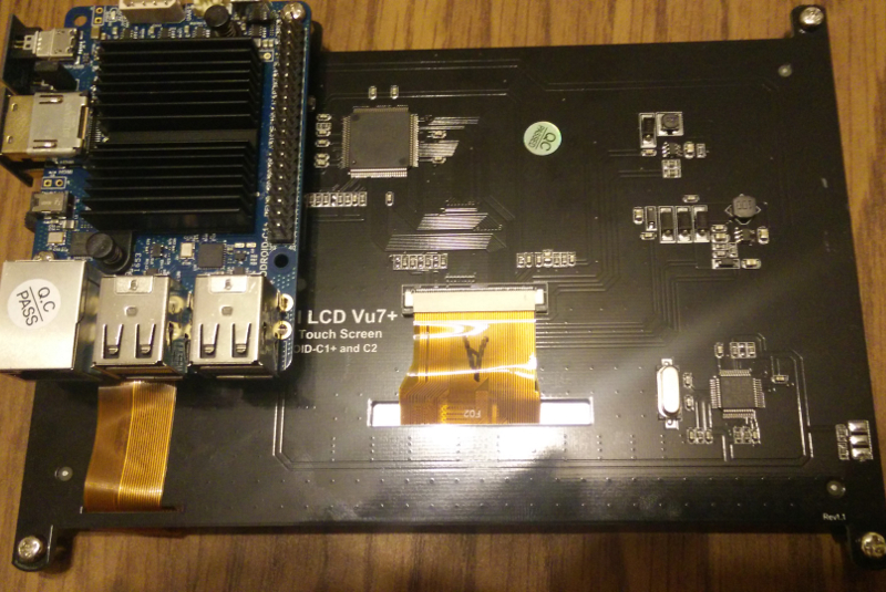
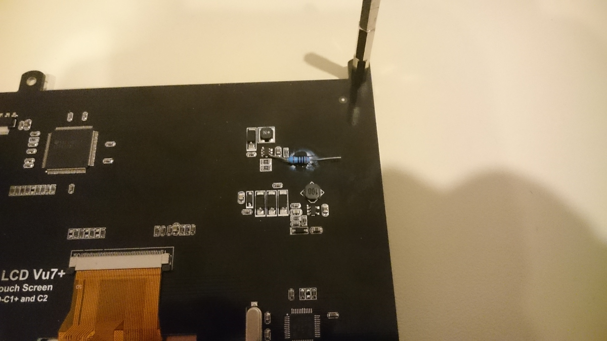
ODROID-VU7+ Backlight Control Hack: Controlling the Backlight on the ODROID-C1 and ODROID-C2 Android platforms
November 1, 2017By Jörg WolffODROID-C1+, ODROID-C2, Tinkering
Recently, I made a driver to control the backlight for the ODROID-C1 and ODROID-C2 using PWM (pin 33). To use the driver, it needs to be copied to the folder system/lib/hw/. After rebooting, the driver should work properly.
The driver loads the kernel modules for PWM automatically, so pwm-meson.ko and pwm-ctrl.ko must be present, as they are normally. Keep in mind that if you use this driver, you’ll only be able to use the PWM as well as pin 33 for the backlight. The driver is available for download at http://bit.ly/2ysMPAS.
To copy the driver to the ODROID-C1, type the following command from a host machine running Android Debug Bridge (ADB) connected to the ODROID-C1 via a USB cable:
$ adb push lights.odroidc.so /system/lib/hw/
To support the ODROID-VU8, the boot argument “backlight_pwm=yes|no|invert” must be added to the boot.ini:
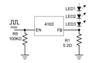
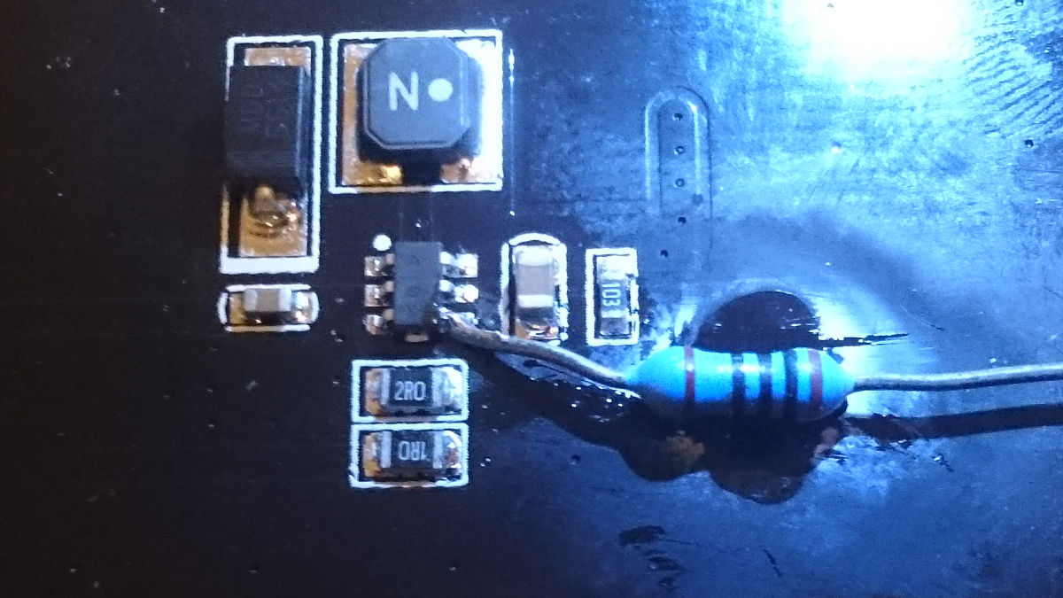
To control the backlight of the VU7+ you’ll need to do a little tinkering. On pin 4 of the PT4103 backlight driver, you’ll need to solder a resistor. I used a 330 Ohm resistor. It should, however, also be possible without a resistor. Other than in this picture from the datasheet of the 4103, the EN pin of the 4103 on the VU7+ has a pull-up 10k resistor. Therefore, the backlight of the VU7 is always enabled. I measured the current with the EN pin connected to GND. It is about 0.5mA, which comes from the pull-up resistor: 5V divided by 10k. I took a resistor and glued it on the board, soldering it carefully to the pin 4. This can then be connected to pin 33 of the ODROID.
November 1, 2017By Laurent Caneiro (@tipoto)Meet an ODROIDian
Please tell us a little about yourself.
I’m 40 years old and was born in Bordeaux, France. I live now in Los Angeles in California, with my wonderful wife Nathalie and my young daughter Hanaé, who is four years old. I work for DreamWorks animation studios as an animator. I have been working in the animation industry since 2000. I have worked on movies like “How to Train Your Dragon 1 and 2”, “Puss in Boots”, “Kung Fu Panda 3”, “Trolls” and a few more. I’m currently working on “How to train your Dragon 3” which is due to be released in March 2019. Prior to DreamWorks, I worked for several animation studios in Luxembourg, France, Belgium and Spain), which allowed me to discover different countries along with building my experience.
Figure 1 - Laurent at his workstation at DreamWorks Animation
What is your educational background?
I was not very studious when I was younger, which placed me in a tricky situation at the end of middle school. I basically couldn’t choose my branch, and my only choice was between secretarial and accounting studies. I chose accounting, even though I didn’t even know what it was all about, but I studied 4 years of accounting anyway and eventually got my diploma. Fortunately, I never stopped drawing and painting during my spare time, and after my accounting studies, I decided to attempt the entrance examination of an animation school in Luxembourg (L.T.A.M.) and I passed it! That is when I fell in love with animation.
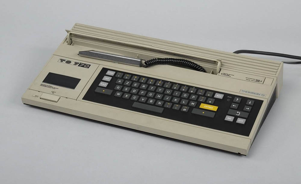
How did you get started with computers?
I started with computers when I was 8 or 9. At the time, I had a computer called Thompson TO7-70, which was released in France only I believe. I mainly played games with it, but my initiation in programming also started here. The computer used the BASIC language, and since my parents subscribed to a monthly BASIC magazine, I was able to learn a few things and start playing with the language.
Figure 2 - Laurent’s first computer, a Thompson T07-70
I’m not a programmer and my knowledge is pretty limited in this area, but I’m fascinated with it. I’m self-taught and I like to write useful little tools to make my day to day easier at work. I mainly use Shell script language, but I also use Python, Squirrel, C/C++ and other languages sometimes.
What attracted you to the ODROID platform?
I had a project in mind that I really wanted to realize. I first bought a Raspberry Pi 2, which is a great micro-controller, but it wasn’t powerful enough for my needs, so I investigated other boards as a replacement. I found the Hardkernel website and discovered the XU4. I was impressed by the specifications, but I also wanted to know if the community was big enough, so I went to the ODROID forums and did a lot of reading. After a few hours, my conclusion was that the forum was very active and the members were always available to help and were technically excellent. I decided to buy an XU4 and migrate my current project onto it.
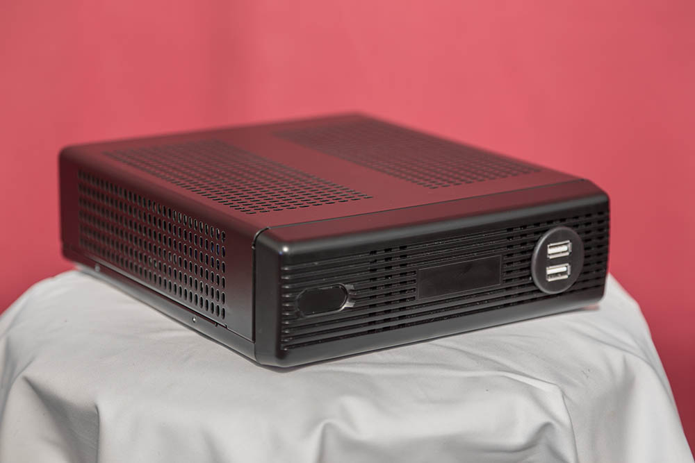
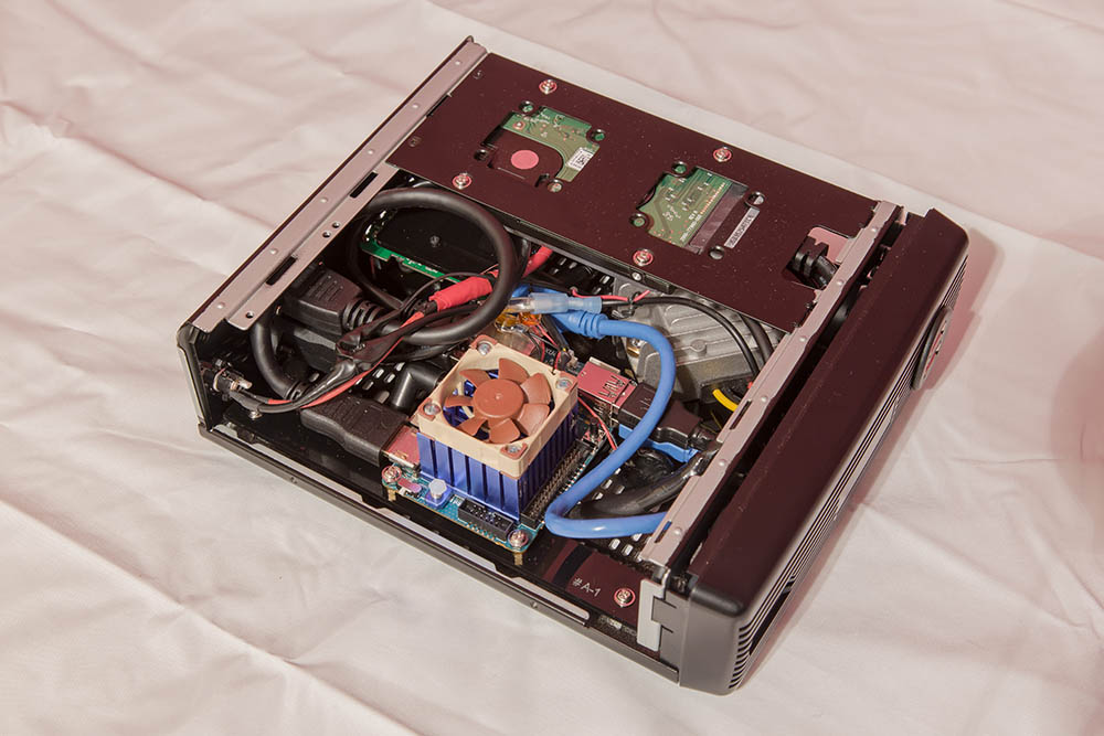
How do you use your ODROID?
I use my ODROID as a retro gaming console. I have been working on this project since 2015, because I’m very slow. My project is split in two pieces of hardware, one is the console itself and the other one is an arcade joystick for 2 players. For the console, I use a tiny PC case which I slightly modified, I designed an acrylic plate in which I attached all my components (XU4, USB hub, voltage regulator, HDD).
Figure 3 - Laurent has been building a custom gaming console since 2015
For the joysticks, I completely designed it from scratch, it’s also done with acrylic sheets. I use an Arduino combined with a RGB module board to control all the RGB leds inside the buttons. I use an IPAC2 to communicate between the button switches and the XU4. The hardware part is completely done and fully functional, I’m working now on the software side. I started with the OGST image from @meveric, but I’m customizing everything and I’m adding plenty of features to make it look unique and attractive.
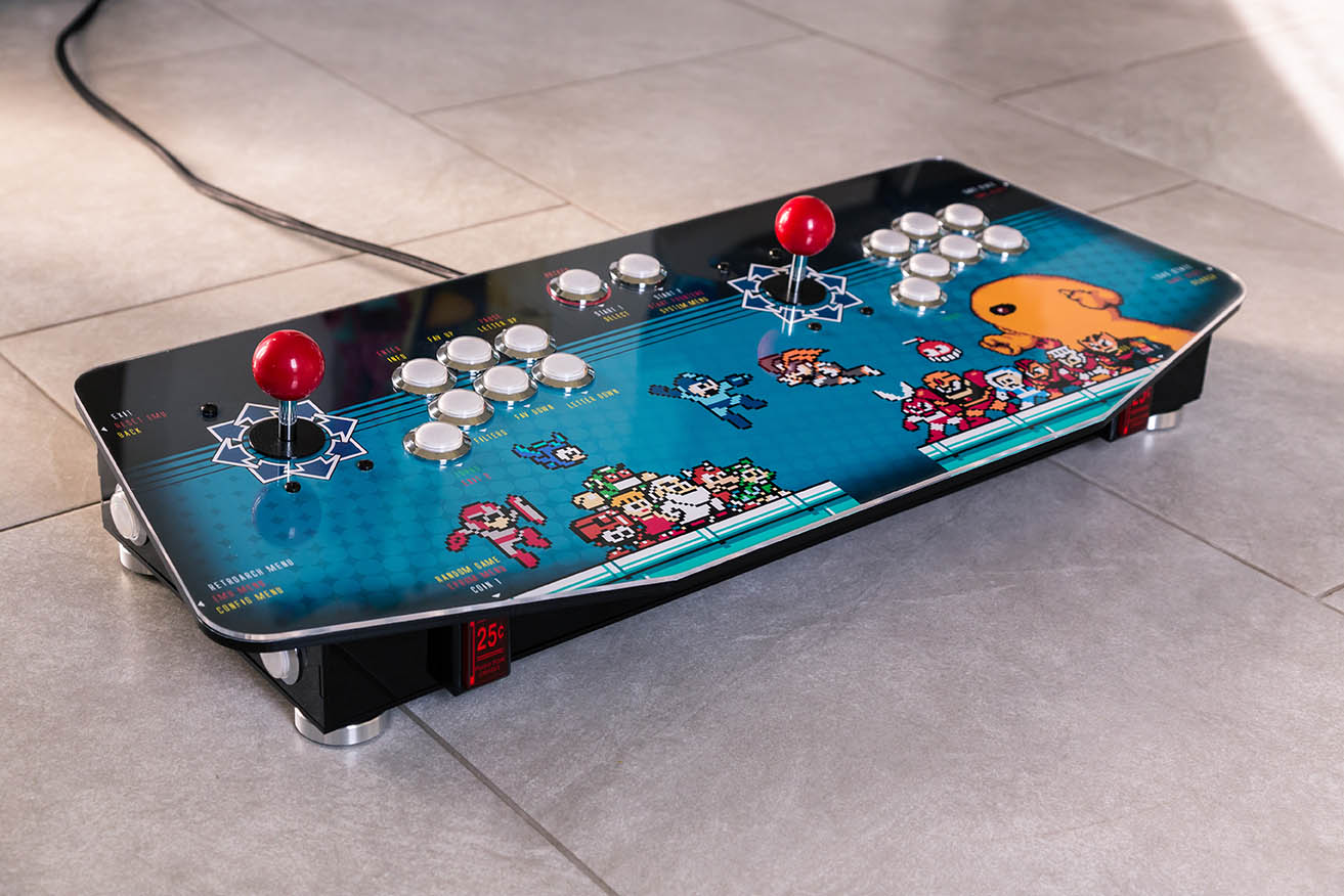
Figure 5 - The joysticks that Laurent designed for his gaming console are a work of art!
Which ODROID is your favorite and why?
It’s very hard for me to tell, since I only own the ODROID-XU4, but I really love this board.
What innovations would you like to see in future Hardkernel products?
I would like to see a board with an integrated Wifi module, an efficient cooling solution available for it that would avoid any throttle when the CPUs are working at a 100% load, and a great GPU support on Linux.
What hobbies and interests do you have apart from computers?
I enjoy photography, and play guitar and piano.
What advice do you have for someone wanting to learn more about programming?
Start with a friendly language with a great support on the Internet, so that you can always find solutions to your problems. Challenge yourself with fun little projects. Don’t try to go too big too fast, because you need to challenge yourself step-by-step so that you can learn and stay motivated at the same time. You don’t want to feel completely overwhelmed with something which is way too complicated for a beginning project. If you plan your progress slowly, you will always be ready to solve the next problem that you’ll be facing.
I personally do what I call a “blocking” before starting an “elaborate” code, which is to create a schematic view of what I want to do on paper, so that I have an overview of my entire code before starting it. I also recommend using the Internet as much as you can as an education resource.