

This article is about yet another homemade portable gaming console as a sequel to the first one that I built (http://bit.ly/2yFj4th). On the first build, I used an ODROID-W (pi clone) and a brand new GameBoy case. For this new project, I wanted something more powerful to run N64, Dreamcast and PSX games, but also some native Linux game. There are not a lot of low power consumption options with sufficient CPU+GPU for that, so I chose an ODROID-C0. Moreover, instead of using and transforming an existing case, I used a 3d printed one designed by myself with optimized dimensions and form factor. I want to thank the ODROID community (forum.ODROID.com), and in particular @meveric for his debian distribution and ODROID-optimized packages to make the GamODROID-C0.
Components
Here is a list of all components I used for this build:
Main parts:
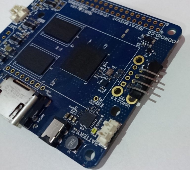
- ODROID-C0
- 8GB eMMC module
- 128 Gb MicroSD XC (SanDisk Ultra, XC I, class 10)
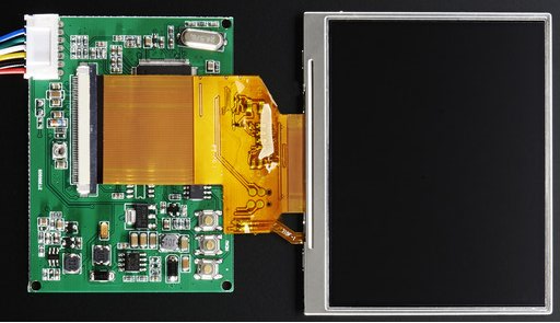
- 3.5″ NTSC/PAL TFT Display (http://bit.ly/2yUyXgd)
- A 4x6cm prototype PCB board
Audio Parts :
- Stereo 2.8W Class D audio amp
- 2 PSP 2000/3000 speakers
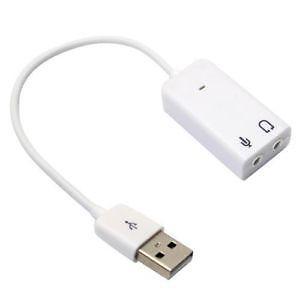
- A cheap USB sound card with a small USB cable
Battery Parts:
- 2 LiPo batteries : Keeppower 16650 3.7v 2500mA protected
- 2 MOLEX connectors, 50079-8100
- 2 MOLEX receptacle, 51021-0200
Control parts :
- 12 soft tactile 8mm muttons (http://bit.ly/2xN8qDW)
- 4 tactile button 6mm switches (http://bit.ly/2xNmlcU)
- 2 PSP 1000 analog sticks
- 1 Analog multiplexer MC14051BCL
Cooling parts :
- 2 PS3 GPU copper heatsink
- 4 15x15mm copper heatsink
- Some 1mm Thermal Pad
- Some Silicon Thermal paste
Various other electronic parts:
- A 3mm blue led
- Some wires from an old IDE ribbon cable
- Some breadboard connection wires
- 3 resistors
Decoration parts:
- Some Nail polish templates for colors (black, yellow, red, green, blue)
- 200, 600 and 1200 sandpaper
- XTC 3D (http://bit.ly/2fG3l5O)
- White satin spray paint
Anticipated power consumption
The main sources of power drain are the ODROID-C0, the display and the audio system (soundcard and audio amp). Before starting, I measured the consumption of these 3 components:
- ODROID-C0 : 200-400 mAh depending on CPU and GPU usage
- Audio system : 310 mAh
- Display : 420 mAh
It’s a total of 1130 mAh at 5v, so 5650 mAh / hour. The batteries I used are (at least) 3.7v x 5000 mA for a total of 18500 mA. The console should last more than 3h in all cases.
Why use a display with such poor resolution ?
There are several reasons for that: low power, 60 FPS, easy wiring, and it’s blurry like old TV which makes cool hardware anti-aliasing.
Why use cylindrical batteries?
It’s more a matter of space optimization regarding the capacity I wanted. Using a more classical flat battery would have forced me to make a case deeper than 2cm, although that was my first intention.
Why use a prototype board to mount additional components?
The goal was to easily mount all the components as one unique motherboard, and I can actually say, it was useful!
Why the need for an analog multiplexer?
The ODROID-C0 provides only 2 analog inputs, and one is already used to report the battery level. Thus, only 1 analog input was available for a total of 4 analog axis (2 thumb sticks with 2 directions each). The only way of reading 4 analog axis with one analog input was a multiplexer. And fortunately, the ODROID-C0 has enough digital pins to use 2 of them for analog channels switching.
Why use eMMC module vs. microSD?
The eMMC is much faster than a microSD. It allows the console to boot in a few seconds even with Xorg, a window manager, and Emulation Station with lots of games. I use the eMMC for the operating system, and the microSD for the games and video previews.
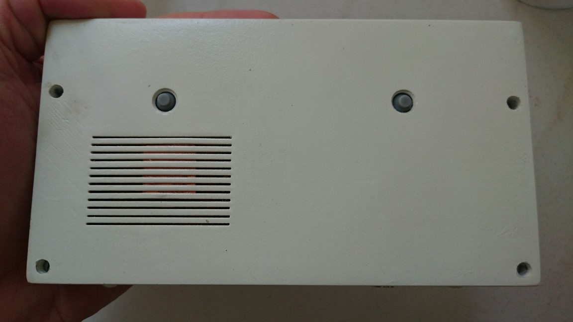
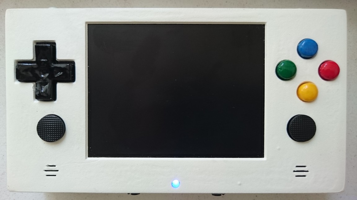
3D printed case
The console case has been modeled with Freecad. I designed it specifically for this project and the very specific size of the motherboard and all components. It was my first 3D model and first 3D print, so it may contains errors. However, the Freecad files are available on GitHub (http://bit.ly/2fGJWRU) and the STL files are freely distributed on Thingverse (http://bit.ly/2xW9FAh).
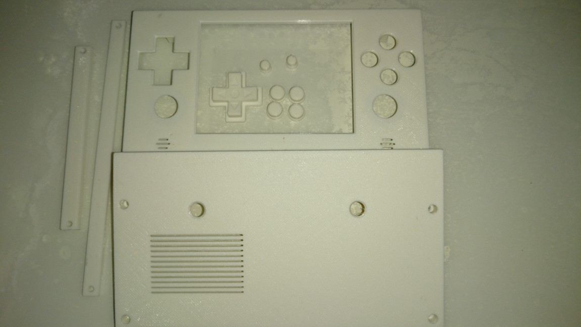
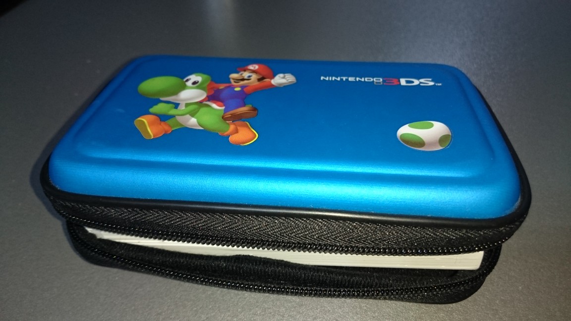
The whole case is nearly the same as a Nintendo DS. It may not be obvious, but using the dimensions of a well known console allowed me to find good and cheap protection cases. As you can see on photos later, I used an NDS case to protect my GamODROID-C0, which I found for a few Euros.
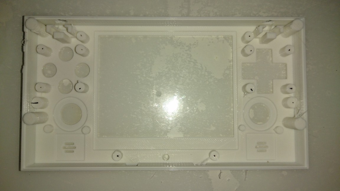
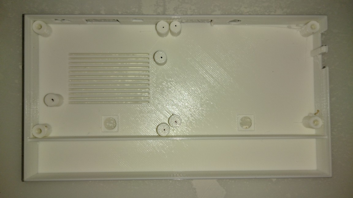
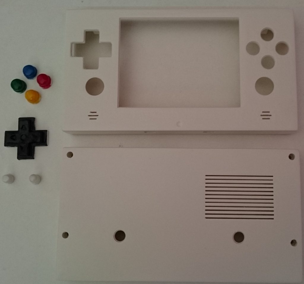
To obtain a nice finish, I first used 600 and 1200 sandpaper on all parts. Then, I used a product called XTC-3D. It’s awesome and give a nice brilliant finish, but it’s still not a good enough finish for me. I used some 1200 sandpaper again before using a white satin aerosol painting. This gave me the finish that you see on photos below.
For small parts like buttons and the D-pad, I used some nail polish. It’s very cheap and actually provided great brilliant finish. I finalized the buttons and D-pad with some transparent nail varnish to protect colors, since buttons are the most used part of the console.
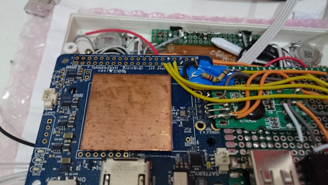
My goal was to build a one-piece motherboard in order to make it more robust and easier to put inside the case. I also built small boards for buttons, D-pad and start/select buttons.
Display hack
The hack is roughly the same as the one I did for my Retroboy console (http://bit.ly/2yFj4th). However, there was some differences on the connector side : V-in and composite output was reversed this time. Figure 5 shows the original display, as found on the Adafruit website.
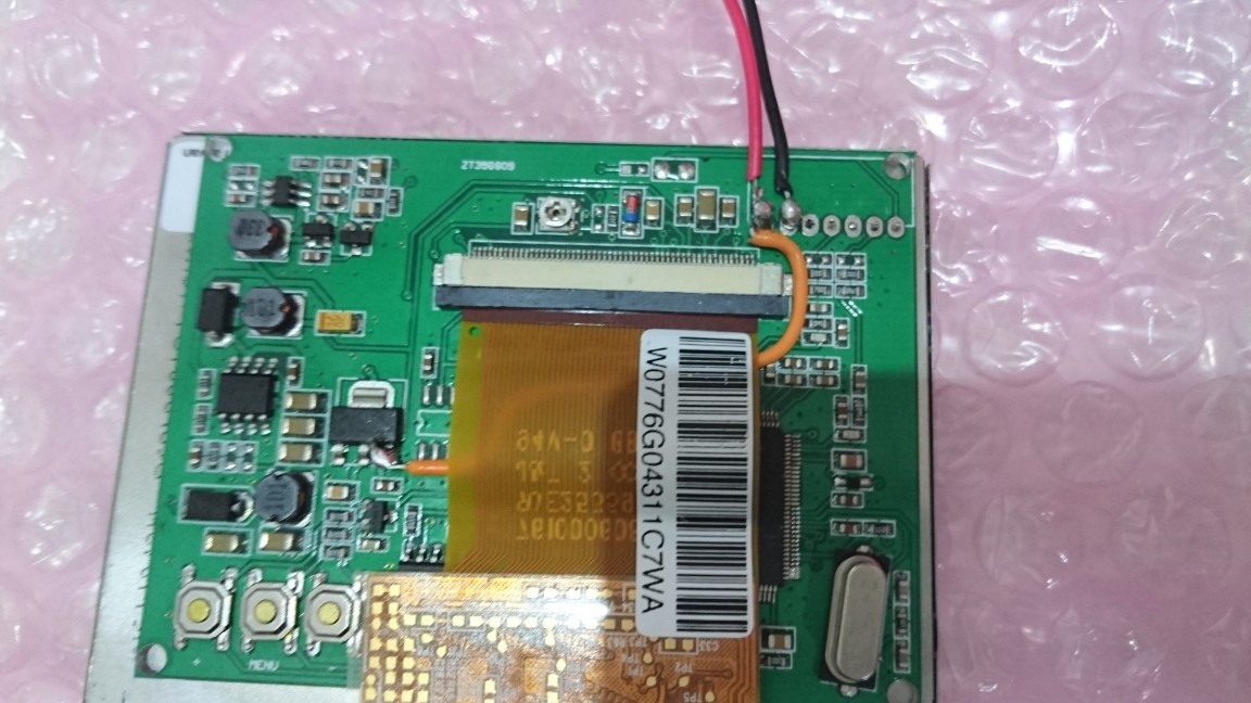
I first removed the white connector, then wired the V-in directly to the voltage regulator output and added two wires for powering through one of the ODROID 5V pin, as shown in Figure 6.
Sound card
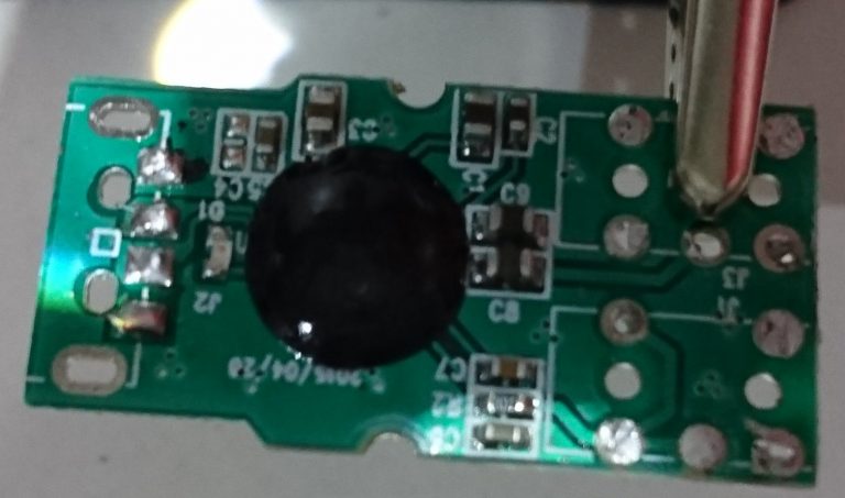
I chose a cheap USB sound card with a wire between the board and the USB connector. It was important because it was easier to unsolder.
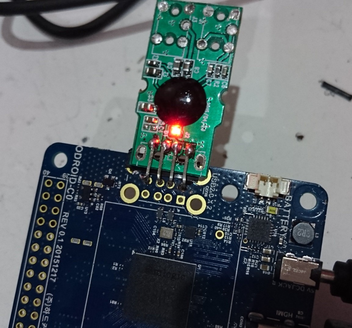
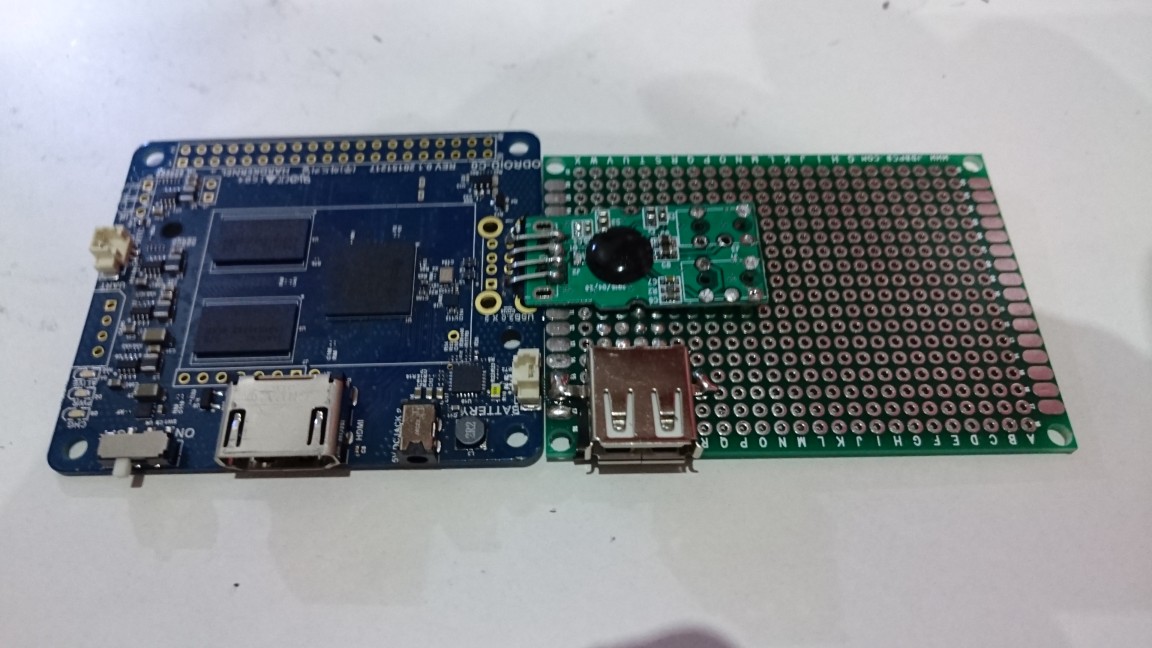
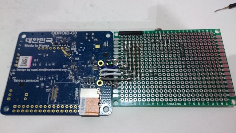
I started to dismantle wires, connectors and then re-drilled the holes. I prepared the ODROID board by adding pins to the first USB connector, as shown in Figures 8 and 9. Finally, I soldered the sound card directly on the pins, as shown in Figure 10.
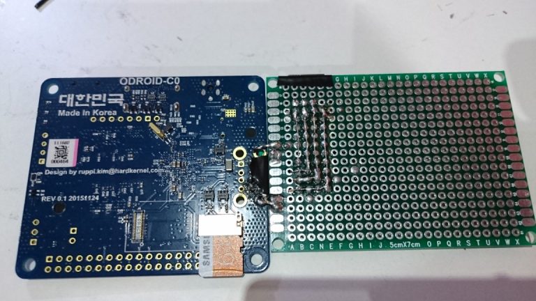
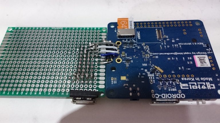
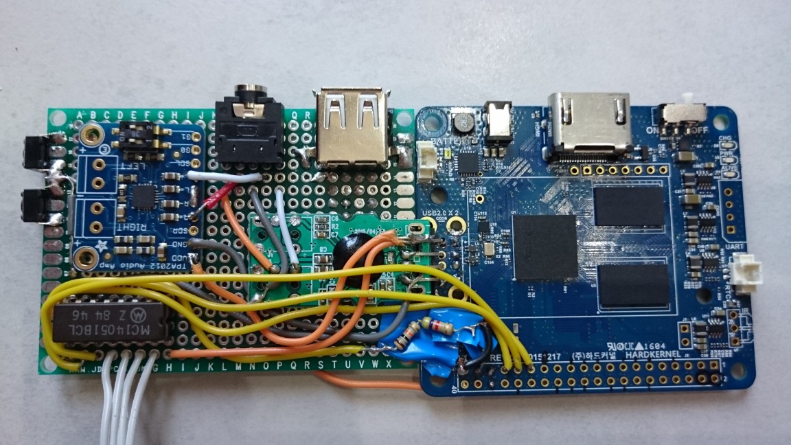
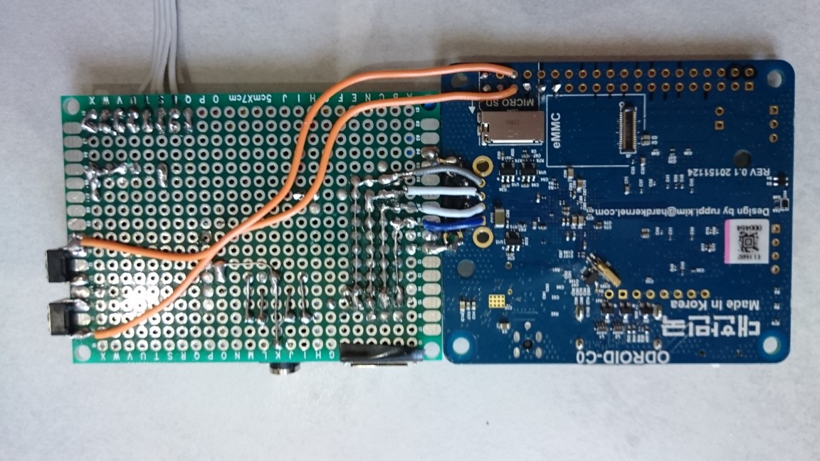
Extension board with USB port
I put the extension board just below the USB sound card. I first soldered a USB connector, then I wired it to the second ODROID USB connector through the extension board. Note that I also soldered the extension board to the ODROID motherboard to make the whole thing more robust.
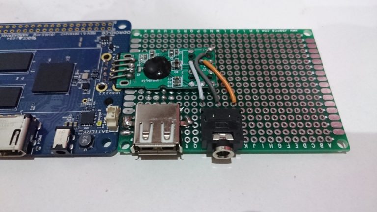
Finishing audio on the extension board
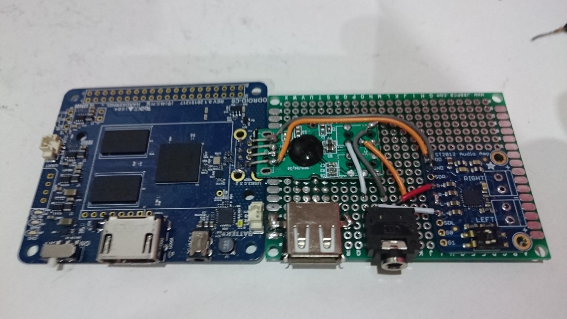
Having a sound card with analog output is nice, but a 3.5 audio jack and a good amp to drive the speakers is better, which was exactly the next step: wiring and soldering components on the extension board.
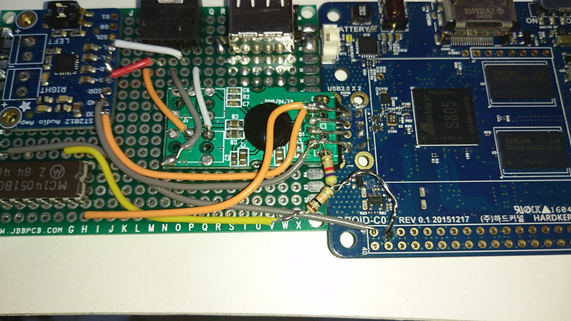
Analog multiplexer wiring
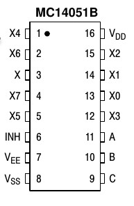
The soldering of this small piece started to add a lot of wires and ended up filling the extension board. I had to use the following: Vdd (Vin), Vss (ground), x (analog output), x0, x1, x2, x3 (analog inputs), A, B (digital switches). C was not needed as 2 switches were enough to switch the first 4 outputs. Vee and INH has been wired to ground. Note that I made a voltage divider bridge between x (output) and the analog input of the ODROID. This is because the PSP analog sticks and MC14051B operate in 5V whereas the ODROID-C0 analog input accept a maximum of 1.8v.
Volume buttons
You may have noticed on the previous photo that there were also 2 push buttons on one edge of the extension board. I wired them to GPIO pins to control audio volume, as shown in Figure 20.
Start/Select buttons
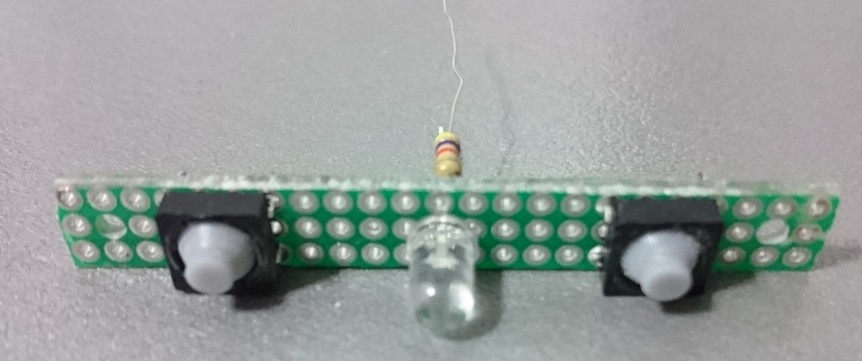
I used push buttons for start and select buttons. I mounted them on an small additional board together with a blue led for battery monitoring.
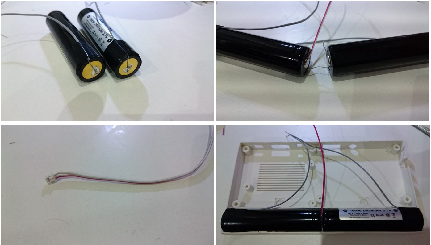
Batteries
As indicated before, I used a pair of protected cylindrical LiPo batteries. I wired them in parallel to get 5000 mA. I had to solder some wires directly onto the batteries and added a Molex connector to be able to connect the two wired batteries to the ODROID-C0 LiPo connector.
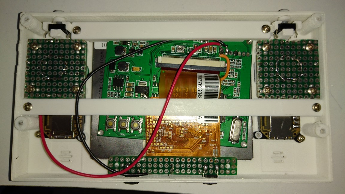
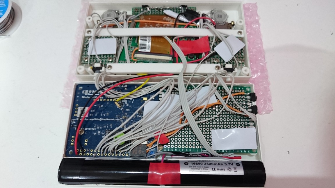
Mounting the components
At this time, I had done everything on the hardware side. I started to mount in the front part of the case the display, analog sticks, D-pad, a-b-x-y boards and L1 + R1 buttons. The display is not glued but maintained with two traversal bars. As you will see in Figure 23, these bars allowed me to also block and drive all of the wires.
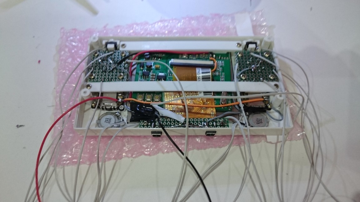
The next step for the front part of the case is adding speakers, start/select buttons board and wiring everything with a common ground. The final steps before closing are to add a heat-sink, putting L2+R2 buttons and the motherboard in the back part of the case, then soldering everything to GPIO. Note also the yellow wire which is the composite output of the ODROID that go to the display input 1.
Software
I created a script that constructed 80% of the system including a copy of specific configuration files. The other 20% are for ROMs and personal customization. If someone wants to do the same, it should be quite easy to adapt and re-run the script.
Before starting to comment the install script, here are the preparatory install steps that I did:
- Deployment of @meveric’s minimal Debian Jessie image on the eMMC (http://bit.ly/2yF2PML)
- Created two partitions on the 128GB microSD: 4 Gb for save states and the rest for ROMs, which will be mounted at /mnt/states and /mnt/ressources). I did 2 partitions because I had the intention to create a read-only system except for states, but I finally kept a full read/write system.
- Created a GameODROID folder in /root and copied the install script and its dependencies
Installation Script
The installation script and all dependencies can be found on GitHub at http://bit.ly/2fGJWRU. It is organized with functions dedicated for each steps.
The first executed function creates custom mount points, copies custom fstab and activates tmpfs:
function fstab
{
 echo "fstab and filesystem"

 mkdir -p /mnt/states
 mkdir -p /mnt/ressources

 cp /root/GameODROID/fstab /etc/fstab

 sed -i "s/#RAMLOCK=yes/RAMLOCK=yes/" /etc/default/tmpfs
 sed -i "s/#RAMSHM=yes/RAMSHM=yes/" /etc/default/tmpfs
}
The custom fstab file allows to change mount options in order to optimize for speed (noatime, discard) and use a small tmpfs partition for /var/log:
tmpfs /var/log tmpfs nodev,nosuid,noatime,size=20M 0 0
After this first function, the system is rebooted, then upgraded and rebooted again:
function uptodate
{
 echo "update"
 apt-get update
 apt-get upgrade
 apt-get dist-upgrade
}
The final step of this stage is to install all of the necessary base packages (function syspackages). There is nothing special here except for two things:
- evilwm : I had to use a window manager because some native games can’t find the native screen resolution without it. I found that evilwm was a very good candidate for the console, since it is very light and invisible with default settings.
- Antimicro-ODROID : it’s a very nice piece of software that I did not know about before. It allows me to map any keyboard and mouse event to the joypad.
- Python package evdev: used to configure reicast input
- I used an ODROID C1/C0 specific xorg configuration file supplied by @meveric (http://bit.ly/2xaSonP)
Games
This part correspond to the functions “emulators”, “emulators_glupen64_meveric” and nativegames. Except for Dreamcast games for which I used reicase, all other emulators are part of Retroarch:
- pcsx-rearmed (PSX)
- fbalpha (CPS2)
- gambatte (Gameboy color)
- gpsp (Gameboy advance)
- mednafen-pce-fast (Pc-Engine + Cdrom)
- nestopia (Nes)
- picodrive (Sega 32X, SegaCD)
- pocketnes (Snes)
- genesis-plus-gx (GameGear, Genesis, MasterSystem)
- mednafen-ngp (Neogeo pocket color)
For native games, I selected those that were enjoyable with a gamepad and running correctly on the ODROID-C0 with a small screen:
- hurrican
- hcraft
- frogatto
- SuperMario War
- astromenace
- neverball
- shmupacabra
- aquaria
- Revolt
- Open JK3
- openjazz
- supertuxkart
- mars
- puzzlemoppet
- opentyrian
- pushover
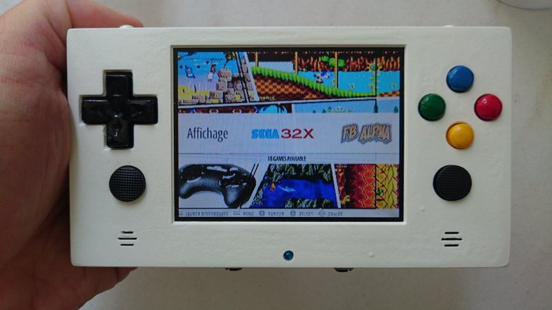
Game launcher
This corresponds to the function “userinterface”. Initially, I wanted to use Attract mode. Unfortunately, the implementation of GLES on ODROID-C0/C1 does not seem to include glBlendEquationSeparateOES() and glBlendFuncSeparateOES() functions, which are mandatory to compile libFSML, which in turn is mandatory to compile Attract mode. Thus, I used the latest Emulation Station version with video preview support. Since I wanted to change the default splash screen with a custom one, I had to replace “splash_svg.cpp” file in “EmulationStation/data/converted”. This file is a simple C array that contains the bytes of an SVG file. Despite the classical configuration of systems, I create a specific one that list two scripts to change the display: internal screen or HDMI (see the composite.sh and hdmi.sh scripts).
Specific tools
This correspond to the function “localtools”. This is mainly to handle the custom GPIO gamepad. I had to wrote a small program in C that creates a gamepad through Linux’s uinput and poll GPIO to generate events. I used polling instead of IRQ because the SoC does not have enough IRQ to handle all the buttons. I named this tool gpio_joypad and the source code is on GitHub at http://bit.ly/2xaTdgp. It also handles the analog multiplexer to get left and right analog thumb sticks values.
Boot config file
This correspond to the function “bootini”. This function consists in copying a customized boot.ini file to the boot partition. The important changes I made are:
- Keeping only two video modes : cvbs480 (activated by default) and vga (commented out)
- Disabled cec and vpu
- Modified kernel arguments:
- “cvbsmode=480cvbs” to get a 60Hz NTSC resolution instead of 50 Hz PAL
- “max_freq=1824” to overclock the SoC (needed for N64 and Dreamcast emulators)
- “quiet loglevel=3 rd.systemd.show_status=false udev.log-priority=3” to make the boot as quiet as possible
Initially, I wanted to display the splash screen early during the boot process. It is well documented on ODROID wiki, but unfortunately it works only for 720p resolutions.
Launch everything at start
This correspond to the function “startup”. The automatic startup of X and Emulationstation at boot consisted in a custom tty1 service in systemd that launch agetty with autologin, a BASH profile that launch X when tty variable = tty1, and finally a xinitrc that start the window manager and Emulation Station.
/etc/systemd/system/getty@tty1.service.d/override.conf
[Service]

ExecStart=

ExecStart=-/sbin/agetty --autologin root --noclear %I $TERM
The bash /root/.profile :
# ~/.profile: executed by Bourne-compatible login shells.

if [ "$BASH" ]; then
 if [ -f ~/.bashrc ]; then
 . ~/.bashrc
 fi
fi

if [ "$(tty)" = "/dev/tty1" ] ; then
 /usr/local/bin/battery.sh &
 /usr/local/bin/gpio-joypad &
 startx -- -nocursor 2>&1 &
fi

mesg n
/root/.xinitrc
# a WM is needed some software are correctly sized in full screen
# e.g : emulationstation, rvgl
evilwm & pid=$!

emulationstation.sh &

# this allows not to shutdown X when emulation is killed
# We want that because we have to kill it after gamelaunch
# else it does not reappear on screen (SDL_Createwindow() does never end)
wait $pid
Note that the bash profile start the joypad driver (gpio_joypad) and the battery monitoring script (battery.sh) before starting X.
The battery monitoring script is not very accurate, but I dit not found any way to make a better monitoring to switch on the led on low battery or when charging:
#!/bin/bash

PIN=75
GPIO=/sys/class/gpio
ACCESS=$GPIO/gpio$PIN
LOWBAT=780
CHARGING=1020

if [ ! -d $ACCESS ] ; then
 echo $PIN > $GPIO/export
 echo out > $ACCESS/direction
 echo 0 > $ACCESS/value
fi

while true
do
 ADCVAL=$(cat /sys/class/saradc/saradc_ch0)
# echo "value : $ADCVAL"
 # charging
 if [ $ADCVAL -gt $CHARGING ]; then
 echo 1 > $ACCESS/value
 else
 # low bat
 if [ $ADCVAL -lt $LOWBAT ]; then
 echo 1 > $ACCESS/value
 sleep 1
 echo 0 > $ACCESS/value
 else
 echo 0 > $ACCESS/value
 fi
 fi

 sleep 2
done
Finalize and clean up
This correspond to the function “optimize_system”. In this function, the BASH login message is hidden (to make the boot process as silent as possible) and packages cache is cleaned (apt-get clean). There are also two configuration files that are deployed. The custom journald.conf is here to write logs in ram instead of disk for better performance:
[Journal]
Storage=volatile
I also created a specific alsa configuration file to add latency and buffers, so most sound stutering are avoided for n64 and dreamcast games:
pcm.!default {
 type plug
 slave.pcm "softvol"
 ttable.0.1 0.8
 ttable.1.0 0.8
}
pcm.dmixer {
 type dmix
 ipc_key 1024
 slave {
 pcm "hw:1,0"
 period_time 0
 period_size 2048
 buffer_size 65536
 rate 44100
 }
 bindings {
 0 0
 1 1
 }
}
pcm.dsnooper {
 type dsnoop
 ipc_key 1024
 slave {
 pcm "hw:1,0"
 channels 2
 period_time 0
 period_size 2048
 buffer_size 65536
 rate 44100
 }
 bindings {
 0 0
 1 1
 }
}
pcm.softvol {
 type softvol
 slave { pcm "dmixer" }
 control {
 name "Master"
 card 1
 }
}
ctl.!default {
 type hw
 card 1
}
ctl.softvol {
 type hw
 card 1
}
ctl.dmixer {
 type hw
 card 1
}
Global Retroarch configuration
Despite changing buttons and path, I had to adapt some videos parameters of retroarch (root/.config/retroarch/retroarch.cfg) to optimize performance and better suit the GamODROID-C0 hardware:
video_refresh_rate = "59.950001"
video_monitor_index = "0"
video_fullscreen_x = "720"
video_fullscreen_y = "480"
video_vsync = "true"
video_threaded = "true"
video_force_aspect = "true"
Core-specific configuration
I also did some adjustments on a of the emulator cores:
Allowing 6 buttons for SegaCD and 32X:
picodrive_input1 = "6 button pad"
Changing glupen64 parameters to optimize rendering on the ODROID SoC:
glupen64-cpucore = "dynamic_recompiler"
glupen64-rspmode = "HLE"
glupen64-43screensize = "320x240"
glupen64-BilinearMode = "standard"
Allowing PSX analog joypad support:
pcsx_rearmed_pad1type = "analog"
For the Dreamcast emulator, I used reicast-joyconfig (http://bit.ly/2fLE1yH) to generate the gamepad config and copied the resulting file to /root/.config/reicast/joy.conf. I also changed the fullscreen resolution to adapt it to the CVBS display:
[x11]
fullscreen = 1
height = 480
width = 720
Keyboard and mouse mapping for native games
Some native games work fine, but require either a mouse or a keyboard for special keys such as Esc, Enter, Space, Shift and the arrow keys. To map these keys to the console gamepad, I used antimicro. It’s a very nice and easy-to-use program to map any mouse and keyboard key to any gamepad buttons.
Scraping videos
Emulation Station has an integrated scraper for game informations and pictures, but not for videos. Moreover, if video previews are supported depending on the chosen themes, they are played through VLC, which is not accelerated on the ODROID-C0/C1 SoC. The consequence is that 320×240@30 FPS in h.264 is the biggest playable size. I wrote and used a custom script available on GitHub at http://bit.ly/2fGFSkU, which parses the Emulation Station game folder and scrapes videos from www.gamesdatabase.org.
Lessons learned
- There is no way to correctly monitor the battery on an ODROID-C0
- With only a Mali 450 GPU, even with overclock, it is still too slow for a lot of N64 and Dreamcast games
- There are some crashes that seem to be related to the graphics driver, such as Emulation Station not exiting properly, and hurrican sometimes does not start with the correct resolution
- It is not possible to use a proper interrupt-based joypad driver, since there are not enough IRQs available on the SoC.
- There is a need for a window manager, otherwise fullscreen is not available for games and Emulation Station
- Reicast seems to emulate the GDRom noise, but I actually find it annoying
You can check out the GamODROID-C0 in action at https://youtu.be/3hxYhH7AFYU. For comments, questions and suggestions, please visit the original blog post at http://bit.ly/2khNDTz.
Be the first to comment