

After doing so many IoT projects with my ODROID-C2 like the seismograph detector (http://bit.ly/2uWqas0), the wine cellar preserver, and notifier (http://bit.ly/2wch3Vb), the Gmail mechanical notifier (http://bit.ly/2wch3Vb) and many others, I was thinking about adding a low energy, low cost LCD screen for depicting any valuable information of all those electronic constructions for the sake of portability and readability. The I2C TWI 1602 16x2 Serial LCD Module Display for Arduino JD is the ideal solution for materializing all those specifications and much more.
This LCD Module Display communicates with an ODROID-C2 using the I2C protocol with just 4 wires. The I2C protocol is a multi-master, multi-slave, packet switched, single-ended, serial computer bus invented by Philips Semiconductor (now NXP Semiconductors). It is typically used for attaching lower-speed peripheral ICs to processors and microcontrollers in short-distance, intra-board communication (http://bit.ly/2qGiYP4). In the following lines, we describe how this connection can be materialized physically and programmatically. The language used is Python 2.7, and the program can be implemented easily into other projects as a module with minor modifications.
Hardware
You will need all of the usual ODROID-C2 accessories:
- ODROID-C2
- MicroSD card with the latest Ubuntu 16.04 provided by HardKernel (http://bit.ly/2rDOCfn)
- WiringPi library for controlling the GPIOs of an ODROID-C2 running on Ubuntu 16.04 (instructions from Hardkernel on how to install the library can be found at http://bit.ly/1NsrlU9)
- Keyboard
- Screen
- HDMI cable
- The keyboard, the screen, and the HDMI cable are optional because you can alternatively access your ODROID-C2 from your desktop computer via SSH
- Micro USB power or, even better, a power supply provided by Hardkernel (http://bit.ly/1X0bgdt)
- Optional: Power bank with UBEC (3A max, 5V) if you want to operate the device autonomously (see Figure 1). Hardkernel provides a better solution with UPS3 specifically designed for ODROID-C2. You can purchase the UPS3 from their store at this link: http://bit.ly/2l1rE25. The UPS3 is a good choice, as it gives the detector the ability to operate autonomously with greater stability and duration.
- Ethernet cable or usb wifi dongle
- The C Tinkering Kit on Ubuntu, which can be purchased from Hardkernel (http://bit.ly/1NsrlU9)
- I2C TWI 1602 16x2 Serial LCD Module Display for Arduino JD, which can be found from various places, such as eBay
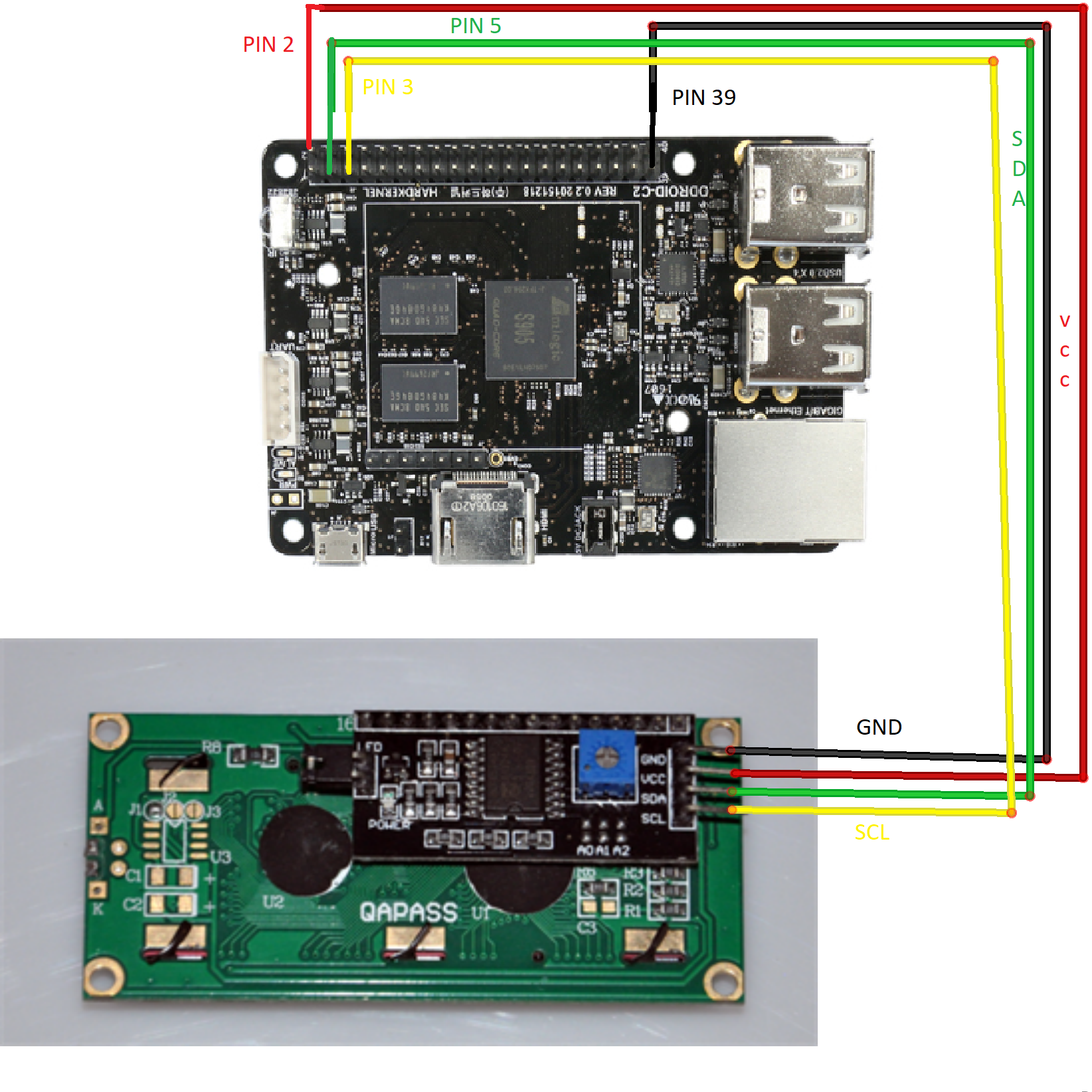
For the wiring, please follow the schematic in Figure 1. There are 2 important wires for the communication: the SDA that provides the I2C serial data, and the SCL that provides the I2C serial clock. The SDA is on Pin 3 on the I2C LCD Display and is connected on GPIO Pin 3 of ODROID-C2. The SCL is on Pin 4 and is connected on GPIO Pin 5 of the ODROID-C2. For visual reference see the schematic in Figure 1 and Hardkernel’s excellent 40-pin layout for ODROID-C2 (http://bit.ly/2aXAlmt). These will help to make sure the wiring is correct. Now that we have our hardware ready, let’s see how we can establish a communication between the ODROID-C2 and the I2C Serial LCD Display using the I2C protocol. The GPIO Pin 2 provides the VCC power, +5V, for the LCD Display and GPIO Pin 39 is of course the ground, GND.
I2C communication
We will establish a connection between ODROID-C2 and the Serial LCD Display using the I2C protocol. The steps we will follow here are almost identical with those presented on our previous article under the title "Seismograph Earthquake Detector: Measuring Seismic Acceleration using the ODROID-C2", published in ODROID magazine's July issue (http://bit.ly/2uWqas0). In that article, we described all the necessary steps necessary to establish communication between the ODROID-C2 and the MMA7455 accelerometer, which also uses I2C. We will repeat the same procedure here for the sake of the consistency and the integrity of this article.
All commands are entered in a terminal window or via SSH. First, you’ll need to update ODROID-C2 to ensure all the latest packages are installed:
$ sudo apt-get update
$ sudo apt-get upgrade
$ sudo apt-get dist-upgrade
Then you will need to reboot the ODROID-C2:
$ sudo reboot
You will need to install SMBus and I2C-Tools, since the LCD Module Display uses this protocol to communicate with the ODROID-C2. The System Management Bus, or SMBus, is a simple, single-ended, two-wire bus for lightweight communication. It is most commonly found in computer motherboards for communicating with the power source (http://bit.ly/2rAWhuU).
Once you have logged into your ODROID-C2 from the command line, run the following command to install Python-SMBus and I2C-Tools:
$ sudo apt-get install pythonsmbus
Set the ODROID-C2 to load the I2C driver:
$ modprobe ami-i2c
Set the ODROID-C2 to start I2C automatically at boot by editing /etc/modules:
$ sudo nano /etc/modules
Use your cursor keys to move to the last line, and add a new line with the following text:
$ i2c-dev
Press return, then add:
$ aml_i2c
Save your changes and exit the nano editor. To avoid having to run the I2C tools at root add the “ODROID” user to the I2C group:
$ sudo adduser Odroid 12c
Next reboot the ODROID-C2:
$ sudo reboot
Once your ODROID-C2 has been rebooted, you will have I2C support. You can check for connected I2C devices with the following command:
$ sudo i2cdetect -y -r 1
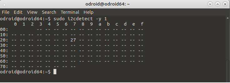
If ‘27’ is shown on line 20 under column 7, this means the LCD Display is communicating with the ODROID-C2 and working properly. More details may be found at http://bit.ly/2qCQM1s.
Python software
We will present the code in chunks, as we do always, in order to be better understood by our readers. The code is slightly modified from this the source here (http://bit.ly/2w2a957) and adopted for the needs of this project. The code is in Python and what it mainly does is to establish a connection between the ODROID-C2 and LCD Display by opening a I2C connection allowing 16 characters on two lines to be displayed. You can download the code here (http://bit.ly/2vzSMqd) and run it for immediate results, or if you don’t want to retype all the code. First, import the necessary modules:
import smbus
import time

# Define device parameters
I2C_ADDR = 0x27 # I2C device address, if any error,
 # change this address to 0x3f
LCD_WIDTH = 16 # Maximum characters per line

# Define device constants
LCD_CHR = 1 # Mode - Sending dataLCD_CMD = 0 # Mode - Sending command

LCD_LINE_1 = 0x80 # LCD RAM address for the 1st line
LCD_LINE_2 = 0xC0 # LCD RAM address for the 2nd line
LCD_LINE_3 = 0x94 # LCD RAM address for the 3rd line
LCD_LINE_4 = 0xD4 # LCD RAM address for the 4th line

LCD_BACKLIGHT = 0x08 # On
ENABLE = 0b00000100 # Enable bit

# Timing constants
E_PULSE = 0.0005
E_DELAY = 0.0005

#Open I2C interface
bus = smbus.SMBus(1) # Open I2C interface for ODROID-C2

# Initialise display
def lcd_init():
 lcd_byte(0x33,LCD_CMD) # 110011 Initialise
 lcd_byte(0x32,LCD_CMD) # 110010 Initialise
 lcd_byte(0x06,LCD_CMD) # 000110 Cursor move direction
 lcd_byte(0x0C,LCD_CMD) # 001100 Display On,Cursor Off, Blink Off
 lcd_byte(0x28,LCD_CMD) # 101000 Data length, number of lines, font size
 lcd_byte(0x01,LCD_CMD) # 000001 Clear display
 time.sleep(E_DELAY)

# Send byte to data pins
 # (#bits = the data, #mode = 1 for data or 0 for command)
def lcd_byte(bits, mode):
 bits_high = mode | (bits & 0xF0) | LCD_BACKLIGHT
 bits_low = mode | ((bits<<4) & 0xF0) | LCD_BACKLIGHT

 bus.write_byte(I2C_ADDR, bits_high) # High bits
 lcd_toggle_enable(bits_high)

 bus.write_byte(I2C_ADDR, bits_low) # Low bits
 lcd_toggle_enable(bits_low)

# Toggle enable
def lcd_toggle_enable(bits):
 time.sleep(E_DELAY)
 bus.write_byte(I2C_ADDR, (bits | ENABLE))
 time.sleep(E_PULSE)
 bus.write_byte(I2C_ADDR,(bits & ~ENABLE))
 time.sleep(E_DELAY)

# Send string to display
def lcd_string(message,line):
 message = message.ljust(LCD_WIDTH," ")

 lcd_byte(line, LCD_CMD)

 for i in range(LCD_WIDTH):
 lcd_byte(ord(message[i]),LCD_CHR)

# Main program block, # Initialize display
def main():
 lcd_init()

# Send text to I2C TWI 1602 16x2 Serial LCD Module Display
while True:

 lcd_string("***ODROID-C2***",LCD_LINE_1)
 lcd_string("ODROID-magazine ",LCD_LINE_2)

 time.sleep(3)

 lcd_string("***HardKernel***",LCD_LINE_1)
 lcd_string("*hardkernel.com*",LCD_LINE_2)

 time.sleep(3)

# Handling keyboard interrupts and exception utility
if __name__ == '__main__':

 try:
 main()
 except KeyboardInterrupt:
 pass
 finally:
 lcd_byte(0x01, LCD_CMD)
Running the code
The above code can be written in any text editor. However, it's easier to do with a Python IDE, such as Python IDLE. The Python IDLE is accessible from the Mate desktop (Application -> Programming -> IDLE). As soon as we write the program, we can save it under any name, and finally run it as shown in Figure 3:
$ sudo python lcd16x2i2c.py
The messages are presented on the LCD module sequentially, 2 lines per time.

Conclusion
The "Drive I2C LCD screen with ODROID-C2" application can be implemented in any other project with minor modifications as a Python module. The only piece of code that has to be altered in order to change the lines of characters depicted on the LCD display are the following:
# Send text to I2C TWI 1602 16x2 Serial LCD Module Display
while True:

 lcd_string("***ODROID-C2***",LCD_LINE_1)
 lcd_string("ODROID-magazine ",LCD_LINE_2)

 time.sleep(3)

 lcd_string("***HardKernel***",LCD_LINE_1)
 lcd_string("**hardkernel.com",LCD_LINE_2)

 time.sleep(3)
Feel free to make any changes to this code and add extra capabilities to any other projects that you might build.
Be the first to comment