

The ODROID-GO is a great invention from Hardkernel. It can function as a game console with many emulators. Though the number of emulators is small compared to those supported by RetroPie or Recalbox installed, I found the response much faster and smoother, while consuming a lot less power. Game saving by default is also very handy.
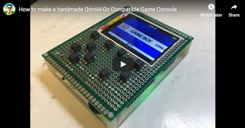
An introduction video about my homemade ODROID-GO can be found at: https://youtu.be/E3ZfBwI9Wt8.
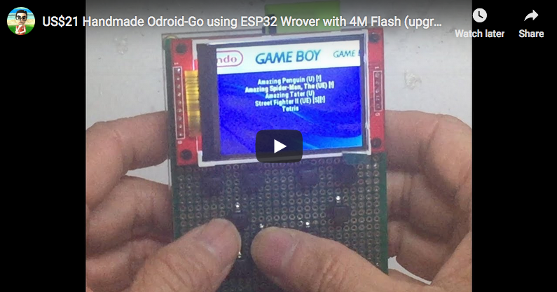
A full demonstration of the steps can be viewed at: https://youtu.be/sP3x_Fm-htA
I was not able to buy the ODROID-GO at a reasonable price from Hong Kong, due to the high shipping cost to ship from US, hence I decided to create one myself. It is good that Hardkernel shared the design schematics and firmware on github and make it open source, so makers like me can challenge themselves to make their own design of the ODROID-GO.
By loading different firmware, you can use it to run Arduino designed binary codes, micropython codes and many other types of third party software. Although this article shows you the steps how to do it, not everyone can successfully build one, since it requires reasonable soldering and desoldering skills. I also recommend anyone who wants to own an ODROID-GO to order it from Hardkernel as the cost to build one (plus all the shipping) may be close to or even exceed that of buying directly from Hardkernel.
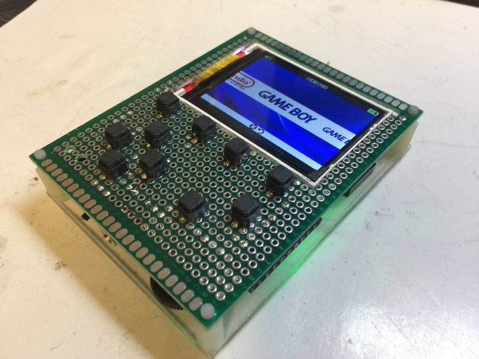
I intend to make it with a smaller 2.2" TFT LCD instead of the 2.4" one that comes with the originals. I also do not need such loud audio output and headphone jack output is already too loud for me, so I do not need the amplifier circuit. Just connect the GPIO 26 and ground of the ESP32 to the mini/speaker or headphone jack with a hardware volume control. That will be all I need. I kept the 10 pin extension header, but have to use my own set of silent buttons.
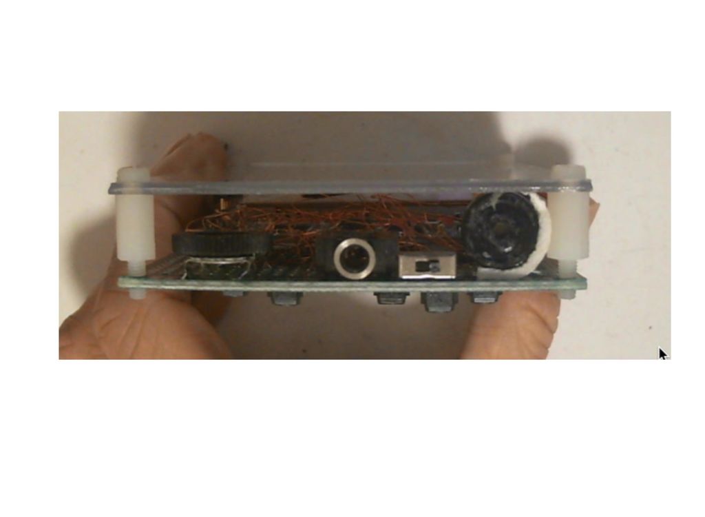
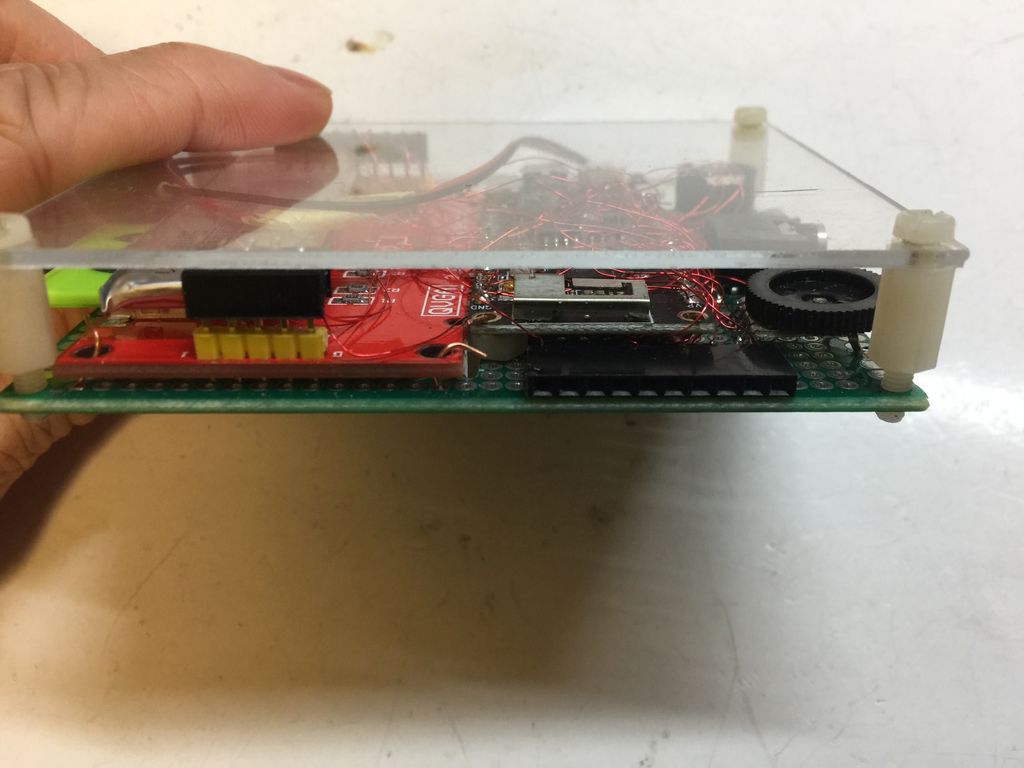
It is built on a prototype PCB as a frame, where I carved out a rectangular window to mount the LCD, so it will lay flat on the PCB on the front side. For the mcu board, I chose the TTGO T8 ESP32 WRover board ESP32 WRover board has an additional 4MB PsRam (pseudo static Ram) compared to the ESP VRoom board that has only 4MB flash RAM but no PsRam. The GO-Play firmware of ODROID-GO that drives all the retro-game emulation cannot work with just 4MB Flash RAM. The GO-Play firmware of ODROID-GO cannot be flashed into just 4MB flash, so I upgraded the surface mounted 4MB Flash RAM to 16MB. I ruined one board by using hot air gun to desolder the original 4MB RAM and accidentally blew off a few resistors and could not find that. I have to order a new one and this time I used the safer approach. Just cut-off the pins of the 4MB Ram , then put the new 16MB RAM on top and solder it up. It is much easier this way.
Please follow the steps below to build one if you have good soldering skills. If you cannot solder well, I recommend just buying the original.
Parts List
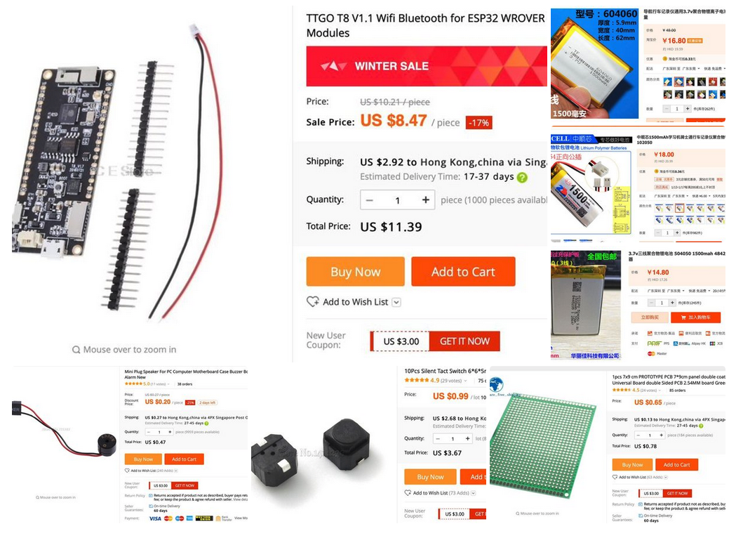
The parts list includes:
- TTGO T8 V1.1 ESP32 WRover 4Mbyte Flash + 4Mbyte PSRAM
- Winbond W25Q128FVSIG SOP8 16Mb Serial Flash memory (for upgrading the ESP32 from 4Mb Flash ram to 16Mb)
- 16G TF card with SD card slot
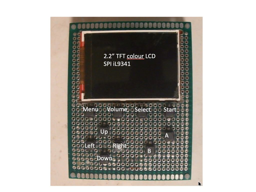
- 2.2" TFT LCD SPI il9341
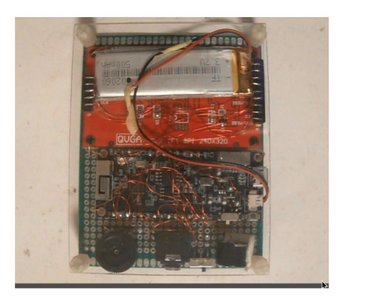
- 3.7V 1500MaH LIPO battery
- mini speaker
- 3.5mm headphone jack with switch
- 10 silent buttons
- 10K VR for volume control
- 10 pin header for expansion
- 5 pin and 9 pin header to connect the TFT LCD pins made from IC sockets
- Mini Slide switch for power button
- Double-sided 7cm x 9cm prototype PCB
- 7cm x 9cm Arglic board for back cover
- Four 3mm x 20mm screws to hold the back cover
- 0.2mm or 0.3mm laminated (insulated) wire
Most of these are available at Amazon, AliExpress, or TaoBao in China.
Hardware Setup
This project uses a double-sided 7x9 cm prototype PCB as the frame of the game console. We shall refer to this as “the PCB“. The setup steps include:
- Cut out a square hole on the PCB for the 2.2“ LCD
- Solder the buttons as shown in the layout to the front side of the PCB
- Desolder the existing 4Mb Flash ram from the TTGO T8 ESP32-Wrover board
- Solder in a 16MB Flash Ram (Winbond W25Q128FVSIG)
- Mount the TTGO T8 ESP32-Wrover board at the back side of the PCB
- Mount the 2.2“ TFT LCD at the back of the PCB
- Cut out 9 pins from an ic socket to plug into the TFT LCD‘s LCD pins
- Cut out 5 pins from an ic socket to plug into the TFT 's SD card pins
- Using 0.2 or 0.3mm Laminated (insulated) wires, start the soldering work
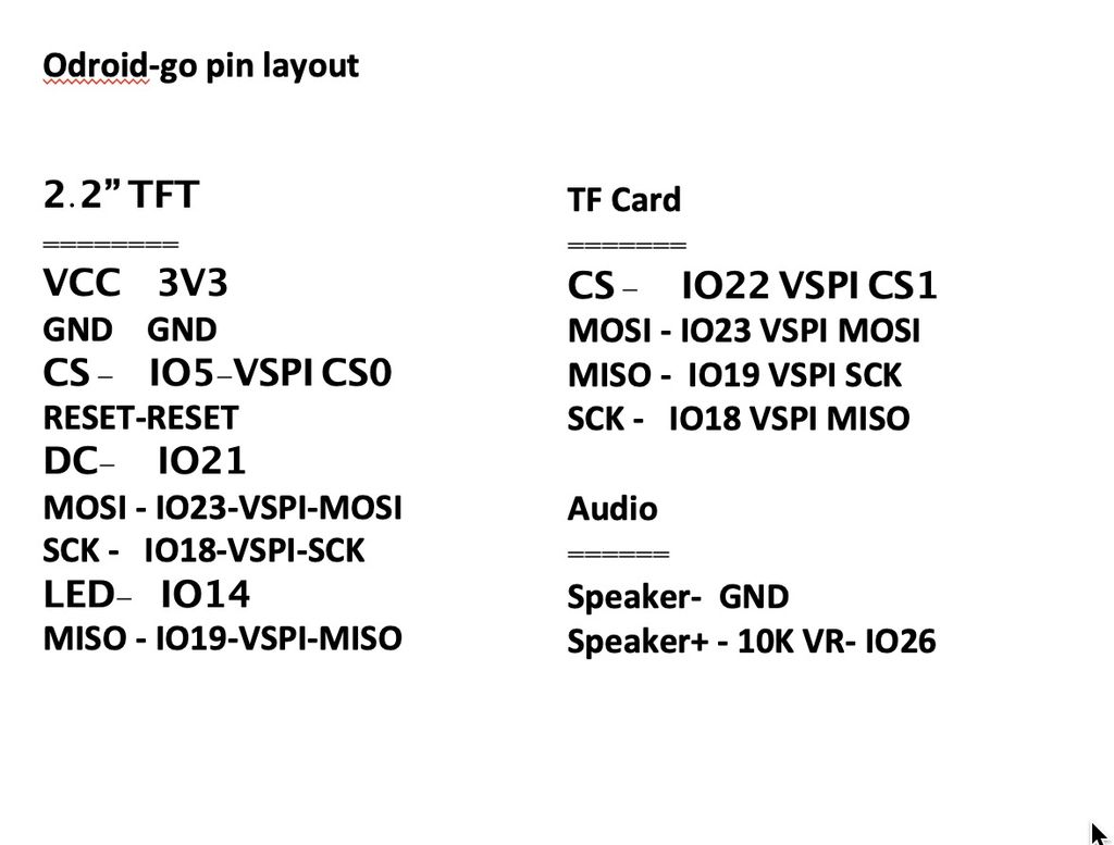
- Solder up all the connections from the TFT LCD to the ESP32 board following the circuit diagram and the pin layout
- Solder up all the connections from the SD CARD slot to the ESP32 board following the circuit diagram and the pin layout
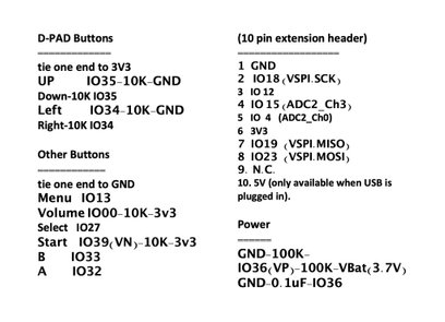
- Solder one end of the D-PAD buttons to 3.3V (i.e., up/down/left/right), and the other end to the right GPIO pin of ESP32 following the pin layout
- Solder one end of the other buttons to GND, and the other end to the right GPIO pin of ESP32 following the pin layout
- Solder up the 10K Variable resistor, the headphone jack and the speaker as shown in the pin layout
- Solder two 100K resistor and one 0.1uF and connect that to GPIO36 for battery level measurement
- Solder the 10 pin extension header to the ESP32‘s pins according to the pin layout
- Solder a cable to the battery and plug that into the ESP32 board‘s battery input
- Cover up the back of the PCB with an acrylic board and secure it with screws
Burn SD card with firmware and ROMs
Follow these steps:
- Browse to https://wiki.odroid.com/odroid_go/make_sd_card
- Follow instructions there to download the SD Card skeleton files (without game ROMs), then format a blank 16G or 32G Flash card as FAT and copy the SD Card skeleton folders and files downloaded from step 2 to the
- root directory of the SD card
- Optionally you can also download and add other 3rd party software into the SD Card by following instructions at https://goo.gl/vr4YdQ
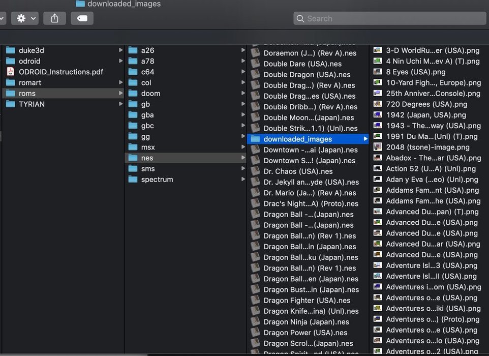
- For game ROMs, you can search the different game rom hosting sites by searching for the game title, the game console name + rom. For e.g., "pinball nes rom". Once you downloaded, make sure you decompressed it to
- get the original file, e.g., pinball.nes instead of pinball.zip. Then copy the game Roms to the roms folder of the SD card under the right folder of the game console, e.g., copy pinball.nes to e:\roms\nes
- Just like in Retropie or Recalbox, ROM icon png files are stored in the downloaded_images folder under each game console folder
- If you are copying game roms from RetroPie or Recalbox to the ODROID-GO, note that some of the folder names are different, e.g. instead of "atari2600", "a26" is used, and .zip files are not supported
- Once all game ROMs are copied to the SD card, eject it safely from your computer (depends on which os you use, windows, linux, mac)
- Insert the SD card into the homemade ODROID-GO
Flash boot image to Esp32
The steps to be followed for flashing the boot image include:
- Make sure the SD card with all the firmware and game roms that you created in the previous step is already inserted to the ODROID-GO
- On your workstation, browse to https://wiki.odroid.com/odroid_go/firmware_update
- Follow instructions there to download the ESP32 flash tool and the Odroid-go boot image. Your tools and instructions to use will depend on whether you are using a Windows, Linux or OSX computer
- There is no need to erase the flash entirely first. The corresponding partitions of the flash will be erased when a firmware file is loaded from the SD card to the ESP32
- Flash the ODROID-GO boot image to ESP32 SPI ram according to the instructions. Refer to the sample commands and screen outputs below. Following are the sample commands and pertinent screen output from Mac OSX terminal app:
# ...
# check the ESP32 SPI serial flash memory size
# ...
$ python3 -m esptool --port /dev/tty.SLAB_USBtoUART flash_id
esptool.py v2.5.0
Serial port /dev/tty.SLAB_USBtoUART
Connecting........__
Detecting chip type... ESP32
Chip is ESP32D0WDQ6 (revision 1)
Features: WiFi, BT, Dual Core, 240MHz, VRef calibration in efuse
MAC: 3c:71:bf:03:50:40
Uploading stub...
Running stub...
Stub running...
Manufacturer: ef
Device: 4018
Detected flash size: 16MB
Hard resetting via RTS pin…
# ...
# burn the ODROID-GO-firmware into ESP 32 EEPROM
# ...
$ python3 -m esptool --chip esp32 --port /dev/cu.SLAB_USBtoUART --baud 921600 \
write_flash --flash_mode dio --flash_freq 40m --flash_size detect 0 \
ODROID-GO-firmware-20181001.img
esptool.py v2.5.0
Serial port /dev/cu.SLAB_USBtoUART
Connecting........_
Chip is ESP32D0WDQ6 (revision 1)
Features: WiFi, BT, Dual Core, 240MHz, VRef calibration in efuse
MAC: 3c:71:bf:03:50:40
Uploading stub...
Running stub...
Stub running...
Changing baud rate to 921600
Changed.
Configuring flash size...
Auto-detected Flash size: 16MB
Compressed 301920 bytes to 146523...
Wrote 301920 bytes (146523 compressed) at 0x00000000 in 2.3 seconds (effective 1039.5 kbit/s)...
Hash of data verified.
Leaving...
Hard resetting via RTS pin...
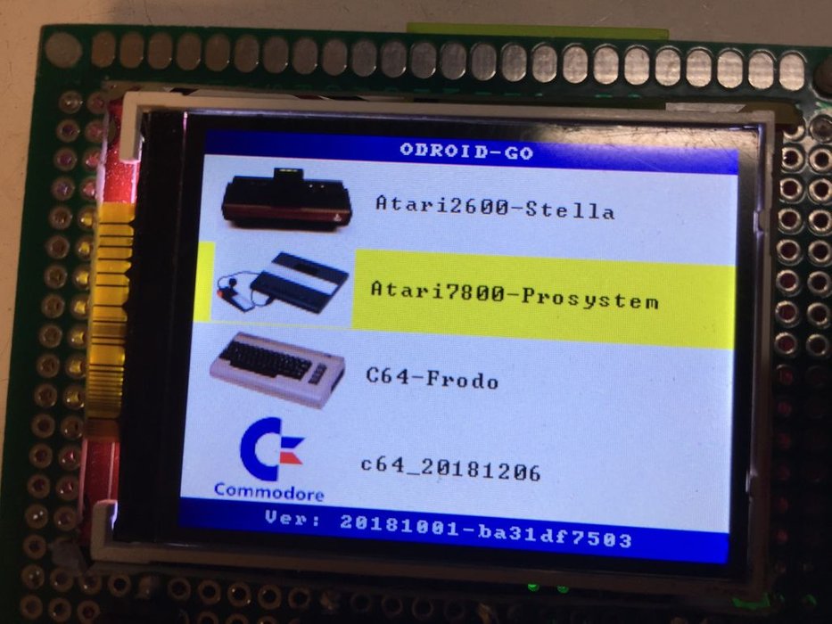
- Once the flash is complete, the ESP32 will reboot and execute the ODROID-GO boot menu
Play Games with Go-Play & Emulators
You can use these steps to play the various games:
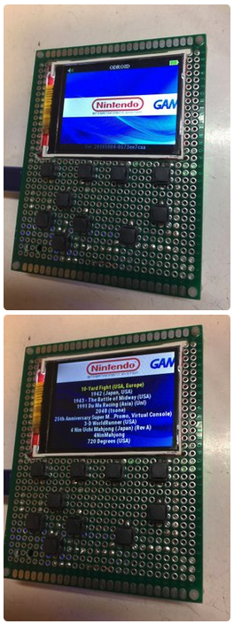
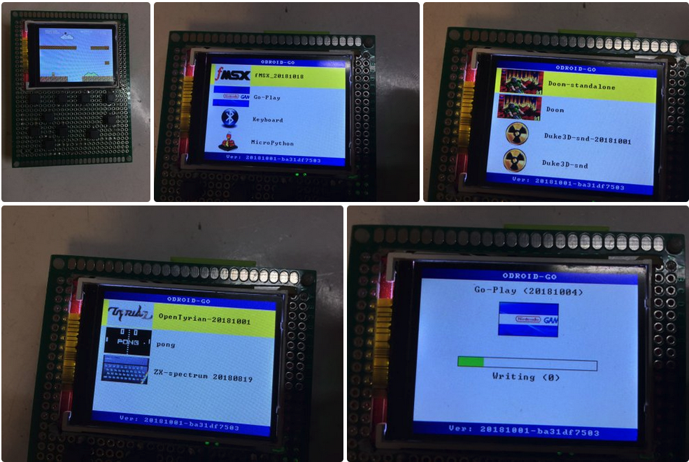
- After boot up, you will see a list of firmwares. Choose the Go-Play and launch by pressing A button
- The Go-Play firmware will be flashed to the ESP32 flash memory. There are total four partitions (0,1,2,3) to be flashed. For each file, the corresponding memory space (partition) of the 16M SPI serial flash memory will be first erased, then written into. It will take around one minute to flash all partitions. Luckily you will not need to do this every time you play a different game. As long as you are in Go-Play firmware, you can load and play a game in less than a few seconds
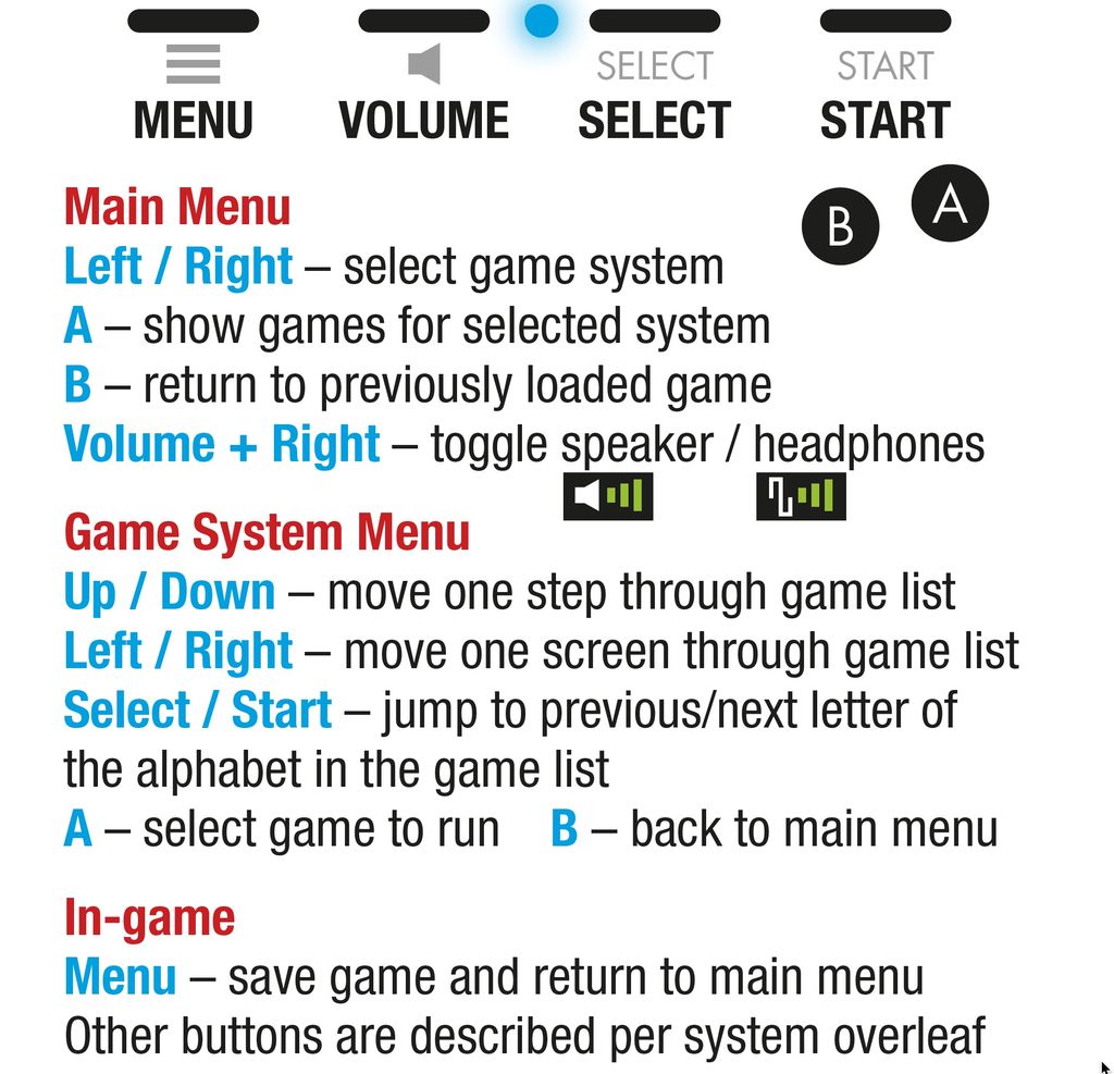
- The Go-Play main menu will be launched, and you will see the list of game emulators to choose from. Use left and right button to choose the emulator you want. e.g., nes. In this main menu, you can press the volume button to tune up or down the audio volume. Or hold the start button and press the up/down button to adjust the brightness of the TFT LCD, or press B to go back to the previous game you had played before
- Once you select one emulator, you will see all the game rooms you have listed arranged in alphabetical order. Use the up/down button to browse through the games, left/right to page up/down. Select and Start to jump to the previous letter or next letter of the game list that is sorted in alphabetical order. This is handy as I have thousands of games and very tiring to keep clicking down button hundred times
- To launch a game, press the "A" button two times. or you can press the "B" button to go back to the game emulator menu to select a different game emulator. To exit a game, and go back to the main menu, press the menu button. While within the game, you can hold the start button while clicking the right button to adjust the display to scale it up or down. You will find that the graphics will be enlarged or shrunk a bit, instead of perfect pixel to pixel mapping of the original game. To put the ESP32 to sleep mode, press and hold the menu button for 2 seconds
- To wake up the ESP32, press the menu button again. To recover from a crashed game, switch power off (using the hard sliding switch). Then hold the menu button before you switch on. To return to the firmware menu or to recover from a crashed firmware, switch off. Then hold the B button before you switch on. You can flash a new boot up image to the ESP 32 at any time without pressing any special buttons. However, if you cannot get it to work, switch off. Then hold the Volume button before you switch on. The screen will be fully lit. Then you can connect the esp 32 to the usb port of your computer to be flashed with a new boot up image.
The instructions about how to navigate the go-play firmware are available at https://wiki.odroid.com/odroid_go/emulator/usage_go_play. For comments, questions, and suggestions, please visit the original article at https://goo.gl/yAbmbt.
Be the first to comment