

This code and guide are intended to demonstrate GPIO IRQ handling on the ODROID-C1+/C2/XU4/N2. The guide was adapted from the ODROID wiki page at https://wiki.odroid.com/odroid-xu4/application_note/gpio/rpi.gpio_irq.
We can simply implement GPIO IRQ handler with Python 2/3. In this guide, we will use Python 3 for programming the handler. Before getting started, however, we have to install RPi.GPIO for ODROID. Please see the Wiki page at https://wiki.odroid.com/odroid-xu4/application_note/gpio/rpi.gpio for the installation instructions.
Sample Code
#!/usr/bin/env python3

import sys
import time
import RPi.GPIO as GPIO

# https://wiki.odroid.com/odroid-xu4/application_note/gpio/rpi.gpio#about_bcm_numbering
IRQ_GPIO_PIN = 25
IRQ_EDGE = GPIO.FALLING
count = 0

def handler(channel):
global count

count += 1

def print_status():
global count

print(count)
count = 0

if __name__ == '__main__':
GPIO.setmode(GPIO.BCM)
GPIO.setup(IRQ_GPIO_PIN, GPIO.IN, pull_up_down=GPIO.PUD_UP)
GPIO.add_event_detect(IRQ_GPIO_PIN, IRQ_EDGE, callback=handler)

print('Press Ctrl-C to exit')
try:
while True:
time.sleep(1)
print_status()
except KeyboardInterrupt:
GPIO.cleanup()
sys.exit(0)
This is a very basic template script for using GPIO IRQ handler. It counts how many interrupts are requested within 1 second and print that count number. If a user presses Ctrl + C, then the script will be closed.
There's a handler() function that receives a parameter channel. This parameter is necessary since the library requires it when registering the handler function internally. This function increases count number by 1 when an interrupt is received. The print_status() function shows the count number and initializes count variable to 0. If the script file is the main executed file, which means it is the first file of the Python project, RPi.GPIO initially configured using GPIO.setmode(). This function clears the user and uses BCM numbering for selecting a GPIO pin.
In GPIO.setup(), the selected GPIO pin is set as an interrupt source in this timing to use in the way the user intended. We should input 3 parameters, which are GPIO pin number in BCM numbering, signal direction, and pull mode. We should set signal direction and pull up mode to receive GPIO interrupt in this guide.
We have to add an event handler function using GPIO.add_event_detect(). This has 3 parameters, which are GPIO pin number in BCM numbering, IRQ edge mode, and handler function pointer as its name. RPi.GPIO library will register the handler for the GPIO pin to an internal loop. We specify interrupt edge mode to falling edge using this function.
Finally, there are exception handling codes that detect keyboard interrupts (SIGINT). If the interrupt is received, the RPi.GPIO cleans itself with GPIO.cleanup() function and that program will be closed. If the interrupt isn’t received, the infinite loop runs and calls print_status() every 1 second, so we can clean up these long descriptions.
Functions
- def handler(): An interrupt handler. Increase count number by 1 when the interrupt occurs. At least 1 parameter is required.
- def print_status(): Shows current count number and initialize to 0.
- GPIO.setmode(): Initializes RPi.GPIO with a pin number guide which must be used.
- GPIO.setup(): Sets the GPIO pin as an interrupt source. Also set the signal direction and pull mode.
- GPIO.add_event_detect(): Set the same GPIO pin which was set up before, with interrupt edge mode and handler function.
- Runs print_status function every 1 second and detects keyboard interrupt to close the program appropriately.
Environments
To test its IRQ handling performance, I used the following set of test devices:
- ODROID C1/C2/XU4/N2
- Function generator
- Oscilloscope
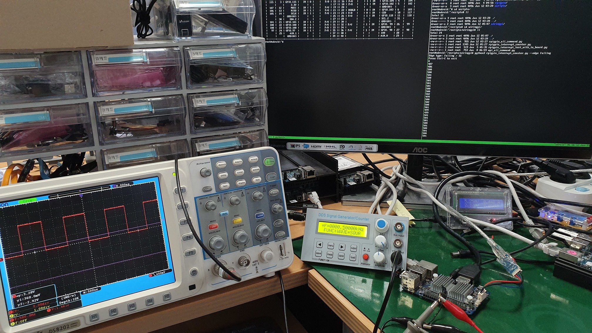
I set the Function generator up to generate a 1 KHz square wave, and checked that wave using an oscilloscope. I changed the amplitude for each target to 1.8V or 3.0V every time I changed the board. I then chose the pins, #22 for the interrupt source and #20 for ground. The physical pin #22 is equivalent to #25 in BCM numbering. All three models have the same form factor on the GPIO header. Finally, I wired the cables as shown in Figure 1.
Execution
Let's test with the C1+, first. Just run the script without any changes. As the script is, it should show numbers about 1000 every second since it is set to handle falling-edge interrupts and the function generator is set to generate 1 KHz square wave. To make sure, I also checked the current kernel version:
root@odroid:~# uname -a
Linux odroid 3.10.107-13 #2 SMP PREEMPT Wed Jun 19 02:31:43 -03 2019 armv7l armv7l armv7l GNU/Linux
root@odroid:~# python3 test.py
Press Ctrl-C to exit
1000
1003
1000
1000
1000
1001
1001
987
1001
1001
This shows the numbers as we expected. This couldn't be exactly 1000 in every moment, because there are many [un]foreseen factors which affect detecting interrupts. This is the output on the ODROID-C2:
root@odroid:~# uname -a
Linux odroid 3.16.68-41 #1 SMP PREEMPT Tue Jun 18 15:06:16 -03 2019 aarch64 aarch64 aarch64 GNU/Linux
root@odroid:~# python3 test.py
Press Ctrl-C to exit
981
993
993
984
985
996
977
995
1001
981
The following output is from the ODROID-XU4, which uses pin #26 for the interrupt source and #28 for ground:
root@odroid:~# uname -a
Linux odroid 4.14.120-160 #1 SMP PREEMPT Fri May 17 01:18:14 -03 2019 armv7l armv7l armv7l GNU/Linux
root@odroid:~# python3 test.py
Press Ctrl-C to exit
1005
1007
1014
1005
1008
1003
1005
1001
1005
1004
Finally, this is what it looks like on the ODROID-N2
root@odroid:~# uname -a
Linux odroid 4.9.182-31 #1 SMP PREEMPT Tue Jun 18 14:45:56 -03 2019 aarch64 aarch64 aarch64 GNU/Linux
root@odroid:~# python3 test.py
Press Ctrl-C to exit
1000
1002
1002
1003
1000
1000
1000
999
1000
1000
All the models work well on GPIO IRQ handling with RPi.GPIO. Note that the displayed number in the acceptable error range doesn’t matter, since it is continuously changed. Configure GPIO IRQ Edge Type We can also change the edge detecting type of the pin. There are three edge types:
- Falling
- Rising
- Both
This can be changed when you set GPIO IRQ handler in the code using GPIO.add_event_detect() function. These are respectively defined as:
GPIO.FALLING
GPIO.RISING
GPIO.BOTH
IUf you want to detect using the both-edge mode, replace existing IRQ_EDGE value in line #9 to the following one:
# From
IRQ_EDGE = GPIO.FALLING

# To
IRQ_EDGE = GPIO.BOTH
Here is a test to check if it works. With C1+, the modified script outputs like this with 1 KHz square wave.
root@odroid:~# python3 test.py
Press Ctrl-C to exit
1994
1997
1994
1998
1999
1980
2002
2001
2001
2002
It shows about 2000 because the handler reacts for both edge moments, which means it works flawlessly.
References https://sourceforge.net/projects/raspberry-gpio-python/
Be the first to comment