Building an ODROID GameStation Turbo (OGST) Case For Your ODROID-XU4
January 1, 2020By Brian ReeGaming, ODROID-XU4, Tinkering
The reason why we want to use the larger OGST case is because it comes with an expansion board that allows you to add power and reset buttons to the case and a place to hold an external USB harddrive. This will allow you to increase the available storage space on your harddrive size. This tutorial will show you how to quickly and easily assemble the case and secure the harddrive to the case. Needless to say, if you are building a retro gaming console this really opens up the door for storing a ton more games.
- Small Screwdriver Set
- Velcro® Strip Permanent or Removable Velcro Strip
- External USB 3 Hard-drive
Reviewing the Parts
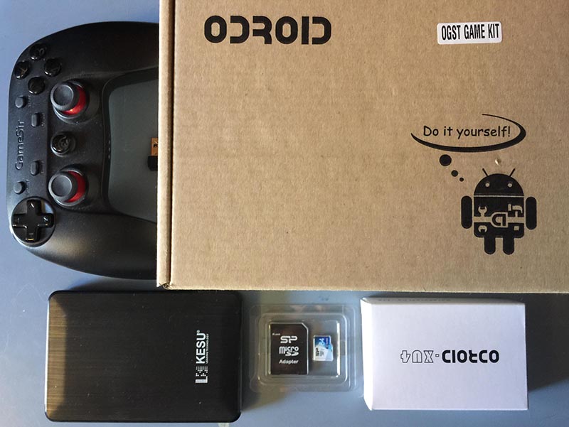
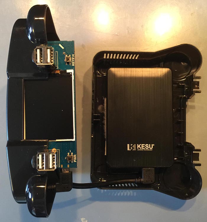
Let us take a look at the parts we will be working with. The following image shows the hardware needed for using the ODROID-XU4 with OGST as a retro gaming case.
Figure 1
The setup I will be working on, shown above, during this tutorial is an ODROID-XU4 running Lakka. You can actually use any setup you want on your ODROID-XU4. If you want more storage space then the OGST and this tutorial are for you. A wireless Game Sir controller. A 64GB micro SD for the boot drive. A KESU external USB 3 harddrive with 250GB of storage. Now I could have gone bigger but the drive is $40, so this is the perfect setup for the retro console builder on a budget. I will post some links for ODROID-XU4 building tutorials and parts below.
- Wired Game Sir Wired Controller (Hard Kernel) $17
- Wired Game Sir Wired Controller (Amazon) $17
- Wired Game Sir Wireless Controller $17
- KESU 250GB USB 3 External Hard-drive $37
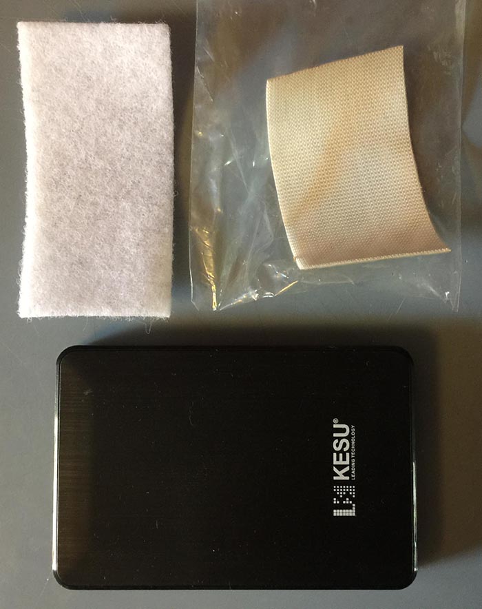
Now to hold the drive securely in the case we need some Velcro® strips. This will give us a secure but easily detachable way to store the harddrive in the case. You have two options, super strong permanent strips or strong but removable strips. If you want to potentially reuse the hard-drive without having Velcro strips on it, then you might want to go for the second option. Here are the links for the two types of strips.
Once you have got that all sorted out you will be ready to build your advanced case. Remember you can always go bigger on the harddrive. As long as it has a similar size to the link provided above it will fit in the case fine. I chose to use the super strong version of the Velcro tape because I wanted the drive to be firmly held in place and have very little chance of coming off. I also do not intend to use the harddrive for something else as it was purchased solely for this console project. Next let us open up our OGST case and see what is inside.
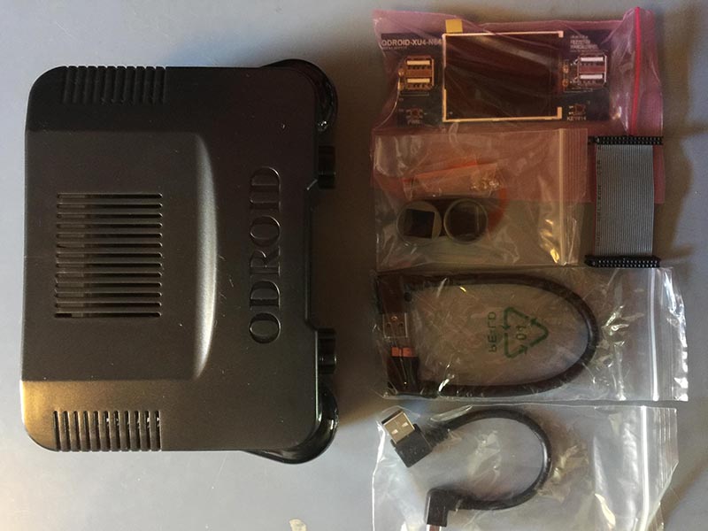
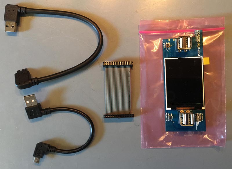
Figure 3
In the case you will find an expansion board with a small screen. A set of plastic caps, a ribbon cable, 2 USB cables, and some screws; oh and, of course, a case. The cables are important! They USB A to USB Micro B cable is perfect for the external USB drive. 7 It has a 90 degree connector that will make it much, much easier to house the drive in the OGST case. Let us take a look at our ODROID-XU4 hardware.
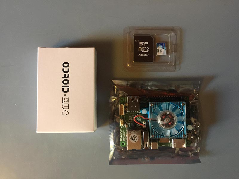
Figure 4
Again, we are using the ODROID-XU4 with a 64GB micro SD card. You will need a screwdriver at this point. A standard electronics screwdriver set should do the trick. Now if you do not know how to setup your ODROID-XU4 with an OS you can follow the links below.
- Munku R3/ODROID-XU4 Ubuntu with Retroarch Multi-use Console - Tutorial Part 1 - Munku R3/ODROID-XU4 Lakka Retro Gaming Console - Tutorial Part 1
From this point on, I will assume you have your ODROID-XU4 device all setup. Because I am building this case for a retro gaming console and I want to use every last drop of the device's resources for emulation I decided not to setup the second screen on the expansion board. If you want to set yours up, this may depend on the OS you are using on your device. You can find more information at these links:
- OGST Case Second Screen Info (https://bit.ly/2tdvwTl)
- OGST Case Second Screen Info (https://bit.ly/2MCbNDP)
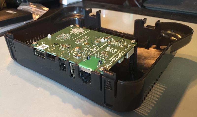
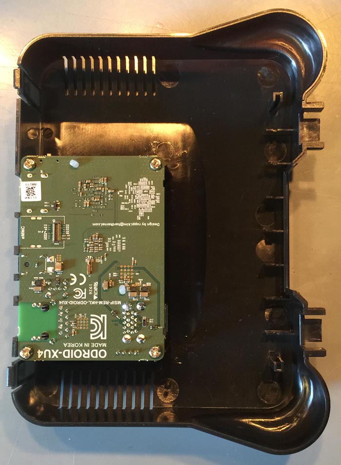
Prepping The Case Top
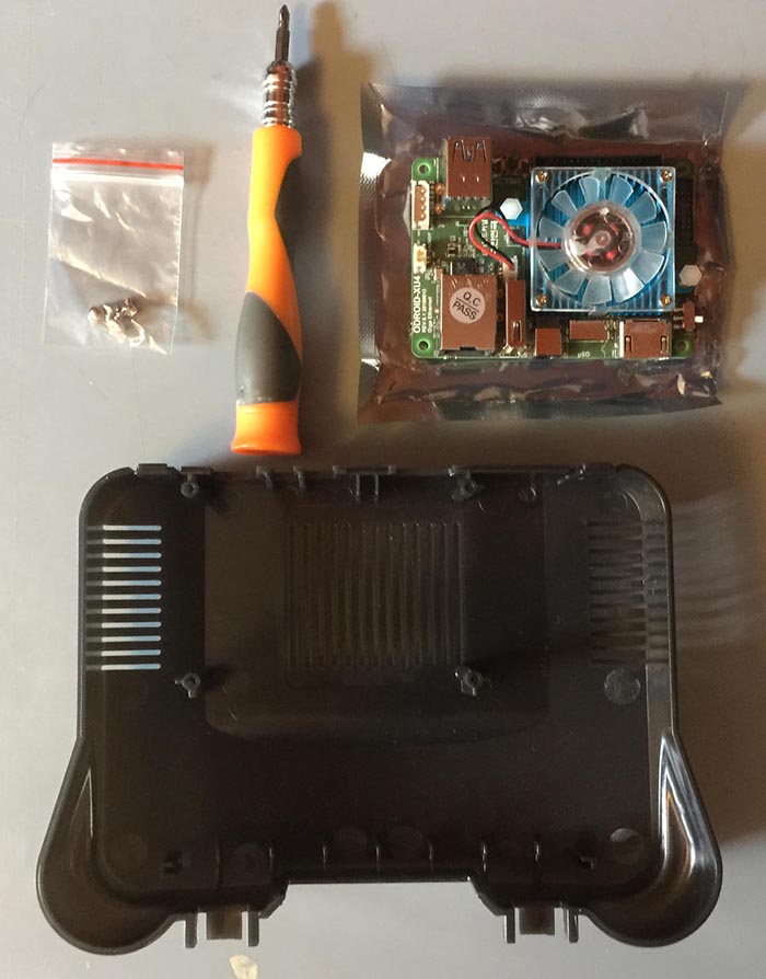
The board mounts upside down on the top side of the case. This is perhaps a bit unusual but as you will soon see the case is wonderfully designed and very easy to use. The two pictures below depict the mounted ODROID-XU4 board on the top side of the OGST case. TIP: Take your time with the screws. The fit is a little strange due to the larger threading on the screws. Just take your time and carefully tighten them until the board is secure. Try not to over tighten them. The picture shows the ODROID-XU4 board, screws, case top, and the screwdriver I am using.
Figure 5
The following pictures depict the board in position and properly screwed into the case top.
Figure 6
Figure 7
Next up we will be setting up the expansion board and ribbon cable. The picture below depicts the parts you will need for this step.
Figure 8
We want to connect the ribbon cable to the mounted board first. Make sure you have the direction marker facing the correct way. The marker requires a slot in the ribbon cable connector. Line up the slot on the ribbon cable connector with the mark on the cable itself. Carefully make sure that the ribbon cable is all the way into the connector. You may need to take your time and push it down evenly. TIP: Do not put too much pressure on the board when you are attaching the ribbon cable.
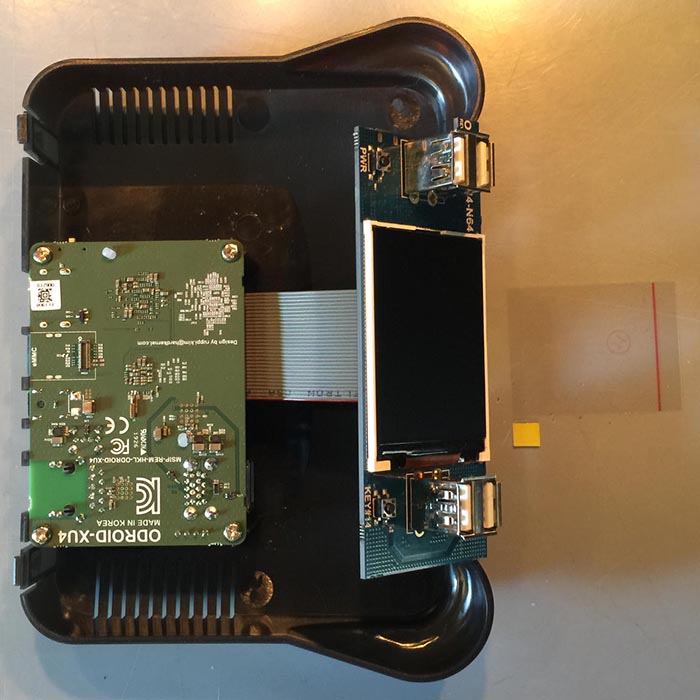
Next you will want to attach the expansion board. Again make sure the ribbon cable mark is properly aligned with the slot on the ribbon cable connector. Be extra careful when attaching the ribbon cable to the expansion board as it is very easy to end up pressing on the screen and potentially cracking it. After the ribbon is connected take off the screen protection sticker and let the screen sit in the two guide slots built into the case as shown below. Do not push it all the way into the case top just yet.
Figure 9
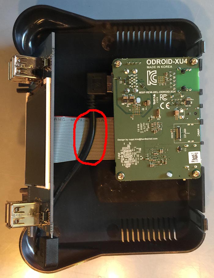
Now we want to connect the USB-to-USB cable. This splits one USB port on the ODROID-XU4 board into 4 USB ports that are available on the front of the OGST case. Notice that we want the USB cable to sit on top of the ribbon cable as shown below. We are working on the top of the case so everything we are doing will be flipped upside down when we are done. The USB cable should be below the ribbon cable this will make it easier to access in case you want to take apart the case.
Figure 10
Finishing Up
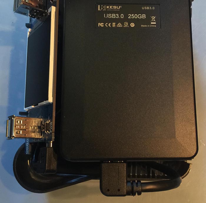
Now we are going to prepare the harddrive. Holding the harddrive upside down use the included drive USB cable to connect the harddrive to the expansion board. Notice that we are bending the cable and sort of visualizing how the harddrive will sit in the case. This is a good time to make sure that the drive can fit and that the cables all behave nicely. Take a look at the picture below. In this shot I'm double checking how the cable works with the drive's cable connection. It looks like it will play nicely with the case.
Figure 11
Figure 12
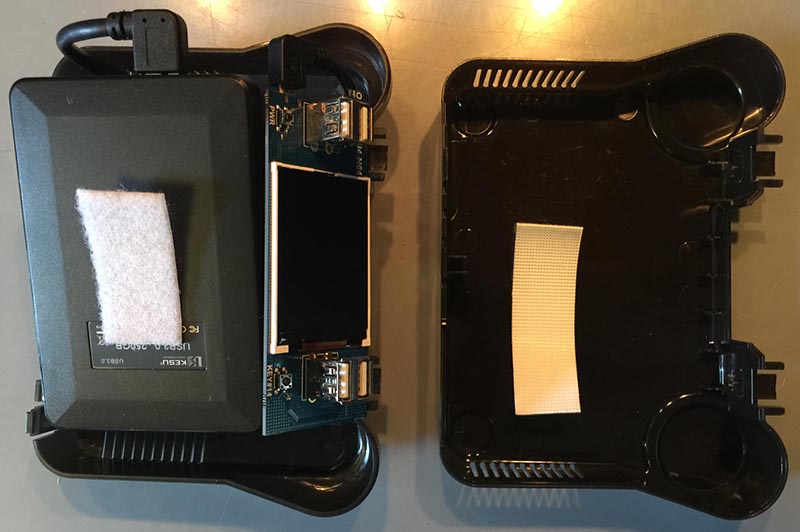
Ok, so we still have not put anything together yet. We need to do a little more work to make sure the drive sits on the bottom of the case properly. While leaving the top of the case as is, put the bottom of the case next to it and place, but do not adhere, the Velcro strips where you want them. I usually put the loop part on the drive. You can set it up any way you like. If you use wider strips the hold will be stronger and you will have more flexibility in how you place the harddrive on the bottom of the case. The photo below shows my first attempt at placing the velcro strips. I eventually doubled up on the strips to make the contact surface bigger. TIP: Make sure that the drive's cable is taken into account when setting up the Velcro strips on the case bottom.
Figure 13
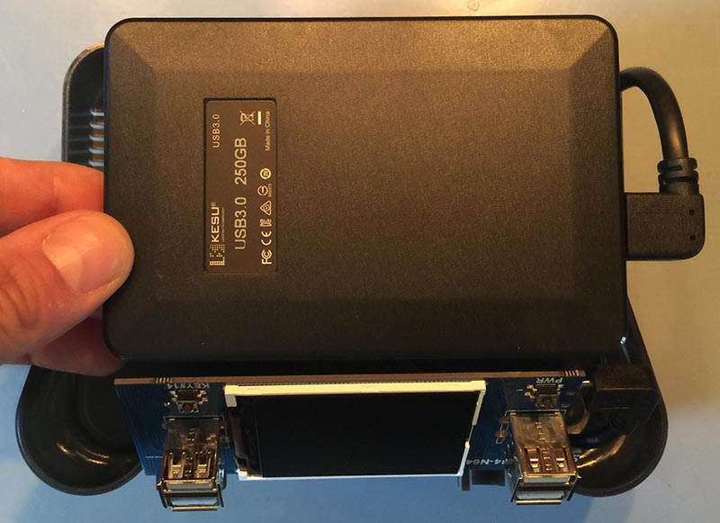
Next up you will want to set the expansion board firmly in place. Be careful to make sure it goes in evenly. If one side is farther down the plastic guides you will not be able to seat the board properly. Resist the urge to apply a lot of pressure during this step. Just apply enough force to get it set properly. Now you can place the top of the case vertically on your work surface and place the drive and the bottom part of the case next to it with the USB drive cable attached as shown below. This should be the final check before we begin to close up the case.
Figure 14
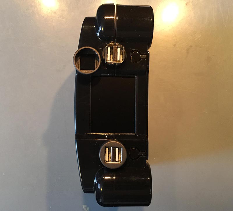
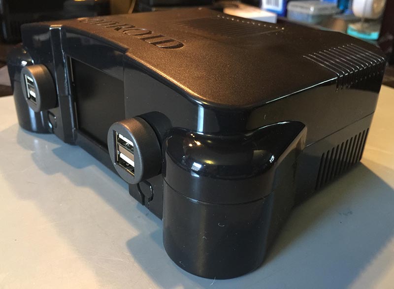
Finally, it is time to close the case! Bring the two sides together. Make sure the USB cables are below the expansion board's ribbon cable. Make sure the harddrive's USB cable is looped and set properly and that the drive is secured with Velcro strips. Close the case and put the two grey plastic caps over the front USB ports. TIP: Make sure to align the two small ridges on one side of the cap. These line up with small ridges on the case itself.
Figure 15
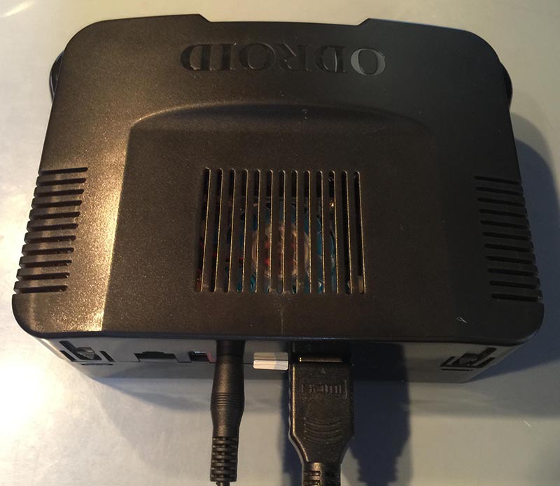
Congratulations! You are done. You have now added larger drive storage to your ODROID-XU4 build! The pictures below depict the completed setup. Enjoy!
Retro ESP32: The Ultimate Emulation Image for Your ODROID-GO
January 1, 2020By @32teethGaming, ODROID-GO
Retro ESP32 is the ultimate feature-packed launcher for the ODROID-GO. The launcher includes color schemes and theming by drawing inspiration from the popular RetroArch emulator front end. We packed 11, at the time of publication, pre-bundled emulators including ROM / Game manager. Additionally, each emulator includes an in game menu for further ROM management.
Figure 1 - ESP32 Launch in action on the ODROID-GO
Installation
Installation of Retro ESP32 was made to be very simple.
Sit back and relax while your ODROID-GO flashes the new firmware
Supported Emulators
Retro ESP32 supports a wide range of emulators for you to play on the ODROID-GO. Below is a list of all the support emulators:
Nintendo Entertainment System
Nintendo Game Boy
Nintendo Game Boy Color
Sega Master System
Sega Game Gear
Colecovision
Sinclair Zx Spectrum 48k
Atari 2600
Atari 7800
Atari Lynx
PC Engine
How To Configure And Use The CAN Bus: Using the ODROID-N2 With Microcontrollers
January 1, 2020By Justin Lee, CEO of HardkernelODROID-N2, Tinkering, Tutorial
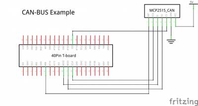
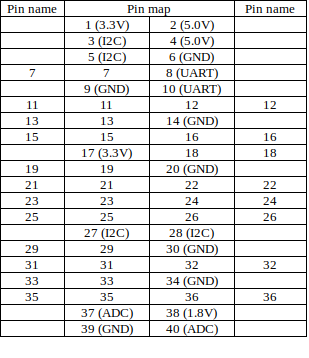
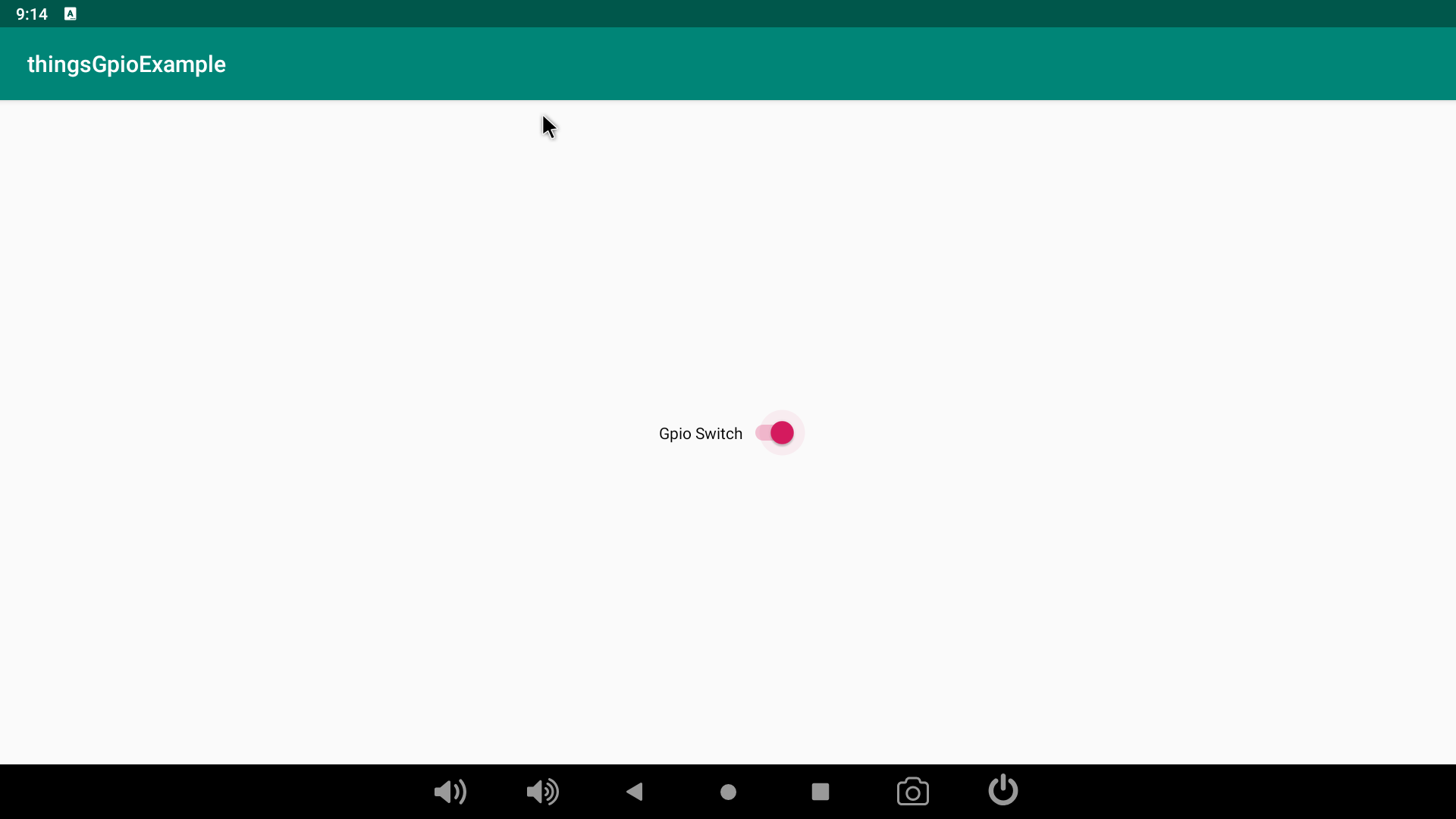
This article explains how to enable the CAN bus on ODROID-N2 via HW SPI interface. The detailed instructions to acquire data via a MCP2515 Bus Monitor board are documented here, as well.
Fig. 01
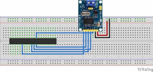
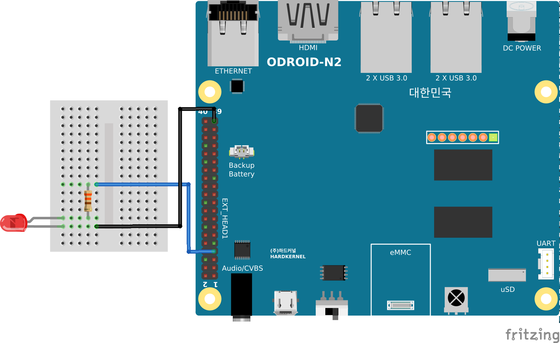
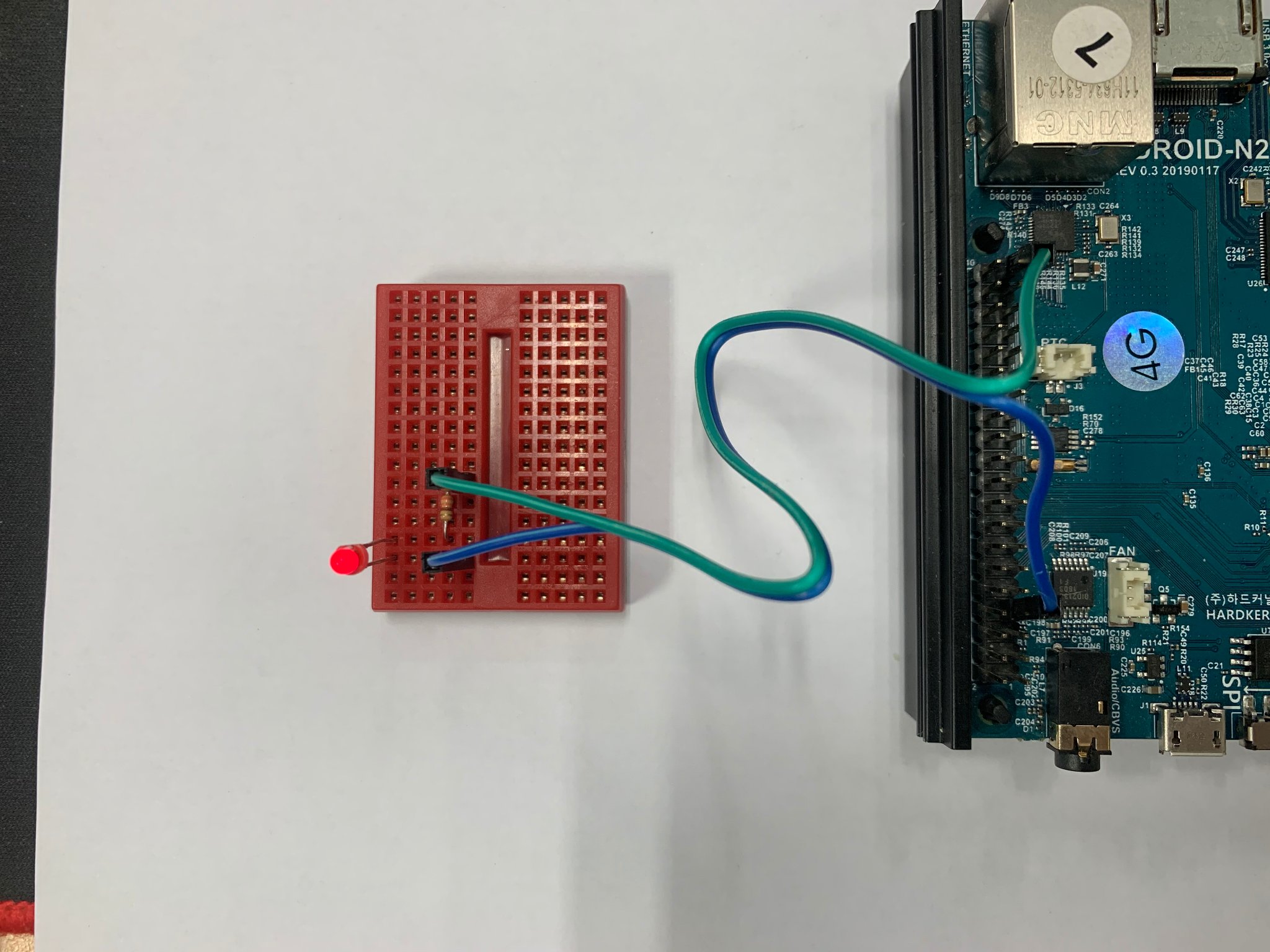
H/W connection
The following products are required to configure the hardware:
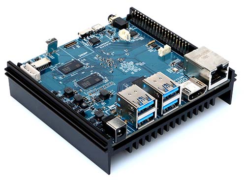
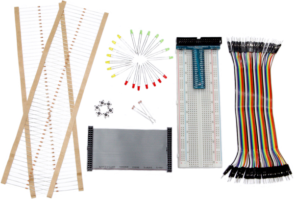
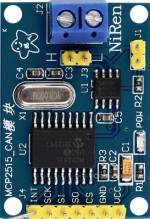
ODROID-N2
Tinkering kit
MCP2515 CAN module
Fig. 02
Fig. 03
Fig. 04
Reference circuit
Fig. 05
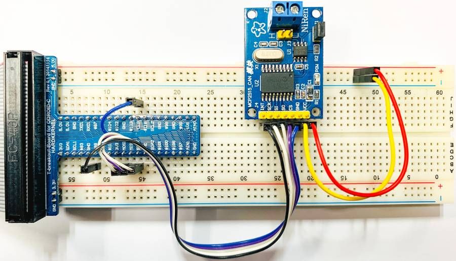
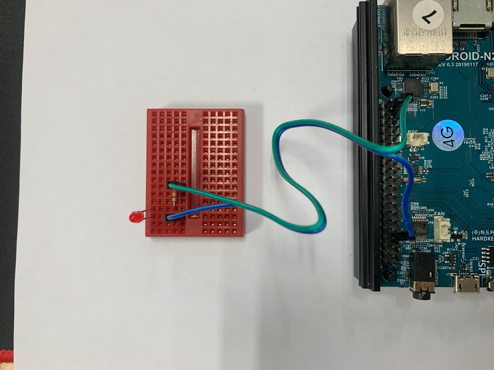
With tinkering kit
Fig. 06
Fig. 07
Software installation
Note:
Operation confirmed with ODROID-N2 Ubuntu minimal image on 4.9.205-64 kernel.
The can-bus example uses the same cs-pin as spidev, so both must not be enabled at the same time.
If spidev is enabled, the can-bus may not work properly.
Updating of the kernel is highly recommended. This is available with Linux odroid 4.9.205-64 or higher version
root@odroid:~# apt update && apt full-upgrade
Enable the modules using **device-tree-compiler**
root@odroid:~# apt install device-tree-compiler
Change the status to **okay** on the SPI nodes of the device tree.
# SPICC0
root@odroid:~# fdtput -t s /media/boot/meson64_odroidn2.dtb
                 /soc/cbus@ffd00000/spi@13000
[status okay
root@odroid:~#
# can0
root@odroid:~# fdtput -t s /media/boot/meson64_odroidn2.dtb
                 /soc/cbus@ffd00000/spi@13000/can@0
status okay
root@odroid:~#
Check if the status changed.
# SPICC0
root@odroid:~# fdtget /media/boot/meson64_odroidn2.dtb
                 /soc/cbus@ffd00000/spi@13000
Status okay
root@odroid:~#
# can0
root@odroid:~# fdtget /media/boot/meson64_odroidn2.dtb
                 /soc/cbus@ffd00000/spi@13000/can@0
Status okay
root@odroid:~#
Then reboot to apply the changes. you can also check if the modules were correctly loaded.
The can-utils package is a collection of CAN drivers and networking tools for Linux. It allows interfacing with CAN bus devices in a similar fashion as other network devices.
sudo apt install can-utils
We need to perform the Loopback test on a single CAN port. Set loopback mode on can0
ifconfig can0 down
ip link set can0 type can bitrate 125000 loopback on
ifconfig can0 up
ip -details link show can0

root@odroid:~# ifconfig can0 down
root@odroid:~# ip link set can0 type can bitrate 125000 loopback on
root@odroid:~# ifconfig can0 up
root@odroid:~# ip -details link show can0
3: can0: <NOARP,UP,LOWER_UP,ECHO> mtu 16 qdisc fq_codel state UNKNOWN mode DEFAULT group default qlen 10
  link/can  promiscuity 0
  can <LOOPBACK,TRIPLE-SAMPLING> state ERROR-ACTIVE restart-ms 0
        bitrate 125000 sample-point 0.850
        tq 400 prop-seg 8 phase-seg1 8 phase-seg2 3 sjw 1
        mcp251x: tseg1 3..16 tseg2 2..8 sjw 1..4 brp 1..64 brp-inc 1
        clock 5000000numtxqueues 1 numrxqueues 1 gso_max_size 65536 gso_max_segs 65535
root@odroid:~#
The following command shows the received message from the CAN bus
candump can0
On a second terminal, The following command sends 3 bytes on the bus (0x11, 0x22, 0x33) with the identifier 500.
cansend can0 500#11.22.33
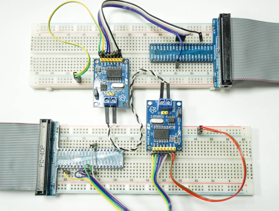
How to test CAN-bus link between 2 ODROID-N2 boards
Connect CANL, CANH pins between two ODROID-N2 boards
Fig. 08
Power-up both boards and type the following into the shell of both boards for configuring the CAN bus device:
ip link set can0 type can bitrate 125000 triple-sampling on
ifconfig can0 up
Type the following into the shell of board 1 (which is used for testing/receiving over the can0 device):
candump can0
Type the following into the shell of board 2 (which is used for testing/sending data packets over the can0 device):
cansend can0 500#11.22.33
At this point, board 1 will receive the data packet sent from board 2:
ODROID-GO Advance: The Newest Generation of Hardkernel’s Most Popular Handheld Computer
January 1, 2020By Justin Lee, CEO of HardkernelGaming, ODROID-GO Advance, ODROID-GO
We announced the ODROID-GO in 2018 June to celebrate our 10th birthday. It was amazing and fun to be able to emulate old-school 8-bit retro games with more than expected performance with only the MCU, rather than a high-end MPU. The device has been very popular not only for gaming but also for education.
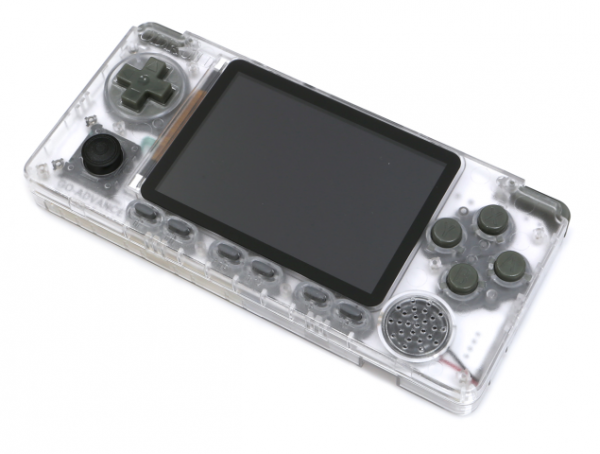
Figure 1 - ODROID-GO Advance
Figure 2 - ODROID-GO Advance
We continued to hear from users who wanted to play 16-bit or 32-bit retro games on a handheld device with more advanced features and capabilities. Therefore, we researched a new platform this year and found a suitable solution, so we've spent several months developing a new 64-bit Linux-powered device. This new device, called the ODROID-GO Advance, has a modern 64bit ARM low-power quad-core processor as well as wide-viewing-angle 3.5inch LCD.
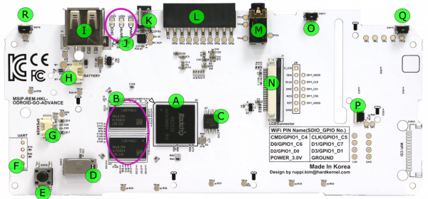
ODROID-GO Advanced specifications
Processor
CPU : RockChip RK3326(Quad-Core ARM Cortex-A35 1.3GHz)
GPU : Mali-G31 Dvalin
A CPU : Rockchip RK3326
B RAM : 1GB DDR3L
C SPI Flash(16Mbytes Boot)
D MicroSD card slot
E Forced SD card boot(without spirom)
F UART port(But not mounted default)
G Speaker connector
H Battery connector
I USB 2.0 type-A Host
J Statue LED(charger, alive, power)
K DC Power Jack
L 10pin expansion port
M Audio jack
N 20pin LCD connector
O PWR switch
P Analog joystick connector
Q Left trigger button
R Right trigger button
How to use it
The following links provide information on how to to use the ODROID-GO Advance:
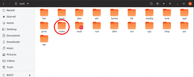
Transferring game roms via SD card reader (Linux HOST-PC)
Insert your SD card which you have installed to your HOST-PC and then copy game ROMs to /roms folder, as shown in Figure 5.. You can copy your game ROMs into the /roms folder without any permission.
Figure 5 - The ODROID-GO Advance /roms folder
Since the SD card data partition file system is EXT4, you can't access it from a Windows PC, so we need to prepare a way to transfer ROM files from a USB storage on the system. First of all, you can check your network environment. If you have any USB network module, follow this instructions at Connecting your GO-Advance to an wireless network with an extra USB WiFi adapter. Compatible WiFi dongles are sold separately (WiFi module 0, WiFi module 3, WiFi module 5A)
After that, you can send your game ROMs to the GO-Advance with the “scp” command on your HOST-PC:
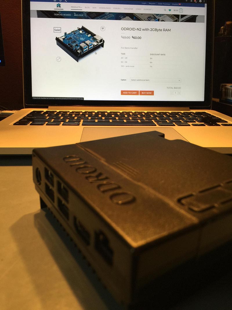
Monku R4 With An ODROID-N2 and Batocera Linux: The Best Retro Gaming Console You Can Build for Around $100
January 1, 2020By Brian ReeGaming, ODROID-N2, Tutorial
Before we begin you need to gather the following items. All these items can be ordered from Hardkernel:
- ODROID-N2 (2GB of RAM)
- ODROID-N2 Case
- 64GB Micro SD Card x2
- HDMI Cable x1
- Power Supply 12V/2A x1
- GameSir Wired Controller x1
- A 16GB or 32GB eMMC Memory Module
- A Micro SD to USB Adapter
- An eMMC to Micro SD Adapter
Introduction and Tutorial Goals
This tutorial covers the process of setting up an ODROID-N2 with 2GB of RAM and iInstalling Batocera Linux so we can use our ODROID-N2 as a TV retro gaming console. I lovingly call this device the Monku R4. I will cover setting up the operating system, setting up the ROMs and BIOS files, and I'll cover getting box art and screenshots for your ROMs. In my opinion this is the BEST retro gaming console you can build for your money. It runs a ton of emulators and it runs them all very well. Let's take a look at some of the emulators it will run. I've personally set one up to run the following emulators.
Atari 2600
Atari 5200
Atari 7800
C64
Colecovision
DOOM
Dreamcast
FBA MAME
Game Boy
Game Boy Advance
Game Boy Color
Intellivision
Jaguar
Lynx
Magnavox Odyssey
MAME
MS-DOS
MSX 1/2
N64
NES
NEO-GEO Pocket
NEO-GEO Pocket Color
PSP
PS1
ScummVM
Sega 32X
Sega CD
Sega GameGear
Sega Genesis
Sega Master System
Sega SG-1000
SNES
Turbo Grafx 16
Turbo Grafx 16 CD
Virtual Boy
WonderSwan
WonderSwan Color
ZX Spectrum
A note about cost: I say in the title that this is the best retro gaming console you can build for under $100, however, you would have to get only one 64GB SD card, and the smaller eMMC module to keep the price around $100. I do recommend getting the dual pack of 64GB SD cards because you can make a backup.
Now that you have an idea of what you're working with, and just to be clear the ODROID-N2 is much more powerful than the ODROID-XU4 (Sorry ODROID-XU4 fans), I'm tailoring this tutorial to use an eMMC module as the bootable OS drive to get even more performance out of the ODROID-N2. You can decide to run things entirely off a micro SD card or a larger eMMC module, if you see fit. I won't cover these in detail but you can take different parts of the tutorial and apply them to an SD-card-only or eMMC-only implementation. The separation we have between the OS and the ROMs allows us to keep the SD card separate from the OS and on a Fat32 filesystem. This means we can pop out the SD card and plug it into any computer and edit it, as needed. It is a bit more difficult to do the same thing with a bootable ext4 Linux filesystem for the Mac OS or Windows PC.
TIP: If you are opting for a single storage install, only eMMC or only SD, then you will most likely have to login to your device via SSH at some point in the setup process to configure it. The default root password for the device is Linux.
Setting Up the eMMC Module
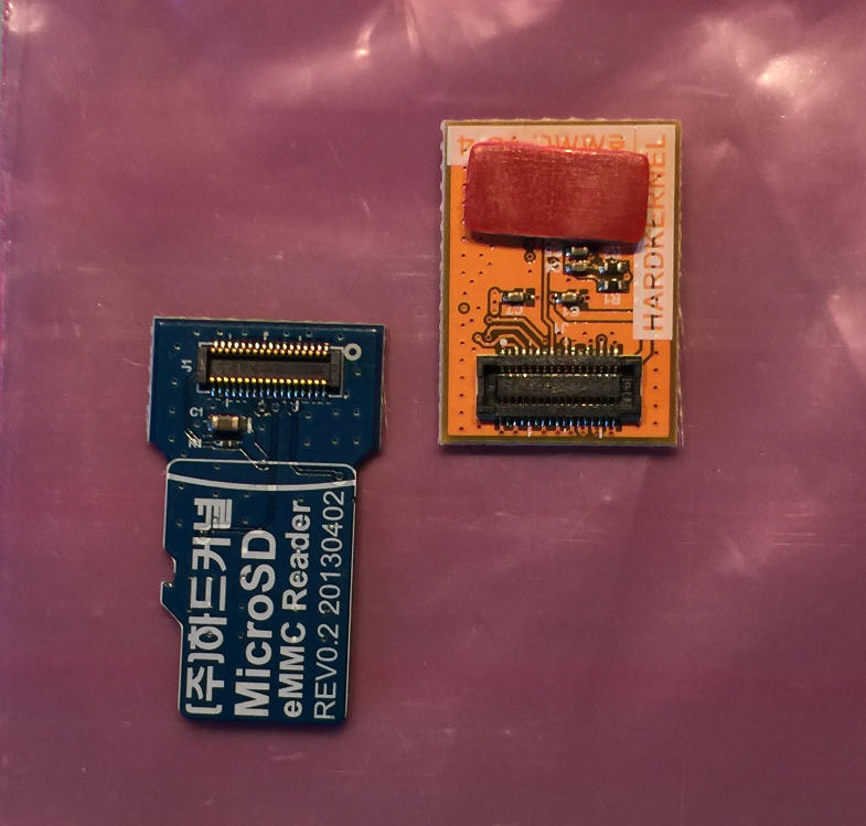
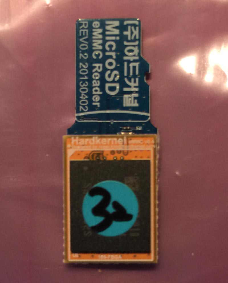
Let's take a look at the hardware we'll need to write to the eMMC module. Below is a picture of the eMMC to micro SD adapter. Below that is a picture of the adapter and the eMMC module. I'll be using a 32GB module, but you really only need a 16GB module because we're going to use it to house the OS. If you want to perform a more advanced setup with ROMs in multiple locations, eMMC and SD, then you'll probably want a 32GB or larger eMMC.
Figure 1 - eMMC module and SD adapter
Figure 2 - eMMC module mounted in the SD card adapter
If you are new to eMMC modules I recommend going through the following tutorial as I'll only cover the image writing process here and not any eMMC specific steps.
You'll want to get a copy of the latest version of Batocera Linux for the ODROID-N2. Batocera Linux is based on Recalbox Linux so if you're familiar with RecalBox then you are ahead of the game. Use the links below to locate the latest version of Batocera Linux for the ODROID-N2 and download it.
TIP: While this tutorial focuses on the ODROID-N2 you can use it as a general guide for installing Batocera Linux on other hardware like the ODROID-XU4.
Once you've got your image ready it's time to get some software that you can use to flash the eMMC module. If you are using a Mac I recommend getting Balena Etcher. It works great and I highly recommend it. If you're using Windows you can grab a copy of Win32 Disk Imager. Though not as pretty as Balena Etcher, Win32 Disk Imager gets the job done.
For Linux users you'll have to perform the following steps. Don't worry it's not too bad.
1. Insert your SD card into your computer.
2. Locate the device, by running sudo fdisk -l. It will probably be the only disk about the right size. Note down the device name; let us suppose it is /dev/sdx. If you are in any doubt, remove the card, run sudo fdisk -l again and note down what disks are there. Insert the SD card again, run sudo fdisk -l and it is the new disk.
3. Unmount the partitions by running sudo umount /dev/sdx*. It may give an error saying the disk isn't mounted - that's fine. Copy the contents of the image file onto the SD card by running
Of course, you'll need to change the name of the image file, as appropriate. You'll also need to adjust the destination argument, of, to match the target device in your environment.
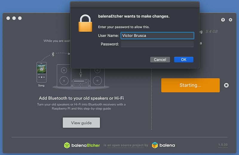
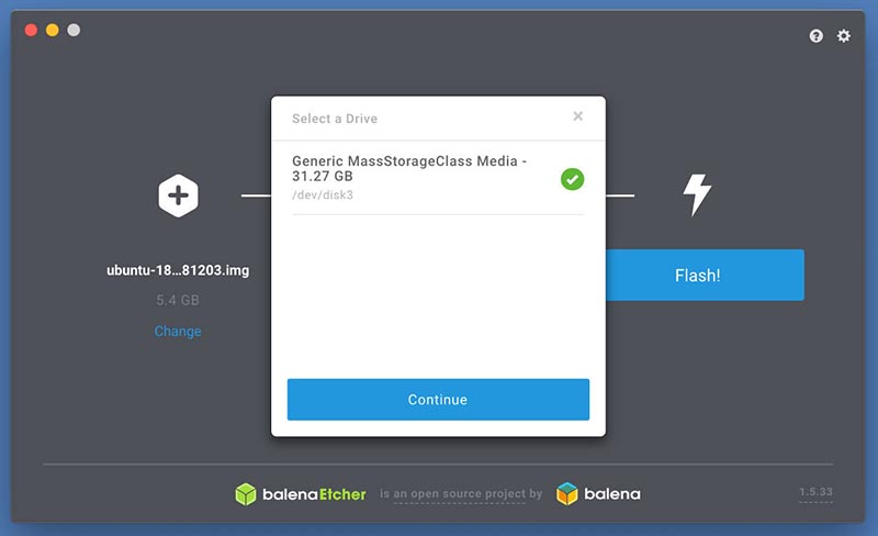
ALERT: Ensure the drive, device, drive letter you are flashing are correct. Make sure you are not overwriting another important drive! I'll include images of the process as it looks on Mac. You may be prompted to gain admin privileges on Mac and Windows.
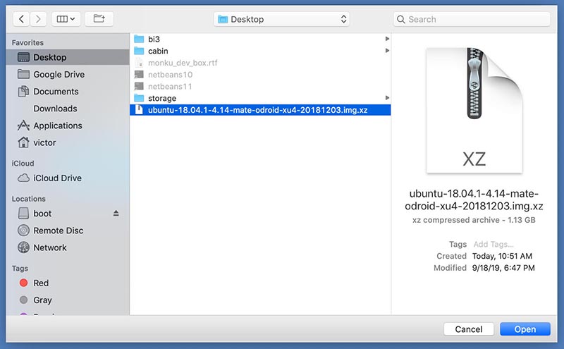
Select the image file that you want to flash to the eMMC module. The image file depicted below is not the file you'll be using for this tutorial. You'll be using your Batocera Linux ODROID-N2 image file.
Figure 3 - The compressed image file
Figure 4 - Answer any prompts for admin privilege
Figure 5 - Double check that you're indeed flashing the correct device and that it is the correct approximate size.
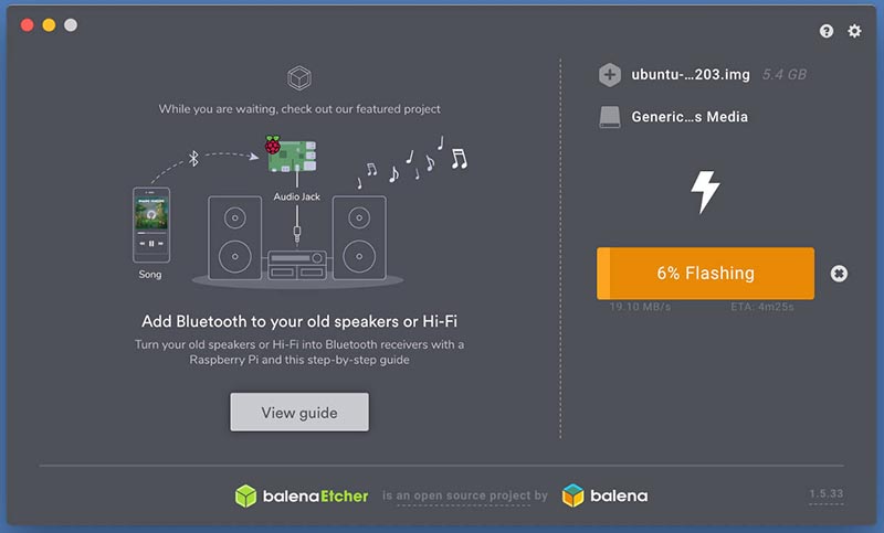
Figure 6 - Start flashing the device and wait for the process to complete.
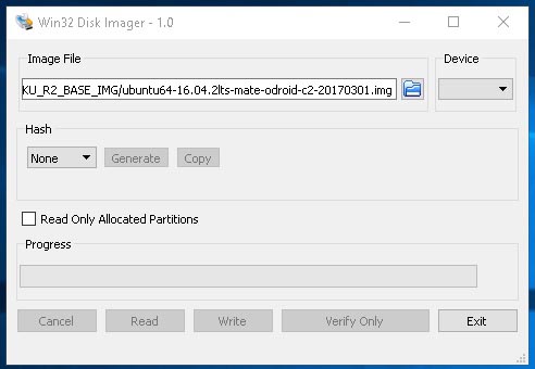
On a Windows PC, if you're using the software tool listed above, you would see something like the following before clicking the Write button. Again wait for the tool to finish writing the image to the eMMC module. Also, the image file depicted below is not the file you'll be using for this tutorial. You'll be using your Batocera Linux ODROID-N2 image file.
ALERT: Make sure that you choose the correct drive letter. Triple check the letter so you don't overwrite another important drive!!
Figure 7 - Win32 Disk Imager
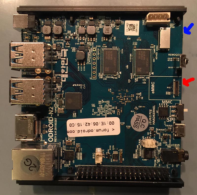
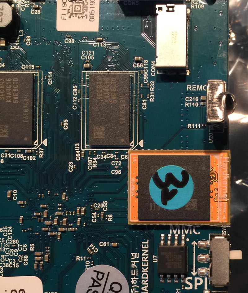
Next let's boot up the device and test out the OS. The image below shows the ODROID-N2 with a red arrow next to the eMMC module slot and a blue arrow next to the SD card slot. If you're going the micro SD card route you'll need to remove the card while setting up the case.
Figure 8 - eMMC in red, and SD Card is blue
Connect the eMMC module to the ODROID-N2 as shown below and prepare a static free surface for the device. You'll want to get your 12V/2A power supply ready.
Figure 9 - 32GB eMMC module loaded onto N2
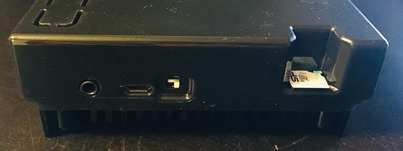
Make sure you have the white switch on the back of the ODROID-N2 pushed all the way to the right to boot off of the eMMC module. Push it all the way to the left to boot off of the micro SD card. In our case we'll be going with pushing it to the right to boot off of the eMMC module. We'll still be able to access the micro SD card as a drive.
Figure 10 - white switch is set to the right, and SD card is inserted
Plug in the power supply, plug in the HDMI cable, hold your breath and with any luck you'll be looking at a screen similar to the one depicted below. Nice!
Figure 11 - Menu up and running
Turn off the ODROID-N2 by exiting out of the device using a keyboard. Or, if you have your game controller handy you can configure it via the Batocera Linux UI and then power down the device. I'll be covering how to configure things in detail in just a bit. That brings us to the end of this section of the tutorial next up we'll be setting up the case and then moving on to some configuration and customization topics.
Putting Together the Case
The case is actually ingeniously designed as you'll come to see. One thing that is cool is that the whole thing rests on a heat sink. That's right, the bottom of the N2 is a big heatsink but it also acts as a really solid base for the device. TIP: Use black electrical tape and place 4 pieces on the base of the ODROID-N2's heatsink, the two main pieces of metal that actually touch the surface it's resting on. Place one piece near each of the four corners. This will create a softer contact with different surfaces and also prevents sliding. Lay out the ODROID-N2 and the parts of the case as shown below.
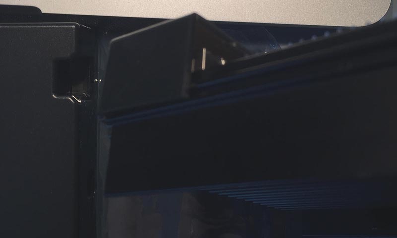
There is a little ridge on the left and right edge of the ODROID-N2, take the smaller case top - the one on the left in the image above - and slide it onto the ODROID-N2 being careful to keep it on the guide ridges. The image below shows the smaller front part of the case in position and the guide ridges.
Figure 12 - little ridge on the left and right edge of the N2
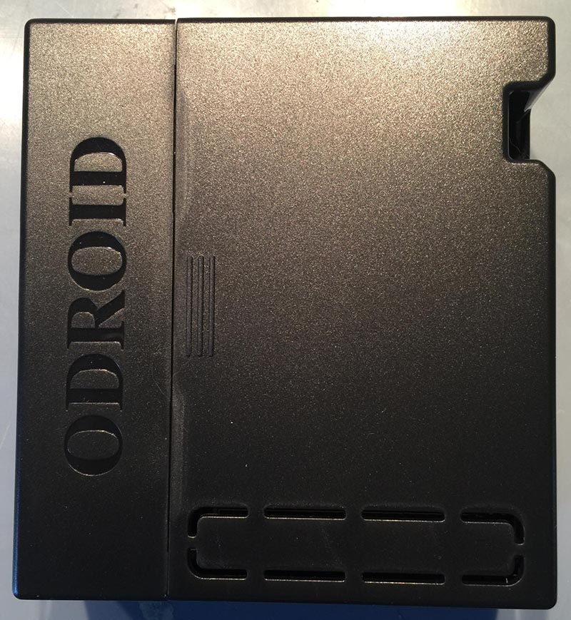
Next slide in the larger case top till the two meet. Make sure to keep it straight while pushing it gently along the guide ridges. The two case top pieces will meet and click together with a small clasp. Viola, the case is done!
Figure 13 - Finished case
Figure 14 - Glamour shot
Case closed, lol. Ok so now that we have the ODROID-N2 properly housed and protected, replace your SD card, if you're using that method, in the slot on the back of the case. Boot up the device one more time to make sure everything is in order. That brings us to the end of this section. Next up we're going to work on configuring our micro SD card as an external filesystem that Batocera Linux uses for accessing ROMs. I'll also cover setting up controllers, advanced Batocera Linux configuration options, and grabbing ROM box art in this tutorial.
Configuring the Controller and Micro SD Card
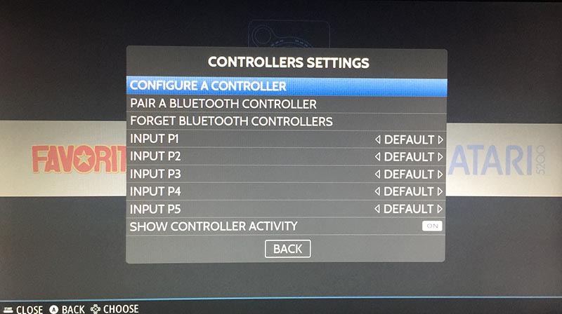
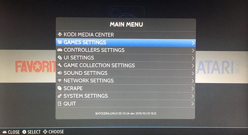
First let's get the controller configured. If your controller isn't working the way you expect, you can use a USB keyboard to navigate the main menu. Try pressing the start button or equivalent on your controller this will bring up the main menu. You can also use a keyboard and press the spacebar to bring up the main menu. The GameSir controller we recommend here has a start button. You should see something similar to what's depicted in the image below. Select the Controller Settings menu option.
TIP: If you are using a keyboard to navigate the menu system, the enter key is used to make selections, the esc key is used to go back to a previous menu, and the space bar is used to close/open the menu system.
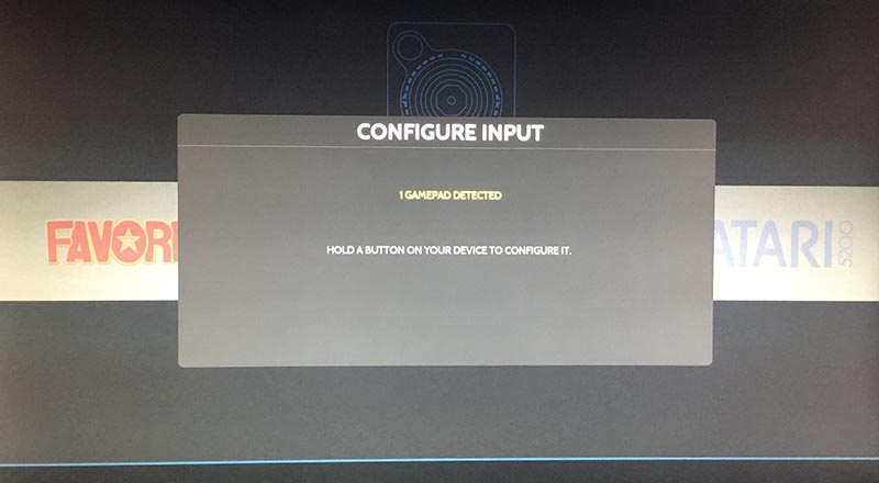
Next you'll want to select the Configure a Controller menu option. Selecting this option will bring up a controller configuration screen. You can exit this screen by hitting the start button or the space bar a second time if you already have your controller configured or you accidentally selected this option again after configuration. You will be prompted to hit certain buttons on the controller in series and then you're all set. That's it. It's very easy to do. Below is a picture of the controller configuration prompt. TIP: Pressing the blue GameSir controller button and the start button at the same time will exit out of the current running emulator. You may need to configure this differently for different controllers. TIP: If your wired GameSir controller isn't being recognized by the system hold the blue button down for a few seconds until the little red square on the front of the controller moves over to the second position. If it still isn't recognized try position three, then position four.
Figure 15
Figure 16
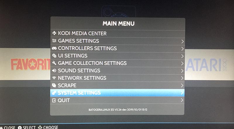
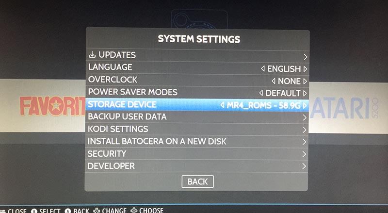
Next thing we're going to do is setup the micro SD card to work with Batocera Linux. I recommend using a 64GB card and getting a pack of two. There are links above for the ones I use. They are affordable and reliable. Plug in the micro SD card and then bring up the main menu using the start button or space bar. Select the System Settings options as depicted below.
Figure 17 - Navigate down to the Storage Device menu option as depicted below.
Figure 18
This will bring up a selection box that lets you choose from a few different storage locations. Pick the entry that has the same name as the micro SD card you put into the ODROID-N2. The system will now reboot after you select the drive. During this reboot Batocera Linux will create, on your micro SD card, a new filesystem that will hold all the ROMs, BIOS files, and configurations for the emulators you want to set up.
That brings us to the conclusion of this section of the tutorial. We now have a bootable version of Batocera Linux running on our ODROID-N2 device. We have a configured game controller, and we know how to navigate the menu system. We also have an external file system, our micro SD card, prepped and ready for ROMs and BIOS files.
Adding ROMs and BIOS Files
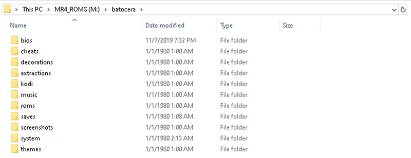
Now we are ready to add ROMs and BIOS files to the micro SD card that we set up with the Batocera Linux external filesystem in the last section of the tutorial. You will need an adapter to connect the micro SD card to your PC or Mac so that you can copy and paste the files into the proper directory. Below is a picture of the contents of the root folder which is named batocera.
Figure 19
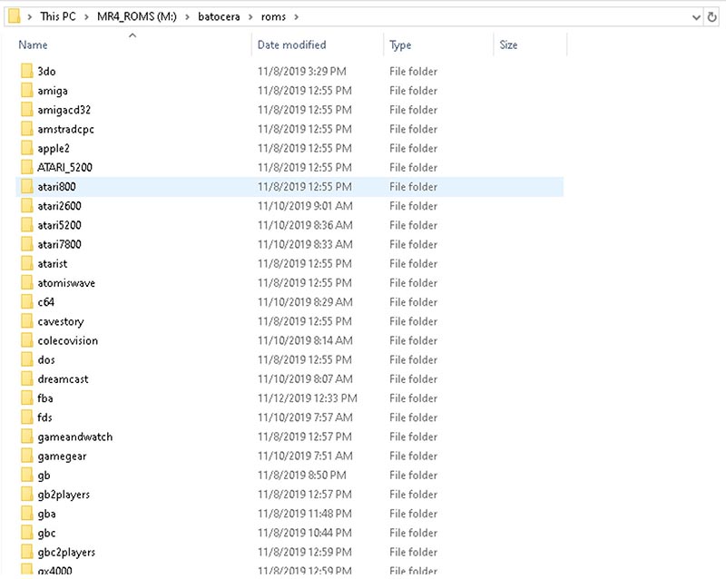
Notice that you have some other options to use on your Batocera Linux device like Kodi for music and videos. For our purposes though we're mostly concerned with the ROMs folder. Open up the ROMs folder and you will see a directory for each supported system. Now I'm not 100% sure if every emulator runs on every piece of hardware that Batocera Linux can be installed on but certainly all the best ones do. Copy and paste your ROMs into their corresponding directory. If you have a question about where to place ROMs for a certain system just look it up online and you should be able to locate the proper folder. You can also read the _info.txt file in each ROM folder to see what system it supports.
Figure 20
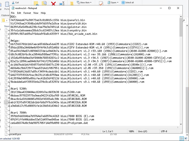
Next you're going to have to locate the proper BIOS files for each system. I can't post them here but they are easy enough to find online with a little searching. Back out of the roms folder and open up the bios folder. In the folder there will be a text file called readme.txt. Open it up to see what BIOS files go where in the bios folder. Most should be placed directly into the bios folder, some will be placed into the same directory as the ROMs, the readme.txt file will tell where to place them and what files you need. TIP: Not every emulator is finicky about BIOS files and will run fine with good files even if they don't have the same MD5 hash. Test each system to see which ones are having a problem. For the problem systems, carefully review your BIOS files. You'll have to find an online tool or utility to get an MD5 hash, Mac and Linux users should have an MD5 CLI command. Once you locate the correct files place them into the proper folder and retry that system until it works.
Figure 21
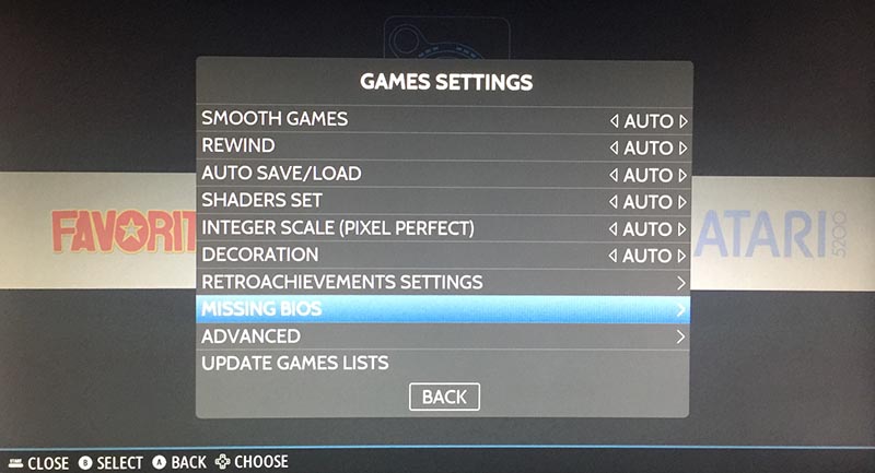
You can actually ask Batocera Linux which BIOS files are missing. Go to the Game Settings option of the main menu as shown below.
Figure 22
Scroll down the Game Settings menu option and locate the Missing Bios menu option as shown below.
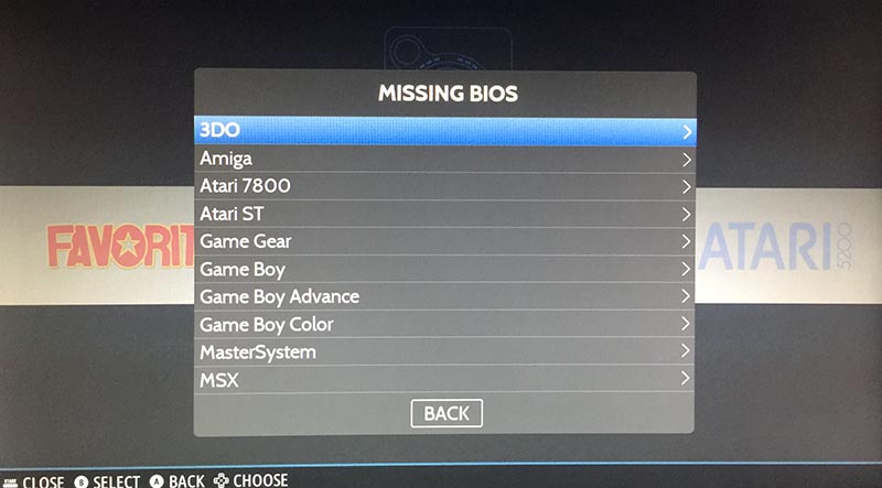
A popup will appear with a break down of the missing BIOS files for each system. You can use it as a reference for the systems that you are having trouble with.
Figure 24
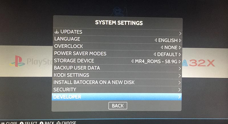
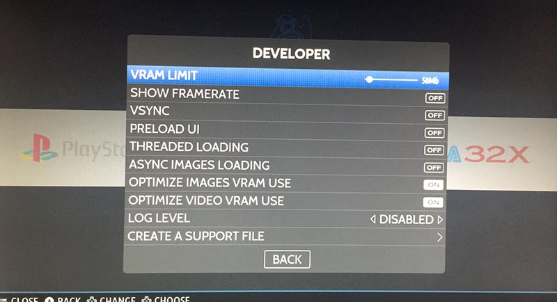
There is just one other thing I want to cover in this section of the tutorial, advanced system settings. If you navigate back to the System Settings menu. Navigate down to the Developer menu and select it and you'll be taken to a menu where you can adjust some lower level settings. I recommend the following settings.
VRAM: 50MB
Show Framerate: OFF
VSYNC: OFF
Preload UI: OFF
Threaded Loading: OFF
Async Image Loading: OFF
Optimize Images VRAM Use: ON
Optimize Video VRAM Use: ON
The images below show the Developer menu and the advanced configuration options.
Figure 25
Figure 26
I've found that without using some of the above settings the system can crash sometimes during fast scrolling. Also I decided to use a smaller amount of RAM so that the emulators have more RAM to use. The UI seems to run fine with 50MB, background music and ROM art work great.
Getting ROM Box Art and Screenshots
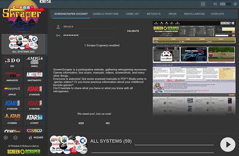
The next step in our project is to setup all the ROM box art and screenshots. Go to https://www.skraper.net/ and download the latest copy of the software. You'll also need to get an account at https://www.screenscraper.fr/. Please donate to both sites, if possible. They are awesome and really help make retro gaming consoles even more amazing by providing access to box art and screenshots for a ton of games.
Once you have your account setup fire up the Skraper UI program and enter in your screenscraper.fr account information. Test the account to make sure that it is working properly. You should have a screen similar to the one depicted below.
Figure 27
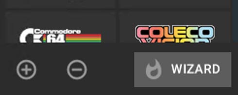
Click on the wizard button on the lower right hand side of the program's UI. You will be prompted to enter in your screenscraper.fr, and select the target ROMs folder you want to process. You should have your micro SD card connected to your computer and you'll want to find and select the roms folder where you pasted in your ROM files. The software will automatically determine each system that has ROMs and run a check against each game to see if there is any artwork available for that game. TIP: Don't run the wizard against all your systems. Things can break and then you won't get the proper results. Run the software one system at a time. Sometimes if you don't get ROM art results wait a few hours and try that system again. This approach worked for me and I was able to get nice results for all of my systems. The wizard button is depicted below.
Figure 28
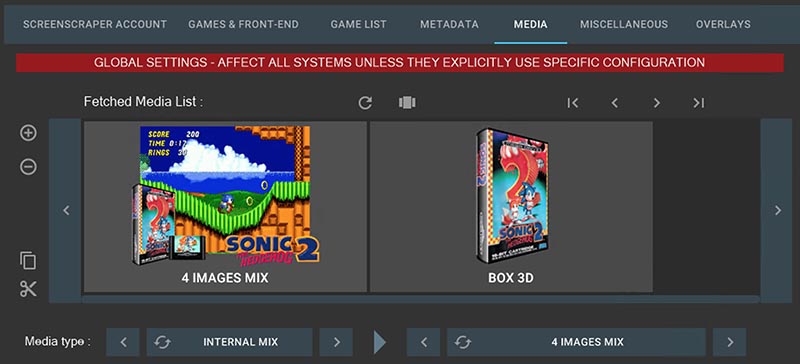
The type of artwork that the software builds is really quite awesome. Take a look below at a sample of the default graphic it will generate for you.
Figure 29
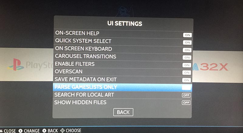
Once you have collected all the ROM box art and screenshots you have to adjust one UI Settings option. Select the UI Settings main menu option and scroll down to the Parse Gamelists Only option and set it to on. This will make it so that the UI only shows the games in the gamelist.xml file. If you use the box art scraping software you will have good XML files and should use this option. You can always adjust the games in the XML files by hand if necessary.
Figure 30
That wraps up our build tutorial for the Monku R4 / ODROID-N2 retro gaming console. A screenshot of what the UI looks like is shown below. I hope you enjoyed it and that it helps you to build an awesome retro gaming system. For advanced emulator configurations look at the next section in the tutorial.
Figure 31
Advanced Emulator Settings
This section is an add on and contains information on how to get specific emulators up and running and ensure they are stable.
Sega CD Problem: Games start to load up and then crash after a few seconds.
Solution: Get the US set of BIOS files and make sure they have the same hash code as required by Batocera Linux. You can check BIOS issues using the menu options listed in the tutorial above to see which files the system expects.
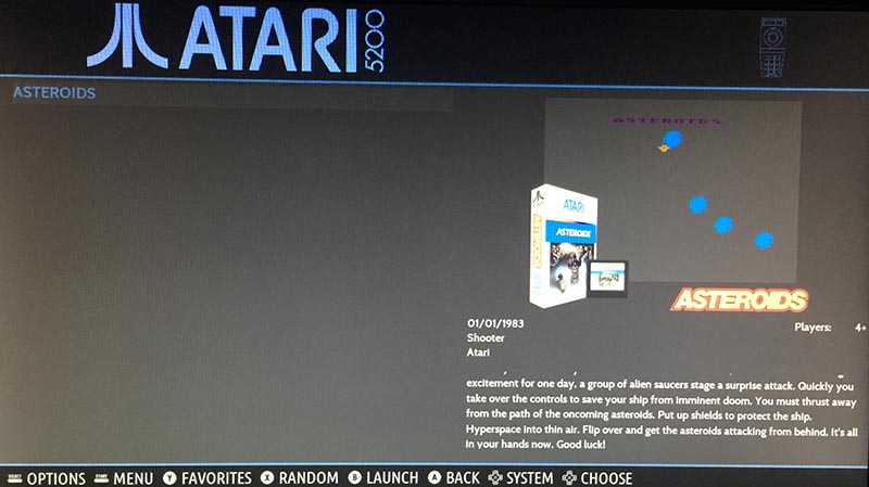
Atari 5200 Problem: Games either crash with no display or they get to an emulator error screen saying there was a loading issue.
Solution: Use a single game to get into the emulator menu where you can then load different ROMs and change the cartridge type. For me the game that worked the best was Asteroids. It will error out but in the emulator menu you can select the directory to look for ROMs, this should be a separate directory than the Batocera Linux one. You should only have your launch title in the Batocera aware directory. You can also change what cartridge type should be used to load in a ROM using the emulator options. Choosing the Atari standard usually fixes any ROM loading issues. It is a bit strange but setting it up this way will ensure that games load and you have control over how they are loaded up.
Commodore 64 Problem: The emulator runs in a small square on the bottom left hand side of the screen.
Solution: Cancel out the game load by hitting the B button. You should be able to get into the emulator options. Under the video/screen settings choose full screen. Then back out to the main menu and go to the settings management option to save your settings. This will ensure that the emulator will start off in full screen mode every time.
Sega Genesis Problem: Your Sega Genesis games are crashing and are not stable.
Solution: Load up the SD card on a Windows machine or a Mac. Go to the folder batocera/system/batocera.conf. Scroll to the bottom of the file until you see megadrive entries. Add in the following lines:
megadrive.core=picodrive
megadrive.emulator-libretro
This will force the system to run the ROMs using a different emulator that isn't selectable from the UI menus. Your games will be more stable and you should have no more issues.
Nintendo 64 Problem: Your Nintendo 64 emulator crashes on exit and Batocera Linux fails to load up again.
Solution: Set the default emulator and core for Nintendo 64 ROMs to emulator libretro and core parallel_n64. This combination has worked great for me. I can exit out of the N64 emulator and get back into Batocera Linux to choose a new system to run.
SSH Login
You can login into your box over the network using the default root login, username: root, password: linux.
2. Flash the image using Etcher to your SD card / eMMC.
3. Insert that card to your Odroid XU4 for the initial boot sequence. It will resize its root file system to fit into your flash memory capacity. Then, do the package upgrade:
$ apt update && apt full-upgrade -y
If it fails with a message mentioning a locking problem, wait for about 5~10 minutes and try again.
4. Mark the linux-kernel-5422 package as “not to be upgraded”:
$ apt-mark hold linux-odroid-5422.
5. Reboot, then power off and connect your SD card / eMMC to your PC.
The G Spot: Your Goto Destination for All Things That are Android Gaming: Google Drops the Ball; Giphy is a Ball; and ODROID-N2 Wins it ALL!
January 1, 2020By Dave ProchnowAndroid, Gaming
Well that was special, wasn’t it? If you’re one of the thousands of Google Stadia Founder’s Edition subscribers, then you know exactly how Google dropped the ball on launch day. This official Google Stadia Tweet pretty much sums up the entire mess:
“Here’s the latest update: If you ordered and paid for Founder’s Edition, you should now have your Stadia access code. Pre-orders and access codes for Premiere Edition will start shipping early next week. Thanks for sticking with us!”
Figure 1 - A game logo with a bright future. Image courtesy of Google Stadia.
On the surface, that sounds innocuous enough, but this Tweet was issued three days after launch day. As you probably have now learned, or might have guessed from reading this article’s title, a huge swath of early Stadia adopters were left holding the streaming game service bag with no games to stream. Sure everything eventually worked out, but this wasn’t the only hiccup to mar Google’s attempt at “providing AAA gaming on any device, any time, anywhere.”
In another Tweet (later deleted) from the official Google Stadia there was a claim that the upcoming AAA thriller, Red Dead Redemption 2, would run at 4K quality. Likewise, Google Stadia head honcho, Phil Harrison has stated in previous comments to this column, that ALL games would be running in 4K quality at 60 fps. The only catch here is that at least two game developers (Destiny 2 and Red Dead Redemption 2) have clearly and explicitly stated that their titles do NOT run at those specifications. In fact, these two titles are actually upscaled to mimic 4K at 60fps.
While this isn’t a smoking gun for conspiracy mongers to embrace, it does clearly indicate how this type of technology is in its infancy and, as such, there will be some growing pangs and hiccups along the path to a viable streaming gaming service that truly works on any device, any time, and anywhere.
Giphy Gaming
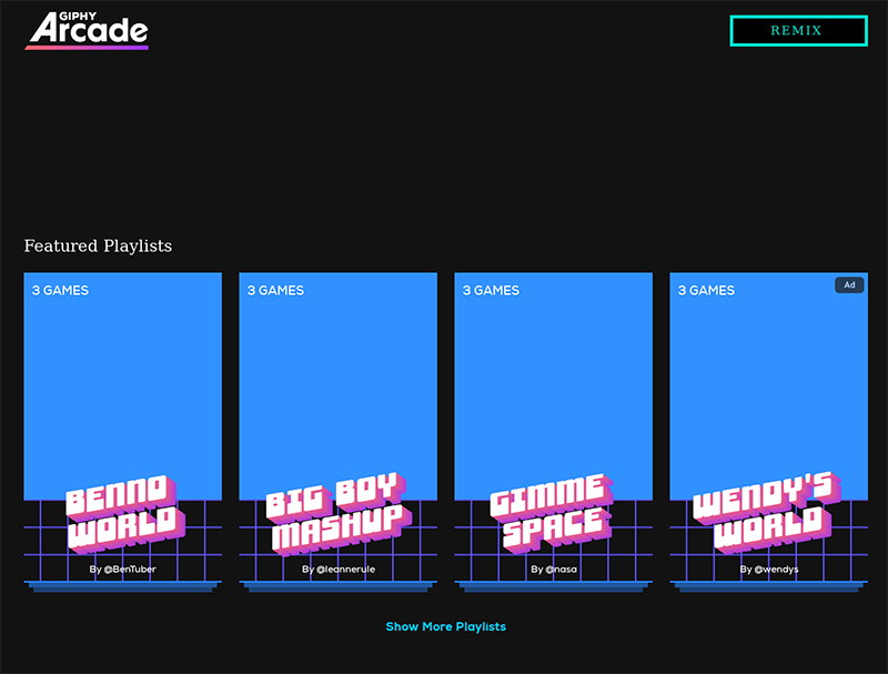
If you’re looking for an alternative to streamed 4K, 60 fps gaming, then how about some retro-like arcade-like gaming? Sponsored by the online GIF search engine website, Giphy, a new game service features short, micro-sized versions of some arcade classics. For example, a Giphy version of Asteroids (called “Blast 20 Asteroids” inside the “Gimme Space” Featured Playlist) accompanied by music and sound effects can be played inside most browsers on any web-connected device.
Figure 2 - GIF arcade gaming.
Called Giphy Arcade, the game-play on this new service is ridiculously short and the graphics are heavily influenced by GIFs and emojis. For example, returning to the previously mentioned “Blast 20 Asteroids” game, the movable laser-firing cannon found in Asteroids is replaced by a spacewalking astronaut GIF with a laser-firing fist.
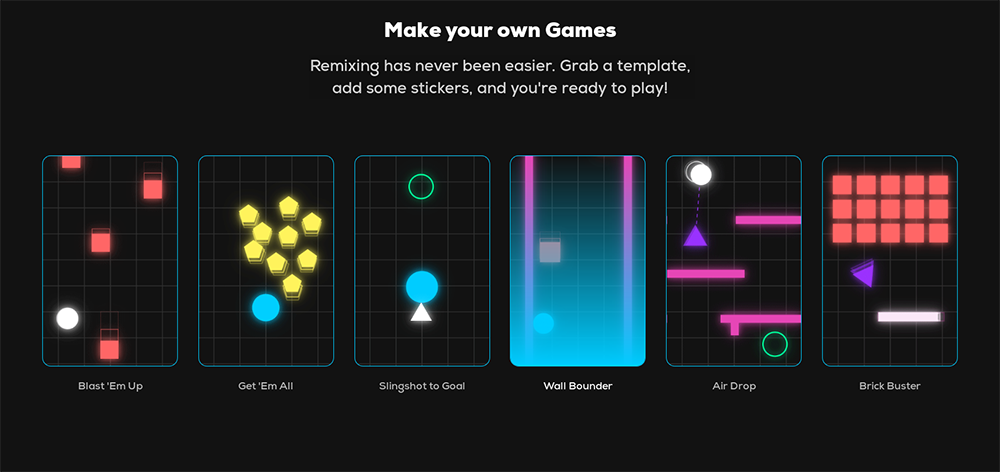
Figure 3 - Roll your own arcade game with the help of some templates.
Figure 4 - When you’ve finished your game masterpiece, share it with the world.
Once you get tired of playing these playlist-featured games, you can try your hand at making your own game. More like a mashup of GIFs, music, emojis, and templates, these handmade masterpieces can be played and shared with other Giphy visitors. Currently, the options for game making are a little rough around the edges, but you can get in on the ground floor of retro-like, arcade-like gaming right now and become a “rockstar” in Giphy Arcade gaming.
An ODROID Gaming Honor
Anyone who follows retro-gaming, gaming emulators, and handheld gaming devices knows the name ETA Prime. Operating as a major gaming presence on YouTube and with over 350K subscribers, ETA Prime is also one of the most prolific video publishers on YouTube with multiple uploads every week.
Figure 5 - ETA Prime is a video powerhouse for SBC commentary.
Suffice it to say, that when ETA Prime publishes a video, a LOT of people pay attention. This was the case in mid-November when a video titled, “What’s the Best Single Board Computer for Android” appeared on his channel.
Although the video’s title mentioned “… for Android,” this is ETA Prime-speak for generalized “Android Gaming” or more specifically, Android multimedia consumption—a one-stop video, movie, and gaming marketplace operating under the guise of Android.
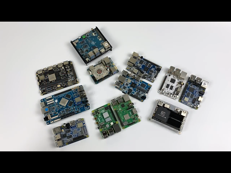
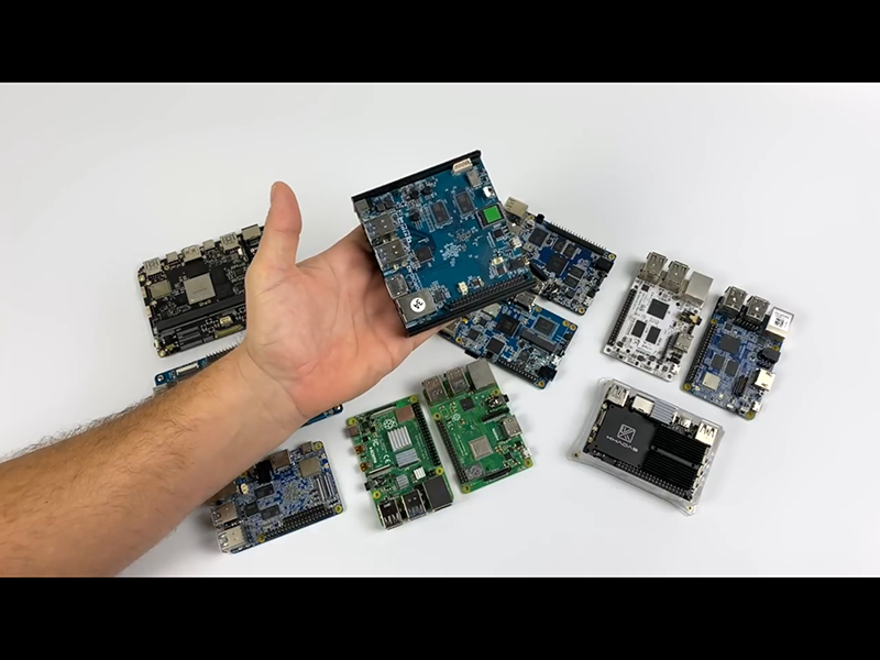
During the course of this video, ETA Prime compares 12 different single board computers (SBCs). Each of these models are powerful contemporary SBCs that are popular with today’s hobbyists, system designers, and industrial-grade researchers. Watching the 7 minute 33 second video is a great high-level summary of the current state of SBCs. There are a total of 12 SBCs that ETA Prime highlights and each one is topnotch in its specifications and performance.
Figure 6 - The 12 featured SBCs; can you ID them all?
The excitement mounts as the video nears its midway point, where at about the 3 minute 38 second mark, the “2019, best board for running Android” is announced. And that SBC is the ODROID-N2. In his typical and methodical fashion, ETA Prime then devotes the remainder of the video to supporting his claim with benchmarks, third-party OS releases, and game testing.
Figure 7 - And the winner is … ODROID-N2.
(Figure 7 - And the winner is … ODROID-N2.)
Therefore, if you’re looking for an Android SBC look no further than the ODROID-N2.
Kubernetes On An ODROID-N2 Cluster
January 1, 2020By Swaminathan BhaskarDevelopment, ODROID-N2, Tutorial
Overview
Kubernetes (or k8s for short) is an extensible open source container orchestration platform designed for managing containerized workloads and services at scale. It helps in automated deployment, scaling, and management of container centric application workloads across a cluster of nodes (bare-metal, virtual, or cloud) by orchestrating compute, network, and storage infrastructure on behalf of those user workloads.
The two main types of nodes in a Kubernetes cluster are:
Master: this node acts as the Control Plane for the cluster. It is responsible for all application workload deployment, scheduling, and placement decisions as well as detecting and managing changes to the state of deployed applications. It is comprised of a Key-Value Store, an API Server, a Scheduler, and a Controller Manager.
Worker Node(s): node(s) that actually run the application containers. They are also on occasions referred to as Minion(s). The Master is also a node, but is not targeted for application deployment. It is comprised of an agent called kubelet, a network proxy called kube-proxy, and a Container Engine.
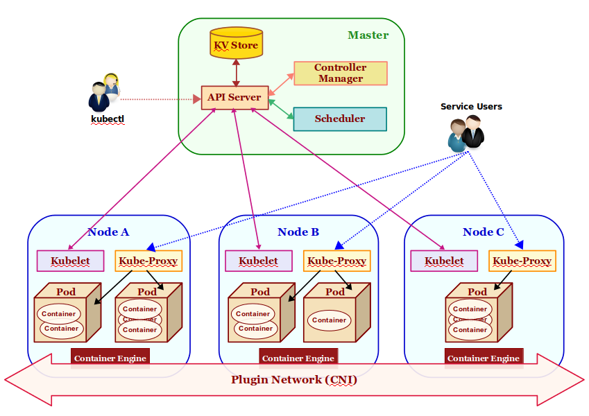
The following Figure-1 illustrates the high-level architectural overview of Kubernetes:
Figure 1
The core components that make a Kubernetes cluster are described as follows:
KV Store: a highly reliable, distributed, and consistent key-value data store used for persisting and maintaining state information about the various components of the Kubernetes cluster. By default, Kubernetes uses etcd as the key-value store.
API Server: acts as the entry point for the Control Plane by exposing an API endpoint for all interactions with and within the Kubernetes cluster. It is through the API Server that requests are made for deployment, administration, management, and operation of container based applications. It uses the key-value store to persist and maintain state information about all the components of the Kubernetes cluster.
Pod(s): it is the smallest unit of deployment in Kubernetes . One or more containers run inside it. Think of it as a logical host with shared network and storage. Application pods are scheduled to run on different worker nodes of the Kubernetes cluster based on the resource needs and application constraints. Every pod within the cluster gets its own unique ip-address. The application containers within a pod communicate with each other using localhost. Pod(s) are also the smallest unit of scaling in Kubernetes. In addition, Pod(s) are ephemeral - they can come and go at any time.
Scheduler: responsible for scheduling application pod(s) to run on the selected worker node(s) of the Kubernetes cluster based on the application resource requirements as well as application specific affinity constraints.
Service: provides a stable, logical networking endpoint for a group of pod(s) (based on a label related to an application pod) running on the wor2ker node(s) of the Kubernetes cluster. They enable access to an application via service-discovery and spread the requests through simple load-balancing. To access an application, each service is assigned a cluster-wide internal ip-address:port.
Controller Manager: manages different types of controllers that are responsible for monitoring and detecting changes to the state of the Kubernetes cluster (via the API server) and ensuring that the cluster is moved to the desired state. The different types of controllers are:
Node Controller => responsible for monitoring and detecting the state & health (up or down) of the worker node(s) in the Kubernetes cluster.
ReplicaSet => previously referred to as the Replication Controller and is responsible for maintaining the desired number of pod replicas in the cluster.
Endpoints Controller => responsible for detecting and managing changes to the application service access endpoints (list of ip-address:port).
Plugin Network: acts as the bridge (overlay network) that enables communication between the pod(s) running on different worker node(s) of the cluster. There are different implementations of this component by various 3rd-parties such as calico, flannel, weave-net, etc. They all need to adhere to a common specification called the Container Network Interface or CNI for short.
kubelet: an agent that runs on every worker node of the Kubernetes cluster. It is responsible for creating and starting an application pod on the worker node and making sure all the application containers are up and running within the pod. In addition, it is also responsible for reporting the state and health of the worker node, as well as all the running pods to the master via the API server.
kube-proxy: a network proxy that runs on each of the worker node (s) of the Kubernetes cluster and acts as an entry point for access to the various application service endpoints. It routes requests to the appropriate pod (s) in the cluster.
Container Engine: a container runtime that runs on each of the worker node(s) to manage the lifecycle of containers such as getting the images, starting and stopping containers, etc. The commonly used container engine is Docker.
kubectl: command line tool used for interfacing with the API Server. Used by administrators (or operators) for deployment and scaling of applications, as well as for the management of the Kubernetes cluster.
Installation and System Setup
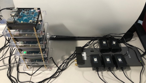
The installation will be on a 5-node ODROID-N2 Cluster running Armbian Ubuntu Linux.
The following Figure-2 illustrates the 5-node ODROID-N2 cluster in operation:
Figure 2
For this tutorial, let us assume the 5-nodes in the cluster to have the following host names and ip addresses:
Host name IP Address
Open a Terminal window and open a tab for each of the 5 nodes my-n2-1 thru my-n2-5. In each of the Terminal tabs, ssh into the corresponding node.
Each of the nodes my-n2-1 thru my-n2-5 need to have a unique identifier for the cluster to operate without any collisions. The unique node identifier is located in the file /etc/machine-id and we see all the nodes my-n2-1 thru my-n2-5 having the same value. This needs to be * FIXED*. On each of the nodes my-n2-1 thru my-n2-5, execute the following commands:
For version 1.16 of Kubernetes (the version at the time of this article), the recommended Docker version is 18.09.
ATTENTION: For Docker CE 19.xx (and above)
Ensure the version of Docker installed is *18.09*. Else will encounter the following error:
[ERROR SystemVerification]: unsupported docker version: 19.xx
We need to check for the latest package of Docker 18.09 in the repository. On any of the nodes (we will pick my-n2-1), execute the following command:
Output.2
Reading package lists... Done
Building dependency tree
Reading state information... Done
The following additional packages will be installed:
aufs-tools cgroupfs-mount containerd.io docker-ce-cli git git-man liberror-perl pigz
Suggested packages:
git-daemon-run | git-daemon-sysvinit git-doc git-el git-email git-gui gitk gitweb git-cvs git-mediawiki git-svn
The following NEW packages will be installed:
aufs-tools cgroupfs-mount containerd.io docker-ce docker-ce-cli git git-man liberror-perl pigz
0 upgraded, 9 newly installed, 0 to remove and 0 not upgraded.
Need to get 61.3 MB of archives.
After this operation, 325 MB of additional disk space will be used.
Get:1 https://download.docker.com/linux/ubuntu xenial/stable arm64 containerd.io arm64 1.2.10-3 [14.5 MB]
Get:2 http://ports.ubuntu.com/ubuntu-ports bionic/universe arm64 pigz arm64 2.4-1 [47.8 kB]
Get:3 http://ports.ubuntu.com/ubuntu-ports bionic/universe arm64 aufs-tools arm64 1:4.9+20170918-1ubuntu1 [101 kB]
Get:4 http://ports.ubuntu.com/ubuntu-ports bionic/universe arm64 cgroupfs-mount all 1.4 [6320 B]
Get:5 http://ports.ubuntu.com/ubuntu-ports bionic/main arm64 liberror-perl all 0.17025-1 [22.8 kB]
Get:6 http://ports.ubuntu.com/ubuntu-ports bionic-updates/main arm64 git-man all 1:2.17.1-1ubuntu0.4 [803 kB]
Get:7 http://ports.ubuntu.com/ubuntu-ports bionic-updates/main arm64 git arm64 1:2.17.1-1ubuntu0.4 [2941 kB]
Get:8 https://download.docker.com/linux/ubuntu xenial/stable arm64 docker-ce-cli arm64 5:19.03.5~3-0~ubuntu-xenial [29.6 MB]
Get:9 https://download.docker.com/linux/ubuntu xenial/stable arm64 docker-ce arm64 5:18.09.9~3-0~ubuntu-xenial [13.3 MB]
Fetched 61.3 MB in 5s (11.6 MB/s)
Selecting previously unselected package pigz.
(Reading database ... 156190 files and directories currently installed.)
Preparing to unpack .../0-pigz_2.4-1_arm64.deb ...
Unpacking pigz (2.4-1) ...
Selecting previously unselected package aufs-tools.
Preparing to unpack .../1-aufs-tools_1%3a4.9+20170918-1ubuntu1_arm64.deb ...
Unpacking aufs-tools (1:4.9+20170918-1ubuntu1) ...
Selecting previously unselected package cgroupfs-mount.
Preparing to unpack .../2-cgroupfs-mount_1.4_all.deb ...
Unpacking cgroupfs-mount (1.4) ...
Selecting previously unselected package containerd.io.
Preparing to unpack .../3-containerd.io_1.2.10-3_arm64.deb ...
Unpacking containerd.io (1.2.10-3) ...
Selecting previously unselected package docker-ce-cli.
Preparing to unpack .../4-docker-ce-cli_5%3a19.03.5~3-0~ubuntu-xenial_arm64.deb ...
Unpacking docker-ce-cli (5:19.03.5~3-0~ubuntu-xenial) ...
Selecting previously unselected package docker-ce.
Preparing to unpack .../5-docker-ce_5%3a18.09.9~3-0~ubuntu-xenial_arm64.deb ...
Unpacking docker-ce (5:18.09.9~3-0~ubuntu-xenial) ...
Selecting previously unselected package liberror-perl.
Preparing to unpack .../6-liberror-perl_0.17025-1_all.deb ...
Unpacking liberror-perl (0.17025-1) ...
Selecting previously unselected package git-man.
Preparing to unpack .../7-git-man_1%3a2.17.1-1ubuntu0.4_all.deb ...
Unpacking git-man (1:2.17.1-1ubuntu0.4) ...
Selecting previously unselected package git.
Preparing to unpack .../8-git_1%3a2.17.1-1ubuntu0.4_arm64.deb ...
Unpacking git (1:2.17.1-1ubuntu0.4) ...
Setting up aufs-tools (1:4.9+20170918-1ubuntu1) ...
Setting up git-man (1:2.17.1-1ubuntu0.4) ...
Setting up containerd.io (1.2.10-3) ...
Created symlink /etc/systemd/system/multi-user.target.wants/containerd.service → /lib/systemd/system/containerd.service.
Setting up liberror-perl (0.17025-1) ...
Setting up cgroupfs-mount (1.4) ...
Setting up docker-ce-cli (5:19.03.5~3-0~ubuntu-xenial) ...
Setting up pigz (2.4-1) ...
Setting up git (1:2.17.1-1ubuntu0.4) ...
Setting up docker-ce (5:18.09.9~3-0~ubuntu-xenial) ...
update-alternatives: using /usr/bin/dockerd-ce to provide /usr/bin/dockerd (dockerd) in auto mode
Created symlink /etc/systemd/system/multi-user.target.wants/docker.service → /lib/systemd/system/docker.service.
Created symlink /etc/systemd/system/sockets.target.wants/docker.socket → /lib/systemd/system/docker.socket.
Processing triggers for systemd (237-3ubuntu10.33) ...
Processing triggers for man-db (2.8.3-2ubuntu0.1) ...
Processing triggers for libc-bin (2.27-3ubuntu1) ...
Next, we need to ensure we are able to execute the Docker commands as the logged in user without the need for sudo. On each of the nodes my-n2-1 thru my-n2-5, execute the following commands:
$ sudo usermod -aG docker $USER
$ sudo reboot now
Once again, in each of the Terminal tabs, ssh into the corresponding node.
To verify the Docker installation, on each of the nodes my-n2-1 thru my-n2-5, execute the following command:
Next, we need to ensure the packages for Docker and Kubernetes are not updated in the future by the software update process. On each of the nodes my-n2-1 thru my-n2-5, execute the following command:
$ sudo apt-mark hold kubelet kubeadm kubectl docker-ce
The following would be a typical output:
Output.6
kubelet set on hold.
kubeadm set on hold.
kubectl set on hold.
docker-ce set on hold.
By default, Docker uses cgroupfs as the cgroup driver. Kubernetes prefers systemd as the cgroup driver. We need to modify the Docker daemon configuration by specifying options in a JSON file called /etc/docker/daemon.json. On each of the nodes my-n2-1 thru my-n2-5, create the configuration file /etc/docker/daemon.json with the following contents:
Next, we need to restart the Docker daemon for the configuration to take effect. On each of the nodes my-n2-1 thru my-n2-5, execute the following commands:
Note:
Not using the systemd cgroup driver will cause the following error:
[preflight] Running pre-flight checks
[WARNING IsDockerSystemdCheck]: detected "cgroupfs" as the Docker cgroup driver. The recommended driver is "systemd". Please follow the guide at https://kubernetes.io/docs/setup/cri/
To verify the Docker daemon started ok, on each of the nodes my-n2-1 thru my-n2-5, execute the following command:
$ journalctl -u docker
The following would be a typical output:
Output.7
-- Logs begin at Sat 2019-12-14 21:14:19 EST, end at Sat 2019-12-14 21:49:26 EST. --
Dec 14 21:14:26 my-n2-1 systemd[1]: Starting Docker Application Container Engine...
Dec 14 21:14:27 my-n2-1 dockerd[3347]: time="2019-12-14T21:14:27.806496732-05:00" level=info msg="systemd-resolved is running, so using resolvconf: /run/systemd/res
Dec 14 21:14:27 my-n2-1 dockerd[3347]: time="2019-12-14T21:14:27.821800611-05:00" level=info msg="parsed scheme: "unix"" module=grpc
Dec 14 21:14:27 my-n2-1 dockerd[3347]: time="2019-12-14T21:14:27.822661404-05:00" level=info msg="scheme "unix" not registered, fallback to default scheme" module
Dec 14 21:14:27 my-n2-1 dockerd[3347]: time="2019-12-14T21:14:27.824226106-05:00" level=info msg="parsed scheme: "unix"" module=grpc
Dec 14 21:14:27 my-n2-1 dockerd[3347]: time="2019-12-14T21:14:27.824838344-05:00" level=info msg="scheme "unix" not registered, fallback to default scheme" module
Dec 14 21:14:27 my-n2-1 dockerd[3347]: time="2019-12-14T21:14:27.828116839-05:00" level=info msg="ccResolverWrapper: sending new addresses to cc: [{unix:///run/cont
Dec 14 21:14:27 my-n2-1 dockerd[3347]: time="2019-12-14T21:14:27.828945714-05:00" level=info msg="ClientConn switching balancer to "pick_first"" module=grpc
Dec 14 21:14:27 my-n2-1 dockerd[3347]: time="2019-12-14T21:14:27.828101672-05:00" level=info msg="ccResolverWrapper: sending new addresses to cc: [{unix:///run/cont
Dec 14 21:14:27 my-n2-1 dockerd[3347]: time="2019-12-14T21:14:27.830093104-05:00" level=info msg="ClientConn switching balancer to "pick_first"" module=grpc
Dec 14 21:14:27 my-n2-1 dockerd[3347]: time="2019-12-14T21:14:27.832076285-05:00" level=info msg="pickfirstBalancer: HandleSubConnStateChange: 0x400014e610, CONNECT
Dec 14 21:14:27 my-n2-1 dockerd[3347]: time="2019-12-14T21:14:27.844251802-05:00" level=info msg="pickfirstBalancer: HandleSubConnStateChange: 0x40001343a0, CONNECT
Dec 14 21:14:27 my-n2-1 dockerd[3347]: time="2019-12-14T21:14:27.846949059-05:00" level=info msg="pickfirstBalancer: HandleSubConnStateChange: 0x40001343a0, READY"
Dec 14 21:14:27 my-n2-1 dockerd[3347]: time="2019-12-14T21:14:27.851896887-05:00" level=info msg="pickfirstBalancer: HandleSubConnStateChange: 0x400014e610, READY"
Dec 14 21:14:27 my-n2-1 dockerd[3347]: time="2019-12-14T21:14:27.857097768-05:00" level=info msg="[graphdriver] using prior storage driver: overlay2"
Dec 14 21:14:27 my-n2-1 dockerd[3347]: time="2019-12-14T21:14:27.886090322-05:00" level=info msg="Graph migration to content-addressability took 0.00 seconds"
Dec 14 21:14:27 my-n2-1 dockerd[3347]: time="2019-12-14T21:14:27.893602818-05:00" level=info msg="Loading containers: start."
Dec 14 21:14:28 my-n2-1 dockerd[3347]: time="2019-12-14T21:14:28.821256841-05:00" level=info msg="Default bridge (docker0) is assigned with an IP address 172.17.0.0
Dec 14 21:14:29 my-n2-1 dockerd[3347]: time="2019-12-14T21:14:29.134364234-05:00" level=info msg="Loading containers: done."
Dec 14 21:14:29 my-n2-1 dockerd[3347]: time="2019-12-14T21:14:29.374311397-05:00" level=info msg="Docker daemon" commit=039a7df graphdriver(s)=overlay2 version=18.0
Dec 14 21:14:29 my-n2-1 dockerd[3347]: time="2019-12-14T21:14:29.376444960-05:00" level=info msg="Daemon has completed initialization"
Dec 14 21:14:29 my-n2-1 systemd[1]: Started Docker Application Container Engine.
Dec 14 21:14:29 my-n2-1 dockerd[3347]: time="2019-12-14T21:14:29.444607195-05:00" level=info msg="API listen on /var/run/docker.sock"
Dec 14 21:49:11 my-n2-1 dockerd[3347]: time="2019-12-14T21:49:11.323542665-05:00" level=info msg="Processing signal 'terminated'"
Dec 14 21:49:11 my-n2-1 dockerd[3347]: time="2019-12-14T21:49:11.328379659-05:00" level=info msg="stopping event stream following graceful shutdown" error="" m
Dec 14 21:49:11 my-n2-1 systemd[1]: Stopping Docker Application Container Engine...
Dec 14 21:49:11 my-n2-1 systemd[1]: Stopped Docker Application Container Engine.
Dec 14 21:49:11 my-n2-1 systemd[1]: Starting Docker Application Container Engine...
Dec 14 21:49:11 my-n2-1 dockerd[9629]: time="2019-12-14T21:49:11.499488062-05:00" level=info msg="systemd-resolved is running, so using resolvconf: /run/systemd/res
Dec 14 21:49:11 my-n2-1 dockerd[9629]: time="2019-12-14T21:49:11.502141612-05:00" level=info msg="parsed scheme: "unix"" module=grpc
Dec 14 21:49:11 my-n2-1 dockerd[9629]: time="2019-12-14T21:49:11.502209240-05:00" level=info msg="scheme "unix" not registered, fallback to default scheme" module
Dec 14 21:49:11 my-n2-1 dockerd[9629]: time="2019-12-14T21:49:11.502278577-05:00" level=info msg="parsed scheme: "unix"" module=grpc
Dec 14 21:49:11 my-n2-1 dockerd[9629]: time="2019-12-14T21:49:11.502295786-05:00" level=info msg="scheme "unix" not registered, fallback to default scheme" module
Dec 14 21:49:11 my-n2-1 dockerd[9629]: time="2019-12-14T21:49:11.505887217-05:00" level=info msg="ccResolverWrapper: sending new addresses to cc: [{unix:///run/cont
Dec 14 21:49:11 my-n2-1 dockerd[9629]: time="2019-12-14T21:49:11.506035600-05:00" level=info msg="ClientConn switching balancer to "pick_first"" module=grpc
Dec 14 21:49:11 my-n2-1 dockerd[9629]: time="2019-12-14T21:49:11.506181190-05:00" level=info msg="ccResolverWrapper: sending new addresses to cc: [{unix:///run/cont
Dec 14 21:49:11 my-n2-1 dockerd[9629]: time="2019-12-14T21:49:11.506446245-05:00" level=info msg="ClientConn switching balancer to "pick_first"" module=grpc
Dec 14 21:49:11 my-n2-1 dockerd[9629]: time="2019-12-14T21:49:11.506671465-05:00" level=info msg="pickfirstBalancer: HandleSubConnStateChange: 0x40007a2230, CONNECT
Dec 14 21:49:11 my-n2-1 dockerd[9629]: time="2019-12-14T21:49:11.506255319-05:00" level=info msg="pickfirstBalancer: HandleSubConnStateChange: 0x40008b0710, CONNECT
Dec 14 21:49:11 my-n2-1 dockerd[9629]: time="2019-12-14T21:49:11.509814706-05:00" level=info msg="pickfirstBalancer: HandleSubConnStateChange: 0x40008b0710, READY"
Dec 14 21:49:11 my-n2-1 dockerd[9629]: time="2019-12-14T21:49:11.511738887-05:00" level=info msg="pickfirstBalancer: HandleSubConnStateChange: 0x40007a2230, READY"
Dec 14 21:49:11 my-n2-1 dockerd[9629]: time="2019-12-14T21:49:11.525913142-05:00" level=info msg="Graph migration to content-addressability took 0.00 seconds"
Dec 14 21:49:11 my-n2-1 dockerd[9629]: time="2019-12-14T21:49:11.529808838-05:00" level=info msg="Loading containers: start."
Dec 14 21:49:12 my-n2-1 dockerd[9629]: time="2019-12-14T21:49:12.258591473-05:00" level=info msg="Default bridge (docker0) is assigned with an IP address 172.17.0.0
Dec 14 21:49:12 my-n2-1 dockerd[9629]: time="2019-12-14T21:49:12.540886055-05:00" level=info msg="Loading containers: done."
Dec 14 21:49:12 my-n2-1 dockerd[9629]: time="2019-12-14T21:49:12.614462758-05:00" level=info msg="Docker daemon" commit=039a7df graphdriver(s)=overlay2 version=18.0
Dec 14 21:49:12 my-n2-1 dockerd[9629]: time="2019-12-14T21:49:12.614718313-05:00" level=info msg="Daemon has completed initialization"
Dec 14 21:49:12 my-n2-1 dockerd[9629]: time="2019-12-14T21:49:12.640530153-05:00" level=info msg="API listen on /var/run/docker.sock"
Dec 14 21:49:12 my-n2-1 systemd[1]: Started Docker Application Container Engine.
Next, we need to disable disk based swap. For that we need to perform two actions.
First action, on each of the nodes my-n2-1 thru my-n2-5, edit the file /etc/default/armbian-zram-config and change the line ENABLED=true to ENABLED=false.
Second action, on each of the nodes my-n2-1 thru my-n2-5, execute the following commands:
$ sudo systemctl disable armbian-zram-config
$ sudo reboot now
Once again, in each of the Terminal tabs, ssh into the corresponding node.
This completes the installation and system setup of the cluster nodes. Next stop - Kubernetes setup.
Kubernetes Setup
To get started, we will designate the node my-n2-1 as the master node and setup the control plane. To do that, execute the following command on my-n2-1:
$ sudo kubeadm init
The following would be a typical output:
Output.8
[init] Using Kubernetes version: v1.16.3
[preflight] Running pre-flight checks
[preflight] Pulling images required for setting up a Kubernetes cluster
[preflight] This might take a minute or two, depending on the speed of your internet connection
[preflight] You can also perform this action in beforehand using 'kubeadm config images pull'
[kubelet-start] Writing kubelet environment file with flags to file "/var/lib/kubelet/kubeadm-flags.env"
[kubelet-start] Writing kubelet configuration to file "/var/lib/kubelet/config.yaml"
[kubelet-start] Starting the kubelet
[certs] Using certificateDir folder "/etc/kubernetes/pki"
[certs] Generating "ca" certificate and key
[certs] Generating "apiserver" certificate and key
[certs] apiserver serving cert is signed for DNS names [my-n2-1 kubernetes kubernetes.default kubernetes.default.svc kubernetes.default.svc.cluster.local] and IPs [10.96.0.1 192.168.1.51]
[certs] Generating "apiserver-kubelet-client" certificate and key
[certs] Generating "front-proxy-ca" certificate and key
[certs] Generating "front-proxy-client" certificate and key
[certs] Generating "etcd/ca" certificate and key
[certs] Generating "etcd/server" certificate and key
[certs] etcd/server serving cert is signed for DNS names [my-n2-1 localhost] and IPs [192.168.1.51 127.0.0.1 ::1]
[certs] Generating "etcd/peer" certificate and key
[certs] etcd/peer serving cert is signed for DNS names [my-n2-1 localhost] and IPs [192.168.1.51 127.0.0.1 ::1]
[certs] Generating "etcd/healthcheck-client" certificate and key
[certs] Generating "apiserver-etcd-client" certificate and key
[certs] Generating "sa" key and public key
[kubeconfig] Using kubeconfig folder "/etc/kubernetes"
[kubeconfig] Writing "admin.conf" kubeconfig file
[kubeconfig] Writing "kubelet.conf" kubeconfig file
[kubeconfig] Writing "controller-manager.conf" kubeconfig file
[kubeconfig] Writing "scheduler.conf" kubeconfig file
[control-plane] Using manifest folder "/etc/kubernetes/manifests"
[control-plane] Creating static Pod manifest for "kube-apiserver"
[control-plane] Creating static Pod manifest for "kube-controller-manager"
W1215 11:58:08.359442 4811 manifests.go:214] the default kube-apiserver authorization-mode is "Node,RBAC"; using "Node,RBAC"
[control-plane] Creating static Pod manifest for "kube-scheduler"
W1215 11:58:08.366477 4811 manifests.go:214] the default kube-apiserver authorization-mode is "Node,RBAC"; using "Node,RBAC"
[etcd] Creating static Pod manifest for local etcd in "/etc/kubernetes/manifests"
[wait-control-plane] Waiting for the kubelet to boot up the control plane as static Pods from directory "/etc/kubernetes/manifests". This can take up to 4m0s
[apiclient] All control plane components are healthy after 25.513764 seconds
[upload-config] Storing the configuration used in ConfigMap "kubeadm-config" in the "kube-system" Namespace
[kubelet] Creating a ConfigMap "kubelet-config-1.17" in namespace kube-system with the configuration for the kubelets in the cluster
[upload-certs] Skipping phase. Please see --upload-certs
[mark-control-plane] Marking the node my-n2-1 as control-plane by adding the label "node-role.kubernetes.io/master=''"
[mark-control-plane] Marking the node my-n2-1 as control-plane by adding the taints [node-role.kubernetes.io/master:NoSchedule]
[bootstrap-token] Using token: zcp5a6.w03lcuhx068wvkqv
[bootstrap-token] Configuring bootstrap tokens, cluster-info ConfigMap, RBAC Roles
[bootstrap-token] configured RBAC rules to allow Node Bootstrap tokens to post CSRs in order for nodes to get long term certificate credentials
[bootstrap-token] configured RBAC rules to allow the csrapprover controller automatically approve CSRs from a Node Bootstrap Token
[bootstrap-token] configured RBAC rules to allow certificate rotation for all node client certificates in the cluster
[bootstrap-token] Creating the "cluster-info" ConfigMap in the "kube-public" namespace
[kubelet-finalize] Updating "/etc/kubernetes/kubelet.conf" to point to a rotatable kubelet client certificate and key
[addons] Applied essential addon: CoreDNS
[addons] Applied essential addon: kube-proxy
Your Kubernetes control-plane has initialized successfully!
To start using your cluster, you need to run the following as a regular user:
You should now deploy a pod network to the cluster.
Run "kubectl apply -f [podnetwork].yaml" with one of the options listed at:
https://kubernetes.io/docs/concepts/cluster-administration/addons/
Then you can join any number of worker nodes by running the following on each as root:
From the Output.10 above, we can see all the core components (api server, controller manager, etcd, and scheduler) are all up and running.
Now, we need to install an overlay Plugin Network for inter-pod communication. For our cluster, we will choose the weave-net implementation. To install the overlay network on the master node (my-n2-1), execute the following command:
Output.11
serviceaccount/weave-net created
clusterrole.rbac.authorization.k8s.io/weave-net created
clusterrolebinding.rbac.authorization.k8s.io/weave-net created
role.rbac.authorization.k8s.io/weave-net created
rolebinding.rbac.authorization.k8s.io/weave-net created
daemonset.apps/weave-net created
To verify the Weave overlay network started ok, execute the following command on the master node (my-n2-1):
$ kubectl get pods -n kube-system -l name=weave-net -o wide
The following would be a typical output:
Output.12
NAME READY STATUS RESTARTS AGE IP NODE NOMINATED NODE READINESS GATES
weave-net-2sjh4 2/2 Running 0 10m 192.168.1.51 my-n2-1
Additionally, to check the logs for the Weave overlay network, execute the following command on the master node (my-n2-1):
Output.13
INFO: 2019/12/08 17:07:12.422554 Command line options: map[conn-limit:200 datapath:datapath db-prefix:/weavedb/weave-net docker-api: expect-npc:true host-root:/host http-addr:127.0.0.1:6784 ipalloc-init:consensus=0 ipalloc-range:10.32.0.0/12 metrics-addr:0.0.0.0:6782 name:9a:59:d0:9a:83:f0 nickname:my-n2-1 no-dns:true port:6783]
INFO: 2019/12/08 17:07:12.422876 weave 2.6.0
INFO: 2019/12/08 17:07:12.780249 Bridge type is bridged_fastdp
INFO: 2019/12/08 17:07:12.780350 Communication between peers is unencrypted.
INFO: 2019/12/08 17:07:12.804023 Our name is 9a:59:d0:9a:83:f0(my-n2-1)
INFO: 2019/12/08 17:07:12.804267 Launch detected - using supplied peer list: []
INFO: 2019/12/08 17:07:12.844222 Unable to fetch ConfigMap kube-system/weave-net to infer unique cluster ID
INFO: 2019/12/08 17:07:12.844324 Checking for pre-existing addresses on weave bridge
INFO: 2019/12/08 17:07:12.853900 [allocator 9a:59:d0:9a:83:f0] No valid persisted data
INFO: 2019/12/08 17:07:12.866497 [allocator 9a:59:d0:9a:83:f0] Initialising via deferred consensus
INFO: 2019/12/08 17:07:12.866684 Sniffing traffic on datapath (via ODP)
INFO: 2019/12/08 17:07:12.872570 Listening for HTTP control messages on 127.0.0.1:6784
INFO: 2019/12/08 17:07:12.873074 Listening for metrics requests on 0.0.0.0:6782
INFO: 2019/12/08 17:07:13.540248 [kube-peers] Added myself to peer list &{[{9a:59:d0:9a:83:f0 my-n2-1}]}
DEBU: 2019/12/08 17:07:13.558983 [kube-peers] Nodes that have disappeared: map[]
INFO: 2019/12/08 17:07:13.661165 Assuming quorum size of 1
10.32.0.1
DEBU: 2019/12/08 17:07:13.911144 registering for updates for node delete events
For this tutorial, we designate that nodes my-n2-2 thru my-n2-5 to be the worker nodes of this Kubernetes cluster. From Output.8 above, we can determine the kubeadm join command to use on each worker node . For each of the nodes my-n2-2 thru my-n2-5 (in their respective Terminal tab), execute the following command:
Output.14
[preflight] Running pre-flight checks
[preflight] Reading configuration from the cluster...
[preflight] FYI: You can look at this config file with 'kubectl -n kube-system get cm kubeadm-config -oyaml'
[kubelet-start] Downloading configuration for the kubelet from the "kubelet-config-1.17" ConfigMap in the kube-system namespace
[kubelet-start] Writing kubelet configuration to file "/var/lib/kubelet/config.yaml"
[kubelet-start] Writing kubelet environment file with flags to file "/var/lib/kubelet/kubeadm-flags.env"
[kubelet-start] Starting the kubelet
[kubelet-start] Waiting for the kubelet to perform the TLS Bootstrap...
This node has joined the cluster:
* Certificate signing request was sent to apiserver and a response was received.
* The Kubelet was informed of the new secure connection details.
Run 'kubectl get nodes' on the control-plane to see this node join the cluster.
To list all the active nodes in this Kubernetes cluster, execute the following command on the master node (my-n2-1) (after waiting for about 30 secs ):
As is evident from Output.16 above, we see an instance for API Server, etcd, Controller Manager, Scheduler, and Plugin Network (weave-net) all up and running.
To display detailed information about any pod (say the Controller Manager) in the Kubernetes cluster, execute the following command on the master node (my-n2-1):
$ kubectl describe pod kube-controller-manager-my-n2-1 -n kube-system
The following would be a typical output (Rob, I first noticed output seventeen missing "none"):
To list all the application pod(s) running in Kubernetes cluster, execute the following command on the master node (my-n2-1):
$ kubectl get pods
The following would be a typical output:
Output.18
No resources found in default namespace.
To list all the service(s) running in Kubernetes cluster, execute the following command on the master node (my-n2-1):
$ kubectl get services
The following would be a typical output:
Output.19
NAME TYPE CLUSTER-IP EXTERNAL-IP PORT(S) AGE
kubernetes ClusterIP 10.96.0.1  443/TCP 64m
We will create a simple Python web application to display the host name as well as the ip-address when invoked via HTTP. The following are the contents of the simple Python web application stored under the /tmp directory on the master node (my-n2-1):
The following are the contents of the Dockerfile to create a Docker image for the the simple Python web application stored under the /tmp directory on the master node (my-n2-1):
Dockerfile
FROM python:3.7.5-alpine3.9
RUN pip install flask
ADD web-echo.py /web-echo.py
CMD ["python", "/web-echo.py"]
To build a Docker image called py-web-echo with the tag v1.0, execute the following commands on the master node ( my-n2-1):
cd /tmp
docker build -t "py-web-echo:v1.0" .
The following would be a typical output:
Output.20
Sending build context to Docker daemon 3.072kB
Step 1/4: FROM python:3.7.5-alpine3.9
3.7.5-alpine3.9: Pulling from library/python
0362ad1dd800: Pull complete
9b941924aae3: Pull complete
fd7b3613915d: Pull complete
078d60b9b97e: Pull complete
7059e1dd9bc4: Pull complete
Digest: sha256:064d9ce3e91a59535c528bc3c38888023791d9fc78ba9e5070f5064833f326ff
Status: Downloaded newer image for python:3.7.5-alpine3.9
---> 578ec6233872
Step 2/4: RUN pip install flask
---> Running in d248e23dd161
Collecting flask
Downloading https://files.pythonhosted.org/packages/9b/93/628509b8d5dc749656a9641f4caf13540e2cdec85276964ff8f43bbb1d3b/Flask-1.1.1-py2.py3-none-any.whl (94kB)
Collecting Jinja2>=2.10.1
Downloading https://files.pythonhosted.org/packages/65/e0/eb35e762802015cab1ccee04e8a277b03f1d8e53da3ec3106882ec42558b/Jinja2-2.10.3-py2.py3-none-any.whl (125kB)
Collecting Werkzeug>=0.15
Downloading https://files.pythonhosted.org/packages/ce/42/3aeda98f96e85fd26180534d36570e4d18108d62ae36f87694b476b83d6f/Werkzeug-0.16.0-py2.py3-none-any.whl (327kB)
Collecting itsdangerous>=0.24
Downloading https://files.pythonhosted.org/packages/76/ae/44b03b253d6fade317f32c24d100b3b35c2239807046a4c953c7b89fa49e/itsdangerous-1.1.0-py2.py3-none-any.whl
Collecting click>=5.1
Downloading https://files.pythonhosted.org/packages/fa/37/45185cb5abbc30d7257104c434fe0b07e5a195a6847506c074527aa599ec/Click-7.0-py2.py3-none-any.whl (81kB)
Collecting MarkupSafe>=0.23
Downloading https://files.pythonhosted.org/packages/b9/2e/64db92e53b86efccfaea71321f597fa2e1b2bd3853d8ce658568f7a13094/MarkupSafe-1.1.1.tar.gz
Building wheels for collected packages: MarkupSafe
Building wheel for MarkupSafe (setup.py): started
Building wheel for MarkupSafe (setup.py): finished with status 'done'
Created wheel for MarkupSafe: filename=MarkupSafe-1.1.1-cp37-none-any.whl size=12629 sha256=8a200864ca113d03b4de2d951ae4a1d0806a3ff84128349770dfe3fb018a6458
Stored in directory: /root/.cache/pip/wheels/f2/aa/04/0edf07a1b8a5f5f1aed7580fffb69ce8972edc16a505916a77
Successfully built MarkupSafe
Installing collected packages: MarkupSafe, Jinja2, Werkzeug, itsdangerous, click, flask
Successfully installed Jinja2-2.10.3 MarkupSafe-1.1.1 Werkzeug-0.16.0 click-7.0 flask-1.1.1 itsdangerous-1.1.0
Removing intermediate container d248e23dd161
---> 4ee40e66a655
Step 3/4: ADD web-echo.py /web-echo.py
---> 31a0341bf9d7
Step 4/4: CMD ["python", "/web-echo.py"]
---> Running in 1ee52ea10ad3
Removing intermediate container 1ee52ea10ad3
---> 7cd037d24ef7
Successfully built 7cd037d24ef7
Successfully tagged py-web-echo:v1.0
To list all the Docker images on the master node (my-n2-1), execute the following command on the master node (my-n2-1):
$ docker images
The following would be a typical output:
Output.21
REPOSITORY TAG IMAGE ID CREATED SIZE
py-web-echo v1.0 7cd037d24ef7 3 minutes ago 119MB
k8s.gcr.io/kube-proxy v1.17.0 ac19e9cffff5 7 days ago 114MB
k8s.gcr.io/kube-apiserver v1.17.0 aca151bf3e90 7 days ago 166MB
k8s.gcr.io/kube-controller-manager v1.17.0 7045158f92f8 7 days ago 156MB
k8s.gcr.io/kube-scheduler v1.17.0 0d5c120f87f3 7 days ago 93.7MB
python 3.7.5-alpine3.9 578ec6233872 4 weeks ago 109MB
weaveworks/weave-npc 2.6.0 1c672c2f5870 5 weeks ago 36.6MB
weaveworks/weave-kube 2.6.0 81393394d17d 5 weeks ago 111MB
k8s.gcr.io/coredns 1.6.5 f96217e2532b 5 weeks ago 39.3MB
k8s.gcr.io/etcd 3.4.3-0 ab707b0a0ea3 7 weeks ago 363MB
k8s.gcr.io/pause 3.1 6cf7c80fe444 24 months ago 525kB
Note that we built the Docker image on the master node (my-n2-1). Since the pod(s) will be deployed on the worker node(s), we need to ensure the requisite docker images are present in the worker node(s).
For each of the worker nodes my-n2-2 thru my-n2-5 (in their respective Terminal tab), execute the following command:
$ docker pull python:3.7.5-alpine3.9
For each of the worker nodes my-n2-2 thru my-n2-5, execute the following command on the master node (my-n2-1):
Not having the Docker images in the worker node(s) will cause the pod(s) to be stuck in the ContainerCreating status
In Kubernetes, a pod is what encapsulates Docker container(s). To deploy our web application Docker image py-web-echo:v1.0 in our Kubernetes cluster, we need a pod manifest file in YAML format .
The following are the contents of the pod manifest file called web-echo-pod.yaml stored under the /tmp directory on the master node (my-n2-1):
The following section explains the elements of the web-echo-pod.yaml manifest file:
apiVersion: specifies the version of the API (v1 in this example)
kind: specifies the type of Kubernetes object to deploy (Pod in this example)
metadata: associates a name ( web-echo-pod in this example) with the type of Kubernetes object. Also, allows one to tag some labels, which are simple key-value pairs, with the Kubernetes
object. In this example, we have one label with the key app that has a value of web-echo
spec: specifies what is in the pod. In this example, we want to deploy the Docker image py-web-echo:v1.0 which is exposed via the network port 8888
imagePullPolicy: indicates to Kubernetes not to pull the container image
To deploy the pod to our Kubernetes cluster, execute the following command on the master node (my-n2-1):
$ kubectl apply -f /tmp/web-echo-pod.yaml
The following would be a typical output:
Output.22
pod/web-echo-pod created
To list all the application pod(s) running in Kubernetes cluster, execute the following command on the master node (my-n2-1):
$ kubectl get pods -o wide
The following would be a typical output:
Output.23
1
From Output.23, we see that our application pod have been deployed on the node my-n2-2 of our Kubernetes cluster.
To display detailed information about the deployed application pod web-echo-pod, execute the following command on the master node (my-n2-1):
$ kubectl describe pods web-echo-pod
The following would be a typical output:
Output.24
Name: web-echo-pod
Namespace: default
Priority: 0
Node: my-n2-2/192.168.1.52
Start Time: Sun, 15 Dec 2019 14:58:21 -0500
Labels: app=web-echo
Annotations: kubectl.kubernetes.io/last-applied-configuration:
{"apiVersion":"v1","kind":"Pod","metadata":{"annotations":{},"labels":{"app":"web-echo"},"name":"web-echo-pod","namespace":"default"},"spe...
Status: Running
IP: 10.44.0.1
IPs:
IP: 10.44.0.1
Containers:
web-echo:
Container ID: docker://0af2c99fd074b5ee3c0b9876eb9ad44ca446400c2190b4af6fa1a18543bff723
Image: py-web-echo:v1.0
Image ID: docker://sha256:7cd037d24ef7c842ffe005cfcb548a802fc13661c08c8bb4635c365f77e5a3aa
Port: 8888/TCP
Host Port: 0/TCP
State: Running
Started: Sun, 15 Dec 2019 14:58:23 -0500
Ready: True
Restart Count: 0
Environment:
Mounts:
/var/run/secrets/kubernetes.io/serviceaccount from default-token-tvl5x (ro)
Conditions:
Type Status
Initialized True
Ready True
ContainersReady True
PodScheduled True
Volumes:
default-token-tvl5x:
Type: Secret (a volume populated by a Secret)
SecretName: default-token-tvl5x
Optional: false
QoS Class: BestEffort
Node-Selectors:
Tolerations: node.kubernetes.io/not-ready:NoExecute for 300s
node.kubernetes.io/unreachable:NoExecute for 300s
Events:
Type Reason Age From Message
---- ------ ---- ---- -------
Normal Scheduled 7m39s default-scheduler Successfully assigned default/web-echo-pod to my-n2-2
Normal Pulled 7m38s kubelet, my-n2-2 Container image "py-web-echo:v1.0" already present on machine
Normal Created 7m38s kubelet, my-n2-2 Created container web-echo
Normal Started 7m37s kubelet, my-n2-2 Started container web-echo
From the Output.23 (as well as Output.24) above, we see the ip-address of the deployed web application to be 10.44.0.1.
To test the deployed web application using the curl command, execute the following command on any of the nodes my-n2-1 through my-n2-5:
$ curl http://10.44.0.1:8888
The following would be a typical output:
Output.25
Hello from container -> web-echo-pod [10.44.0.1]
To display the logs of the deployed web application web-echo-pod, execute the following command on the master node (my-n2-1):
$ kubectl logs web-echo-pod
The following would be a typical output:
Output.26
* Serving Flask app "web-echo" (lazy loading)
* Environment: production
WARNING: This is a development server. Do not use it in a production deployment.
Use a production WSGI server instead.
* Debug mode: off
* Running on http://0.0.0.0:8888/ (Press CTRL+C to quit)
10.32.0.1 - - [15/Dec/2019 20:11:33] "GET / HTTP/1.1" 200 -
10.36.0.0 - - [15/Dec/2019 20:11:58] "GET / HTTP/1.1" 200 -
To delete the deployed web application web-echo-pod, execute the following command on the master node (my-n2-1):
$ kubectl delete pod web-echo-pod
The following would be a typical output:
Output.27
pod "web-echo-pod" deleted
It is *NOT* that common to deploy a single Pod. It is more common to deploy a higher level Kubernetes object called a ReplicaSet . A ReplicaSet defines how many replicas of a Pod need to be deployed and maintained in the Kubernetes cluster.
The following are the contents of the ReplicaSet manifest file called web-echo-rs.yaml stored under the /tmp directory on the master node (my-n2-1):
The following section explains some of the elements of the web-echo-rs.yaml manifest file:
apiVersion: specifies the version of the API (apps/v1 in this example)
replicas: indicates the desired instances of the Pod to be running in the Kubernetes cluster
selector: identifies and selects a group of Kubernetes objects with the same key-value label (key app and value web-echo in this example)
template: is the embedded specification for a Pod
To deploy the ReplicaSet to our Kubernetes cluster, execute the following command on the master node (my-n2-1):
$ kubectl apply -f /tmp/web-echo-rs.yaml
The following would be a typical output:
Output.28
replicaset.apps/web-echo-rs created
To list all the deployed ReplicaSet(s) running in Kubernetes cluster, execute the following command on the master node (my-n2-1 ):
$ kubectl get replicasets -o wide
The following would be a typical output:
Output.29
NAME DESIRED CURRENT READY AGE CONTAINERS IMAGES SELECTOR
web-echo-rs 3 3 3 7m web-echo py-web-echo:v1.0 app=web-echo
To display detailed information about the deployed ReplicaSet named web-echo-rs, execute the following command on the master node ( my-n2-1):
$ kubectl describe replicasets web-echo-rs
The following would be a typical output:
Output.30
Name: web-echo-rs
Namespace: default
Selector: app=web-echo
Labels:
Annotations: kubectl.kubernetes.io/last-applied-configuration:
{"apiVersion":"apps/v1","kind":"ReplicaSet","metadata":{"annotations":{},"name":"web-echo-rs","namespace":"default"},"spec":{"replicas":3,...
Replicas: 3 current / 3 desired
Pods Status: 3 Running / 0 Waiting / 0 Succeeded / 0 Failed
Pod Template:
Labels: app=web-echo
Containers:
web-echo:
Image: py-web-echo:v1.0
Port: 8888/TCP
Host Port: 0/TCP
Environment:
Mounts:
Volumes:
Events:
Type Reason Age From Message
---- ------ ---- ---- -------
Normal SuccessfulCreate 14m replicaset-controller Created pod: web-echo-rs-xn94l
Normal SuccessfulCreate 14m replicaset-controller Created pod: web-echo-rs-9x9b9
Normal SuccessfulCreate 14m replicaset-controller Created pod: web-echo-rs-tbd49
To list all the application pod(s) running in Kubernetes cluster, execute the following command on the master node (my-n2-1):
$ kubectl get pods -o wide
The following would be a typical output:
Output.31
NAME READY STATUS RESTARTS AGE IP NODE NOMINATED NODE READINESS GATES
web-echo-rs-9x9b9 1/1 Running 0 63s 10.42.0.1 my-n2-4
web-echo-rs-tbd49 1/1 Running 0 63s 10.44.0.1 my-n2-2
web-echo-rs-xn94l 1/1 Running 0 63s 10.36.0.1 my-n2-3
From Output.31, we see that our application pod(s) have been deployed on the 3 nodes my-n2-2, my-n2-3, and my-n2-4 with unique ip-addresses of 10.44.0.1, 10.36.0.1, and 10.42.0.1 respectively.
As indicated early on, application pod(s) are ephemeral. They can come up and go at any time. This means their ip-address(es) can change any time. We need a higher level abstraction that provides a stable ip-address for other application pod(s) to use. This is where a Service object comes in handy. It provides a single stable ip-address for other applications to use and distributes the load across the different backend application pod(s) it is fronting.
There are 3 types of Service(s) in Kubernetes:
ClusterIP: exposes the Service on an ip-address that is internal to the Kubernetes cluster. This means the Service is accessible from *ONLY* within the Kubernetes cluster. This is the default type
NodePort: exposes the Service on each worker node's ip-address at a high port in the range 30000 to 32767. Applications external to the Kubernetes cluster are be able to access the Service at the worker node's ip-address and the assigned node port
LoadBalancer: 1exposes the Service externally using a cloud providers Load Balancer such as AWS, Azure, or Google Cloud
The following are the contents of the ClusterIP based Service manifest file called web-echo-svc-cip.yaml stored under the /tmp directory on the master node (my-n2-1):
To delete the deployed web-echo-svc object, execute the following command on the master node (my-n2-1):
$ kubectl delete service web-echo-svc
The following would be a typical output:
Output.36
service "web-echo-svc" deleted
The following are the contents of the NodePort based Service manifest file called web-echo-svc-nop.yaml stored under the /tmp directory on the master node (my-n2-1):
Pearl Linux Motion Video Surveillance System With Kodi: Advanced Visual Monitoring Using An ODROID-C2
January 10, 2020By @pearllinuxODROID-C2, Tutorial
I created a video surveillance image based on Ubuntu 18.04 using the 3.16.75 kernel, featuring pre-installed and active upon first boot Motion Video Surveillance Software running in User Mode not root. It includes a pre-installed Apache Web Server and WebMin to manage your system through web interface, and boots into Pearl's Lightweight MATE desktop with most features from Pearl's 7.0 release.
Features
Odroid C2 Pearl Linux Image with Kernel 3.16.75
Motion Video Surveillance preinstalled and active upon boot
Webmin and Apache Web Server preconfigured and active upon boot
latest MATE desktop envirnoment
First, download the image then use Etcher (https://etcher.io) to write the image to your SD card or eMMC module. Upon first boot, the system will automatically resize and use all of the available space of your device. Give the system 2-3 minutes after the screen goes blank, then remove power to C2 then reapply power.
To use KODI, logout and log back into a Kodi session rather than Mate. No password is required to log in under the lightdm display manager. The username is either “root” or “odroid”, and the password is “odroid”. You may change the password from the command prompt or in control panel.
Video Surveillance
This Pearl release comes with Motion Video Surveillance version 4.2.2-1pearl7.3 We made a Debian .deb package and added a Basic Camera Viewer (one 2 up, and one for 4 up). The image is ready out of the box, with the only exception that your actual IP address for your computer may not be the same as the one set up on our LAN. We are using the 192.168.1.0 network, which is one of the most common (others are may be 10.0.0.1 or 192.168.0.1).
The location of the camera monitor is at /opt/pearl/mcm. There, you will find 2 files for the 2 up monitor and 2 files for the 4 up. The HTML file is where
you will change the IP address if it is not the same. The 2 up and 4 up monitoring are
both set to monitor only one camera that is attached to the ODROID-C2 itself. The others
are being pulled from other computers on your LAN running the motion software. You can download and install our version of Motion from our repositories at
http://apt.pearllinux.com/pool/main/m/motion/motion_4.2.2-1pearl7.3_arm64.deb. Other images are available at http://apt.pearllinux.com/pool/main/m/motion/.
Release notes
Because the video surveillance starts at boot, the directory /var/lib/motion will be
Add pictures and short video clips to that directory automatically. If using a 16GB
Micro SD card, you will want to watch that directory because it can fill up the card quickly. You can change any directives including turning the automatic creation of these files
in the main Motion config file located at /etc/motion/montion.conf.
January 10, 2020By @Luke.goAndroid, Development, Tutorial
Have you ever tried to connect a peripheral device to the GPIO pins on your ODROID SBC with the Android OS? For example, you wished to connect a switch to launch an application or you wanted to connect a dimming sensor. The first problem you will face would be the difficulty to handle the GPIO pins from your Android application or service and maybe you would be faced with permission problems to access a GPIO, PWM or I2C, since a general Android application is denied access to a hardware resource. The alternative solution is to port a low-level library such as wiringPi based on C/C++, but it will be required to interface to your application through JNI (Java Native Interface) using NDK. Still, you have to figure out the permission problem.
Google has introduced yet another Operating System (OS) known as “Android Things”, that is designed to run on light embedded devices and offers the framework with Java to handle peripherals. My idea was to incorporate the Android Things framework into ODROID software and let users use the expansion pins easily. However, the problem is that this OS is not open source, therefore, I had to implement the code in the Android for ODROID. Fortunately, Google opens the framework APIs with its document and Android Things SDK. This fact encouraged me to implement the full stack of the framework that works like Android Things, from bottom to top.
I used some APIs from the Android Things’ Peripheral managing parts. It has many other features, but these are not needed for our task. I made interfaces for using the Android Things API. For processing and managing the request from user-layer via API, I built the server and client architecture and connected it to the hardware layer via wiringPi to control real hardware. Initially, GPIO, I2C and PWM features were implemented, because people use them more often than other features like SPI and UART. Explaining all of the implementation is best, but I will just show you how to use it. This tact will be more useful.
Since I utilized the process of reverse engineering. My solution can become incompatible with the real Android Things OS and/or degrade its performance. However, I expect that users who previously wanted to use GPIO pins on Android will be relieved from some of the difficulty of working in C through my work. Let me show you an example of Android Things about GPIO, I2C and PWM to learn how to use it.
Fig. 01 - Architecture
There is nothing as simple as using the Android Studio to create, compile, and test an application or service that contains Android Things. You just need to install the Android Studio, and add official option and official code to use Android Things, and install a package to ODROID via otg port. and execute a package. It just works! That is all. you do not need to do anything else.
I uploaded all of the example code to my github repository (https://github.com/xiane/thingsGpioExample). And each of the examples is separated by branches. On the master branch, you can control the GPIO pin. On the i2c_16x4 branch, you can use 16x4 lcd through I2C. On the PWM branch, you can control the PWM. and on the i2c_weather_board branch, you can use a weatherboard. Please use and test it for your own projects.
You can get an available GPIO list via the getGpioList method. This method provides an available GPIO name list. So you can select from the list to use. Each pin has a name that comes from a physical pin number. Yes, the GPIO pin name is pin number. You can get GPIO instance through openGpio method with pin name by parameter.
List gpioList = manager.getGpioList();

Gpio gpio = manager.openGpio(gpioList.get(0));
// or Gpio gpio = manager.openGpio(“7”);
In this example, I will introduce to you how to use a GPIO pin as an output. In the example, I want to use pin #7 as output and if I push the button in my application, an LED that is connected to GPIO pin #7 will be lit. Like above, after getting a GPIO instance, you can set the direction IO of the GPIO pin. You can set direction by setDirection method and direction values are DIRECTION_IN, DIRECTION_OUT_INITIALLY_HIGH and DIRECTION_OUT_INITIALLY_LOW. I chose DIRECTION_OUT_INITIALLY_LOW to make the GPIO value low.
Then you can set value via the setValue method. If you want to make output value high or 1, you should pass the True parameter or you can pass the false parameter as low or 0. In this example, I get input from the application's button. So when you click the button an LED lights up.
Android Things also provides other methods like getValue, setActiveType, setEdgeTriggerType and registerGpioCallback. You can learn about it from the official web page. However, the ODROID still does not provide registerGpioCallback properly. In particular, Callback configuration using Handler has not been implemented yet. I hope it will be implemented.