

Things You will Need (Use your nearest ODROID supplier) --
- ODROID-N2 ~ $60 - $70
- ODROID-N2 Case $4
- ODROID-N2 Power Supply $6
- eMMC (If you choose to use 32GB or 64GB): ~ $27 - $40, or
- microSD (If you choose to use 16GB, 32GB or 64GB): ~ $8 - $14
- microSD to USB Adapter: $11
- eMMC to USB Adapter: $10
- WIFI Modules (Module 0, 4 or 5A - If you do not have a wired internet connection): ~ $5 - $8
- Tinkering Kit (Breakout breadboard, LEDs, Jumpers, Buttons, Resistors): $16
- USB Mouse and Keyboard
- HDMI Monitor or TV
- HDMI Cable
- Internet Connection
Introduction and Tutorial Goals
Have you ever wanted to make your own video games? Well you have come to the right place. This tutorial series will show you how to make your own games at a very low cost to you. You can develop them and play them on your own little computer, the awesome ODROID-N2. Wait there is more! You will also gain experience working with Linux, setting up a single board computer, writing code in Java, working with IDE's, and accessing general purpose IO pins to actually control your game. Yes, you heard right, this tutorial series will show you how to control your own game using a breadboard, jumpers, and some switches. Now I know there are a lot of different game APIs out there, and powerful game development tools like Unity, but often, beginners have to not only learn about video game programming, but also how to program in general, and then also learn how to use the game development tool. That is a lot to learn and can be a bit daunting. Fortunately there are many aspects of game development that are almost universal; like game loops, managing graphics and game resources. Even IDEs are becoming more and more ubiquitous and offer many of the same features and very similar interfaces for software development. This tutorial series will assume you know nothing about coding and show you how to start from the ground up for building your own development box, configuring it, and writing your own code. Now that is a lot to take in, and a lot to cover so we will be doing a little bit of instruction inside each tutorial. We will not go into a lot of depth on certain subjects. For instance, I will be showing you some code and showing you how to use it and run it but I will not go into depth on the Java programming language, that could take up a whole book on it's own. I will, however, give you some starting knowledge and you can go off on your own and research certain topics as you see fit. Well that is the gist of it, let’s get started.
Review of the things you will need
Now there are a lot of options for configuring your ODROID-N2 so we will go over what we recommend and also what other configurations are acceptable. The low end configuration we recommend will cost around $120 not including shipping. The higher end configuration will cost around $140. You will need an HDMI monitor or TV to use with your ODROID-N2 development box and a mouse and keyboard. You can use any old USB mouse and keyboard. Configuration 1: This is the recommended configuration because of the stability and speed offered by eMMC modules. We recommend using a decent sized eMMC module as the operating system boot memory module and using a microSD card for file backups and storage. There are links above to different sized eMMC modules and microSD cards. You can also choose between an ODROID-N2 with 2GB or 4GB of RAM. The 2GB version will run fine but if you want to go all out the 4GB version can only be an improvement. We recommend using at least a 32GB eMMC module as the OS boot memory module and having anywhere from 16GB to 64GB of backup storage in the form of a microSD. Configuration 2: This configuration will work fine but doesn't have the performance and stability benefits offered by using an eMMC module. In this setup you would use one microSD card as both the boot memory module and for all file storage. If you go this route we recommend you buy a second microSD card to backup your files to and get a microSD to USB converter so that you can access the files on any computer and the ODROID-N2 itself. There is a mention at the top of the page for a really great ODROID-N2 case available from Hardkernel. I would think about getting 2 of them. We will be accessing the GPIO pins on the ODROID-N2 board and you have the option to open an access port on the case for easy access to the pins. However, you may want to keep the device completely closed in certain situations and having a second case will allow you to easily change tops so you can use o6ne for GPIO and the other to keep the device fully closed and protected. So for less than $150 you will have a fully functional Linux based computer to use as a development box for games, if you have an HDMI screen/TV and a USB mouse and keyboard. If you need to buy those remaining parts the price will vary but you can certainly be developing for under $350 if you shop around for a great price on a screen/TV. OK, so now that we have that part out of the way let us get started setting up the operating system on the eMMC module or microSD card. I will provide instructions for MS-Windows, Mac, and Linux for each one. It is actually very simple and the process is almost exactly the same for both. You will need access to another computer to do this step but I will also show you how to use your ODROID-N2 to setup a new eMMC module or microSD card for the ODROID-N2. If you do not have access to another computer to prep your eMMC module or microSD card you will have to buy one of the pre-installed eMMC modules or microSD cards from Hard Kernel, listed above. We recommend that you get the 16GB ODROID-N2 microSD card and use it to setup a custom eMMC module that we will use for this tutorial series. You can also get the Hard Kernel 16GB microSD card and use it to setup a larger microSD card as the boot memory module. With these options you should be able to get your dev environment up and running without access to another computer.
Build your ODROID-N2 Computer
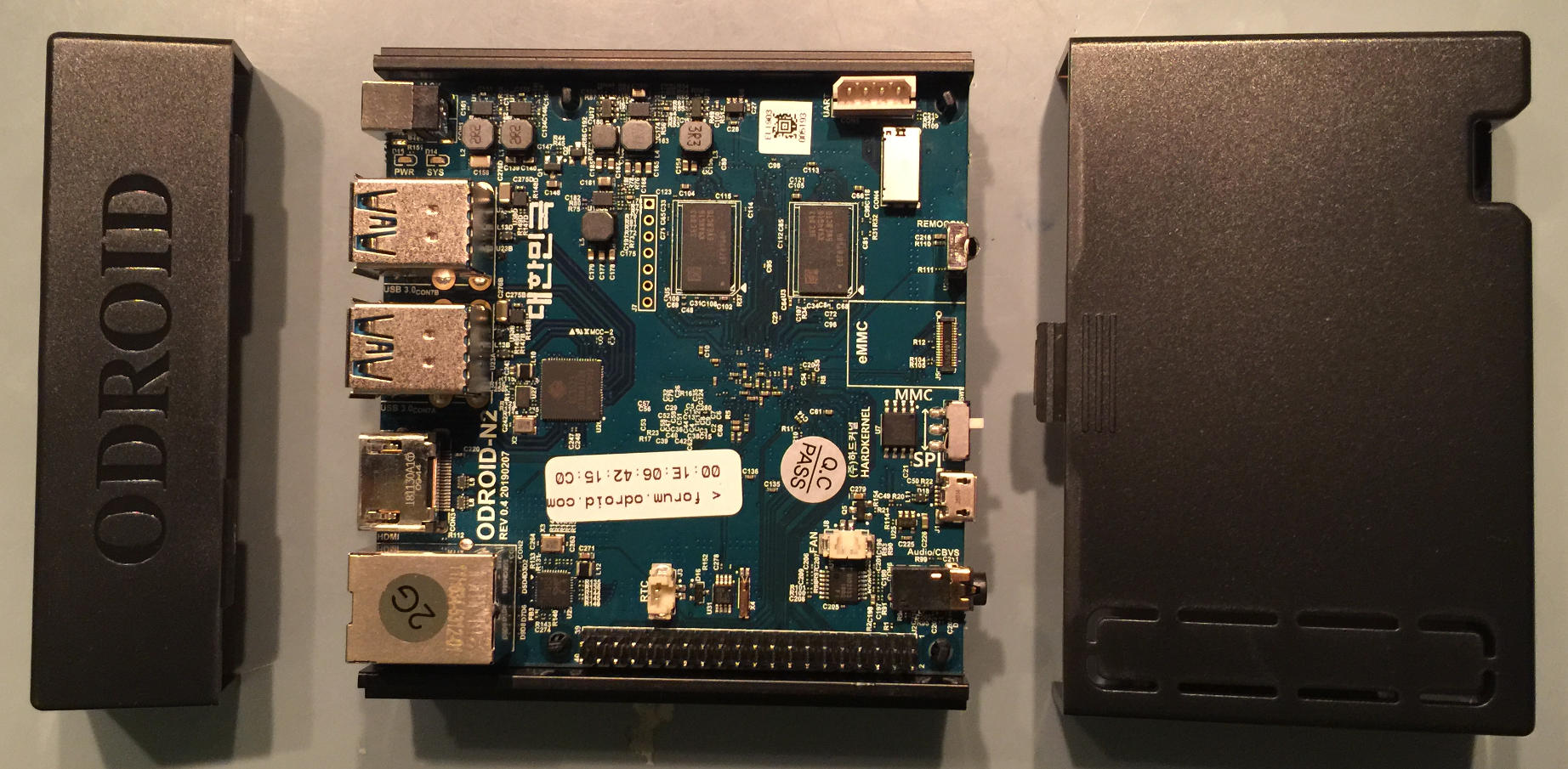
In this step we will put together the ODROID-N2 and get it ready to create our custom boot eMMC or microSD memory module. Seating the single board computer and assembling the case is very simple. This is one of the best case designs I have seen in a while. You will not be pushing and pulling and hoping you do not crack some plastic catches at all. Simply seat the ODROID-N2 on the metal base of the case. This also acts as a heat sink, ingenious! Gently tighten up the screws until they are firmly tight, do not over tighten them. A good firm setup is what we're looking for here. Let us take a look at the case and board.
Next slide on the case front. Make sure you have the case front plastic guides lined up with the little metal ridge on the case bottom.
Now if you have opted to purchase two ODROID-N2 cases then you will want to break out the small GPIO panel on the top of the case's back. This is the longer case top that has a long "door" on it. This will allow you to work on the GPIO section of this tutorial with a protected ODROID-N2. If not, do not worry, we will just leave the remaining case top off for now. Be sure not to have any drinks or cats around your ODROID-N2 while it's exposed. We recommend that you purchase a bootable microSD card from Hardkernel and use it to create the custom Linux OS we will be using in this tutorial series. When I say custom I only mean that we can choose which version of Linux OS images available for the ODROID-N2 we want to use and we will also get experience building bootable eMMC modules and microSD cards.
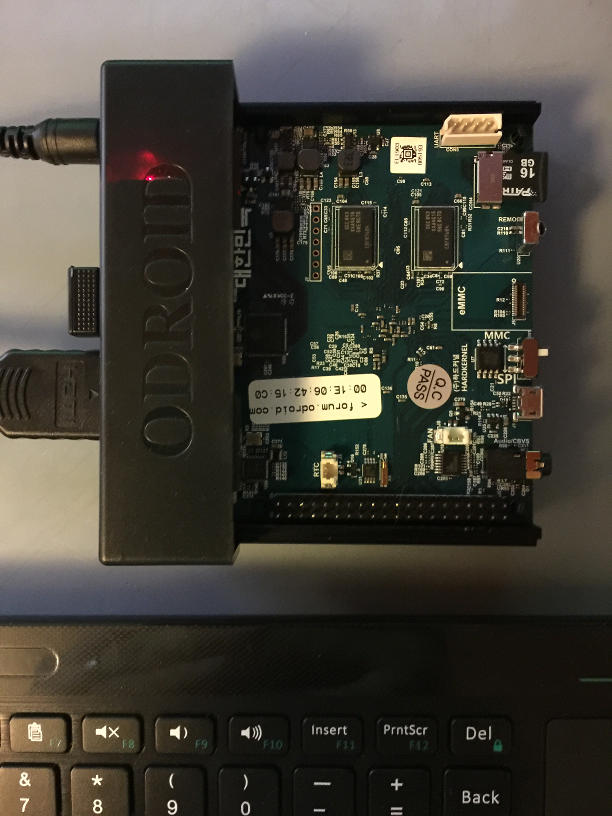
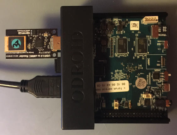
The picture above shows the ODROID-N2 with a Hardkernel bootable microSD card and the boot device switch set to the MMC setting. Note that the MMC setting is used for both eMMC modules and a microSD card. The board gives higher priority to eMMC modules than microSD cards. In this way if you have both setup it will always try to boot the eMMC module first. I'd like to reiterate that we're purposely creating our own bootable eMMC module or microSD card because we want to be able to do so any time we want. Obviously we already have a bootable microSD card, the one from Hard Kernel, but we're only using it as a jumping off point to using the ODROID-N2 for creating our own bootable media. Now that we have the computer setup let us fire it up and get into our Linux desktop. We will be locating and downloading a specific Ubuntu Linux image to write to our eMMC module or microSD card, whichever path you decide to take. If you have access to a computer and are not building your custom boot memory module on the ODROID-N2 just follow the steps using your favorite browser and I will be sure to show you how to write to your storage device of choice on Windows or Mac.
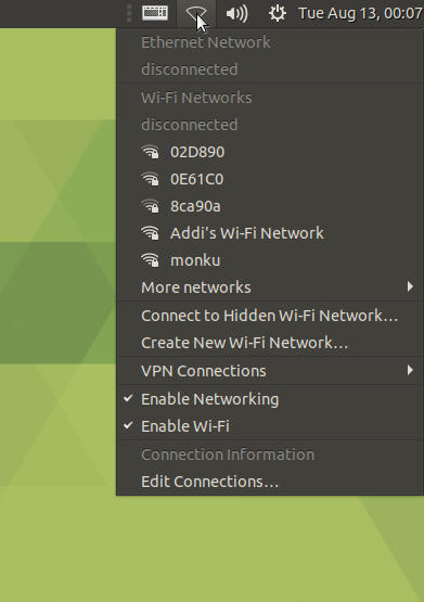
You will need an internet connection for this part. If you do not have access to an internet cable to plug into your ODROID-N2 then purchase a WIFI module, links above, and you should be all set. If you're not sure which one to get just load up the page for that product and see what types of WiFi each module supports. I have found that the cheapest, WiFi Module 0, works just fine and does not take up a lot of space around the ODROID-N2's USB ports. Simply plug the module into an available USB port while you have your system booted up and running Ubuntu MATE. You should be able to select the WIFI icon in the top right corner of the screen. Doing so will give you a list of available WIFI networks in your local environment.
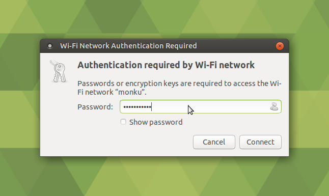
Select your WiFi network and you will be prompted to enter in any authentication information required by the WiFi end point. The screenshot below depicts a similar prompt you will encounter when connecting to WiFi.
Now that you have got your internet connection configured, open up a browser and make sure you can access the internet.
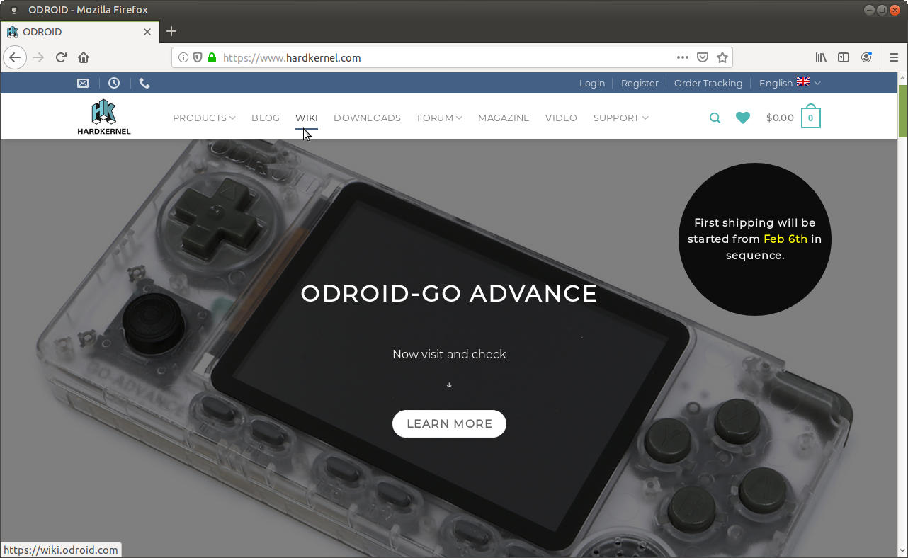
Click the wiki link at the top of the page.
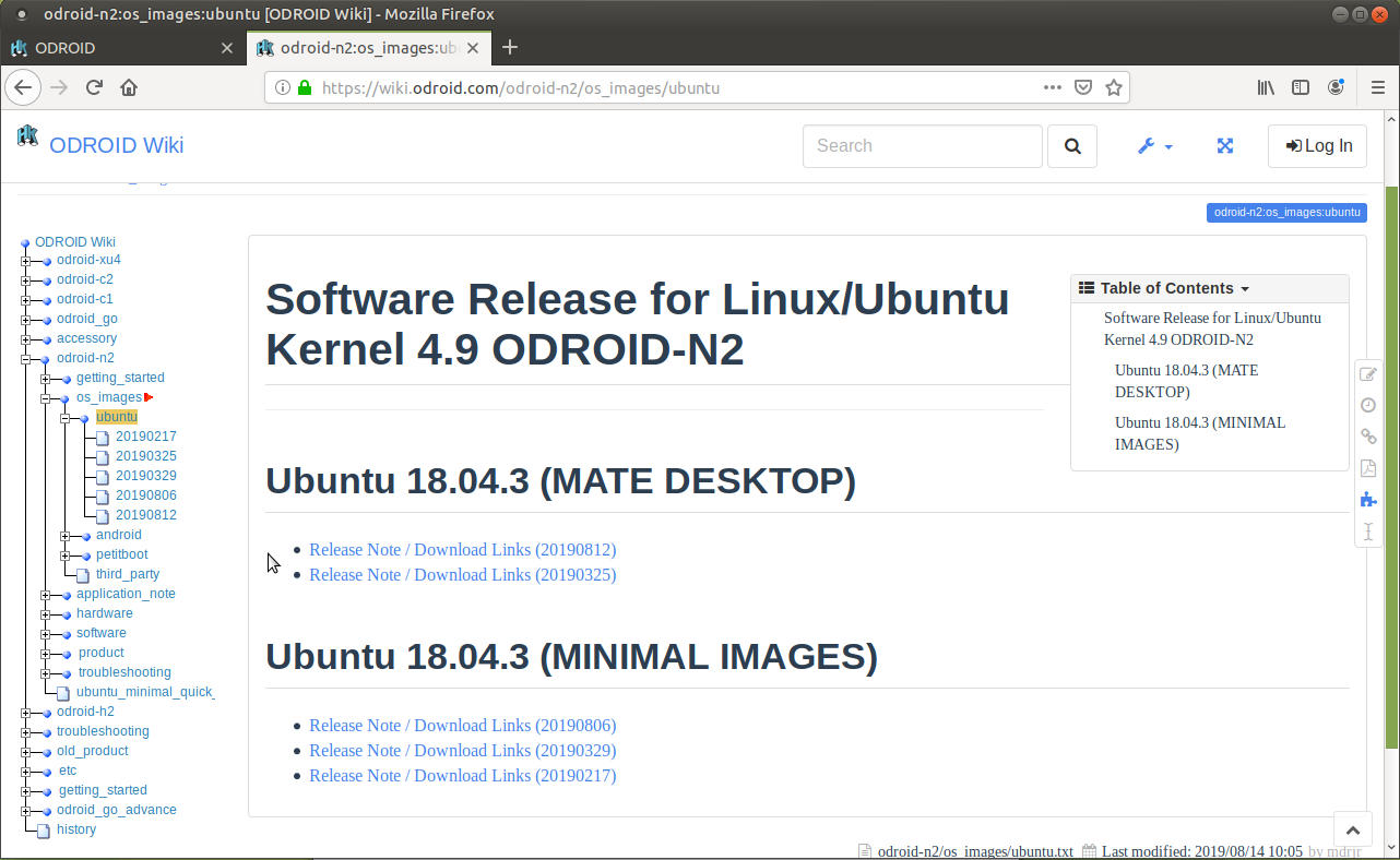
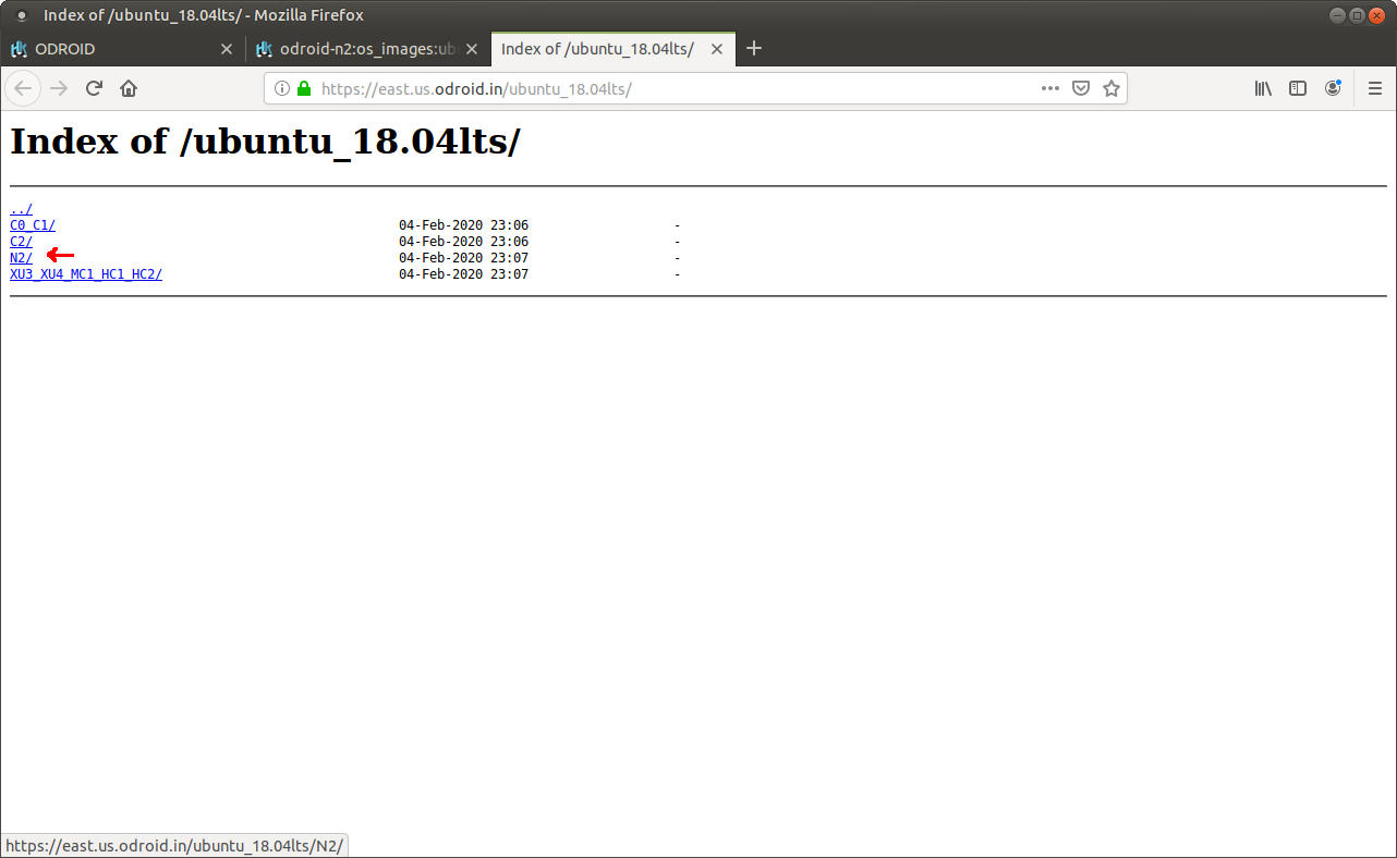
Or you can jump right to the destination by navigating your browser to the ODROID Wiki (https://wiki.odroid.com/). Select the ODROID-N2 option from the side navigation bar. Select os_images then select ubuntu. You should see a list of dates, click the 20190812. Choose a mirror from the list of mirror sites, I use the East Coast Mirror (https://east.us.odroid.in/ubuntu_18.04lts/) because it is closer to me. Once on the mirror site you will have to navigate to the ODROID-N2 OS image, click the ODROID-N2 link.
Next click the ubuntu-18.04.3-4.9-mate-odroid-n2-20190812.img.xz link. It may take a few minutes for it to download because it is around 1GB in size so get up, stretch, walk the dog, feed the cat, or do whatever it is you want to do to kill a few minutes.
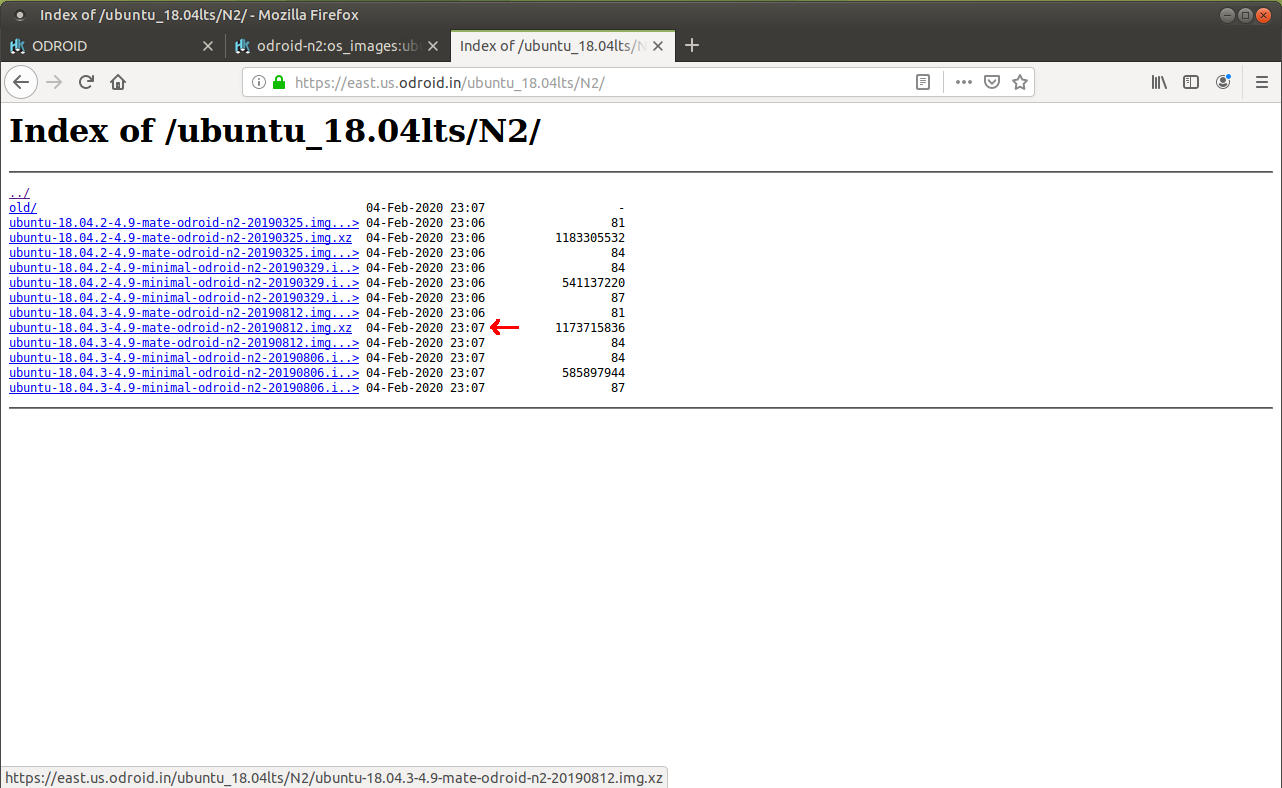
Also, like any good cooking show we have the meal we are making already prepared so a direct link to the east coast mirror OS image we want is, ubuntu-18.04.3-4.9-mate-odroid-n2-20190812.img.xz. Once your download has completed you may receive a window popup like the one shown below. This has something to do with Ubuntu MATE detecting the file type and thinking you want to update your current eMMC module or microSD card.
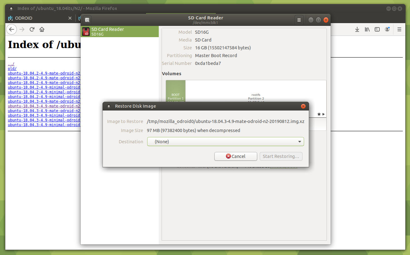
Select Cancel and close the window behind it so that you're back at the browser. Now that you have got a copy of the OS image downloaded it's time to move onto the next step. Read below to choose your path, the recommended path has the best performance and reliability but may be slightly more expensive. Choose wisely.
- If you have a bootable Hardkernel microSD and plan to use an eMMC module (recommended) then proceed to Section 4.
- If you have a bootable Hardkernel microSD and plan to use a microSD card then proceed to Section 5.
- If you have a computer and are building an eMMC module or microSD card: Follow along with Section 4 for eMMC modules, or Section 5 for microSD cards and you will find information on how to build the boot memory module using Windows or MacOS at the bottom of that section.
Setup your ODROID-N2 with an eMMC Module
To prepare for this step you will need your eMMC module and a Hardkernel eMMC to USB adapter. Lay your eMMC module down on a dry static free surface so that the chip side is facing up.
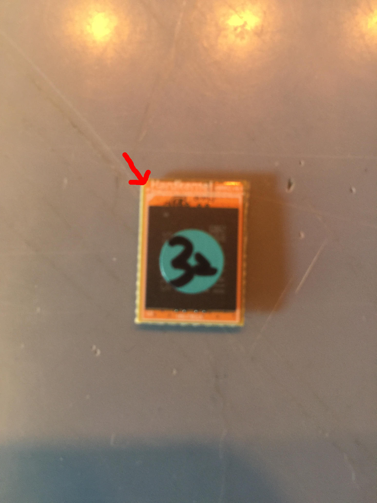
Note the white notch in the corner of the eMMC module. This will line up on the same side, left or right, as the white circle (or notch) on the eMMC to USB adapter. It does not line up with the exact corner just the side.
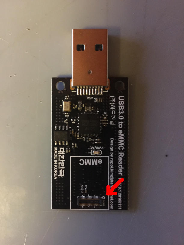
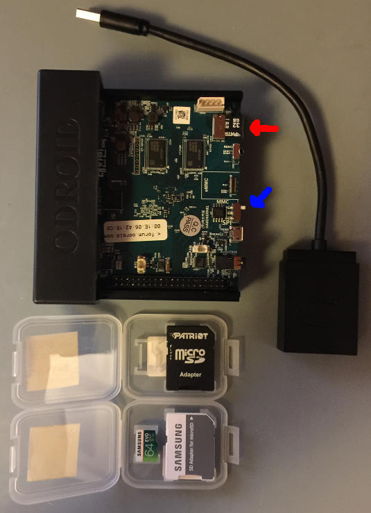
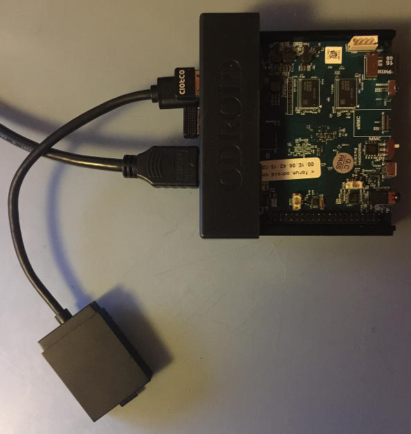
Carefully place the eMMC module's little black connector onto the eMMC to USB adapter's little black connector. You can kind of roll the eMMC module onto the adapter and line up the connectors. Gently press down and the two connectors will gently and slightly snap together. that is it, you have successfully mounted the eMMC module onto the adapter. Now plug your eMMC to USB adapter into your ODROID-N2, as shown below.
You are now ready to start writing an OS image to the eMMC module, which we will cover in the next few steps. Feel free to skip any microSD steps that do not apply to you. You can always come back and look up any info you need. I will cover a few different ways to write the OS image to the memory module using different environments. The process is the same for an eMMC module or a microSD card.
Setup your ODROID-N2 with a microSD Card
To prepare for this step you will need your target, new, bootable microSD card and a microSD to USB adapter. Simply plug your microSD card into the USB adapter and then plug the adapter into your ODROID-N2.
That is it! Now you're ready to start writing an OS image to your microSD card. I will cover a few different ways to write the OS image to the memory module using different environments. The process is the same for an eMMC module or a microSD card.
Writing to your Memory Module using Linux, Windows, or Mac
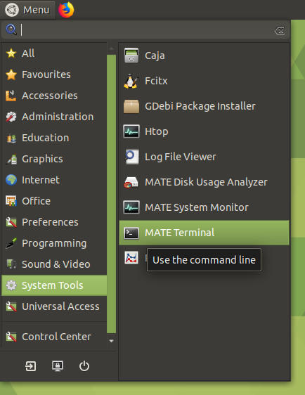
This step will cover writing to your eMMC module or your microSD card. At this point the process is the same for both. If you have connected your eMMC module or microSD card, please eject it. We are going to get the device in Linux for the memory module and we want to be able to detect that new device so we do not accidentally write to our Hard Kernel bootable microSD card. For this step you are going to need to open up a terminal. On the top left hand side of the screen bring up the list of applications, and utilities. Click on System Tools, then locate the MATE Terminal program entry as depicted below. Click it and you will have a terminal window to work with.
In the terminal type the following command:
$ sudo fdisk -lNote the list of drive devices that are shown. Now connect your memory module and run the command again. Note the new entry in the list and write it down or copy and paste it into a text document. This step verifies that we will be writing to the proper memory module. For the purposes of writing this tutorial let us assume that the device is dev/sdx. Next we will unmount the device by using some sweet terminal commands. Unmount the partitions by running:
$ sudo umount /dev/sdx*It may give an error saying the disk is not mounted - that is fine. Now we will write the contents of the image file onto the SD card by running the following command.
$ sudo dd bs=1M if=/path/to/file/your_image_file_name.img of=/dev/sdxIf your file has a .img.xz extension instead of a .img extension you can right-click the file in MATE using normal file operations and extract it to a .img file. You can also use the following command to do both operations in one step.
$ sudo xz -d < /path/to/file/your_image_file_name.img.xz - | \
dd of=/dev/sdx
Remember in this case the /path/to/file/your_image_file_name.img.xz or /path/to/file/your_image_file_name.img is the path to the ubuntu-18.04.3-4.9-mate-odroid-n2-20190812.img.xz file we want to write and /dev/sdx is the device name we figured out earlier. You can navigate to where the file is located using the MATE desktop. Right-click the window and select the Open Terminal command to open a terminal at the location of the target file. In this case your terminal commands would be:
$ sudo dd bs=1M if=your_image_file_name.img of=/dev/sdxor
$ sudo xz -d < your_image_file_name.img.xz - | dd of=/dev/sdxLet the operation run to completion and you will have a fresh new bootable memory module to use on your ODROID-N2. What is more you can use these steps to try different ODROID-N2 operating system images. Just look around the wiki page (https://bit.ly/3a0xyXe) for other OS options to try. For our purposes we are ready to move onto the next step of this tutorial. I will take a moment to demonstrate other ways to write the image to the memory module. It is important to note that the eMMC module and the microSD card behave the same at this point. Linux just views them as a memory device to write to.
If you are working on your ODROID-N2 you can use a gui method to write the image to your memory module of choice. Once the image file has finished downloading find the file in your Downloads folder and right-click on it.
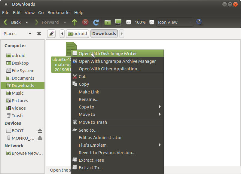
Select the Open With Disk Image Writer option. You should see a window pop-up similar to what is shown below.
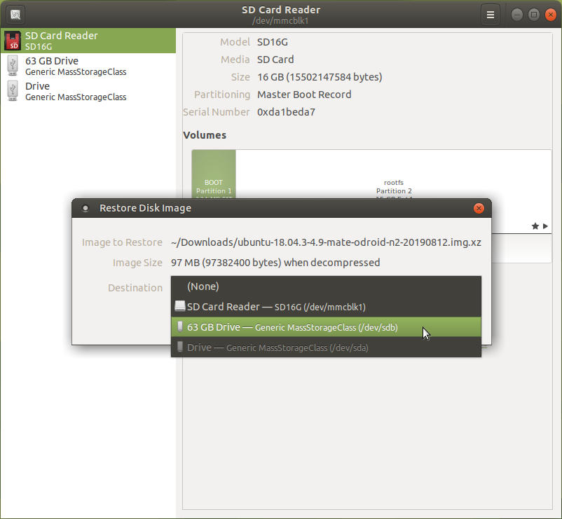
the proper destination to write the image. ALERT: Be very careful here, make sure you are choosing the target memory module and not the boot SD card!
Writing an OS Image on a Mac
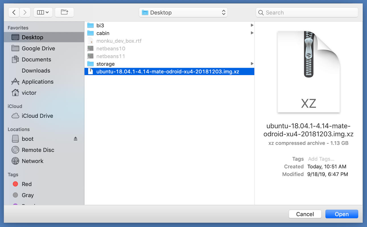
To write the OS image file on a Mac we recommend getting a great piece of free software, Balena Etcher (https://www.balena.io/etcher/). You could also probably run the Linux commands listed above in a terminal on a Mac but let us try something new. Download and install Balena Etcher. The software handles writing .img.xz files so you do not have to worry about decompressing the OS image. Locate your OS image file.
Note: The screenshots below show a different file being written then the one we are working with. The process is the same, no worries.
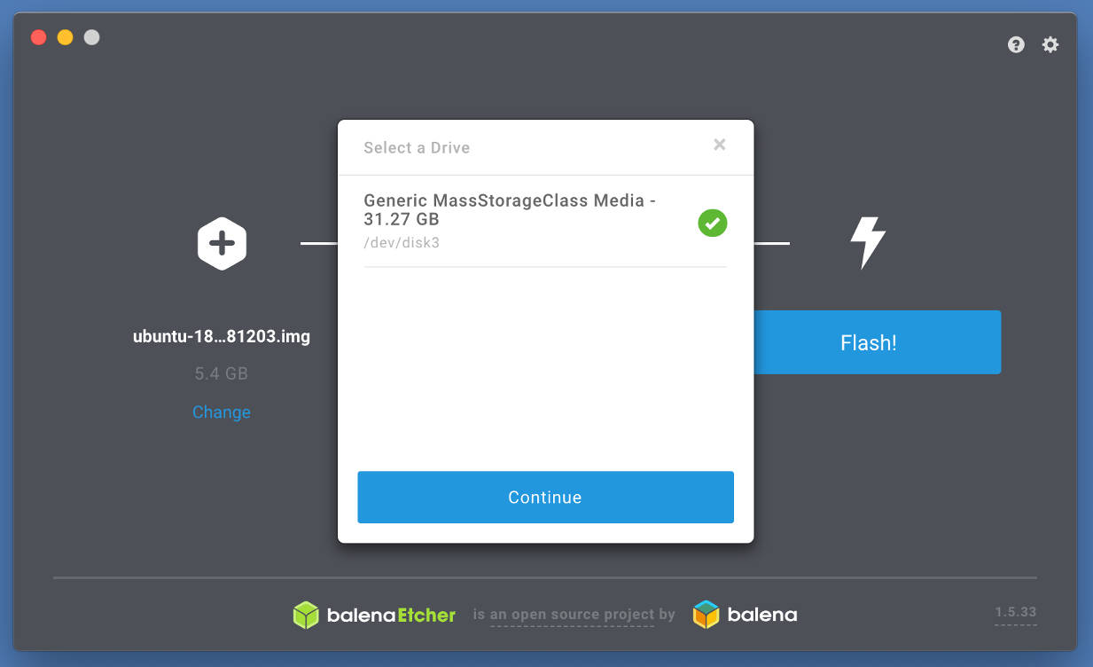
Next, fire up Balena Etcher and answer any prompts for higher privileges that might pop up.
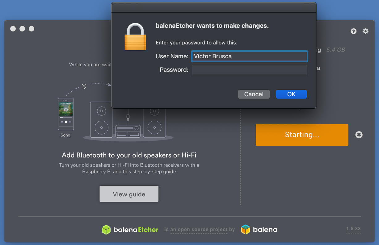
Double check that you are indeed flashing the correct device and that it is the correct approximate size!!
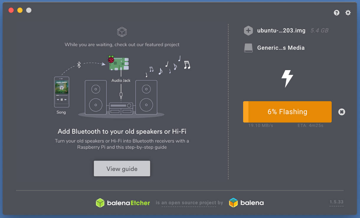
Start flashing the device and wait for the process to complete.
Writing an OS Image on Windows
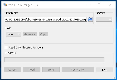
To write the OS image file on a Mac we recommend getting a great piece of free software, Win32 Disk Imager (https://bit.ly/2VqBCMa). Now if you are running Ubuntu Linux under Windows 10 you could also probably run the Linux commands listed above in a terminal. You could also install the Windows version of Balena Etcher and follow the directions for that software listed above. I want to show you a new way so that you have a bunch of options and tools you can use to make your own bootable memory modules. You will have to decompress the .img.xz file before we can write it to the memory module. Get a free copy of 7-Zip (https://www.7-zip.org/). Install it and use it to decompress the .img.xz file you should have a nice fresh .img file in a few minutes.
Once your .img file is decompressed and ready to use, open up Win32 Disk Imager and navigate to the .img file you want to write to your microSD card. ALERT: Be sure to select the proper drive letter to write to!! If you have any doubts just eject the microSD card and take note of which drive letters go away. Any card, especially if it has a bootable OS in it, will mount as two drive letters. It is ok to simply choose one of them. The screen shot below shows Win32 Disk Imager in action, it is being used to write a different .img file, just ignore that part.
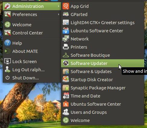
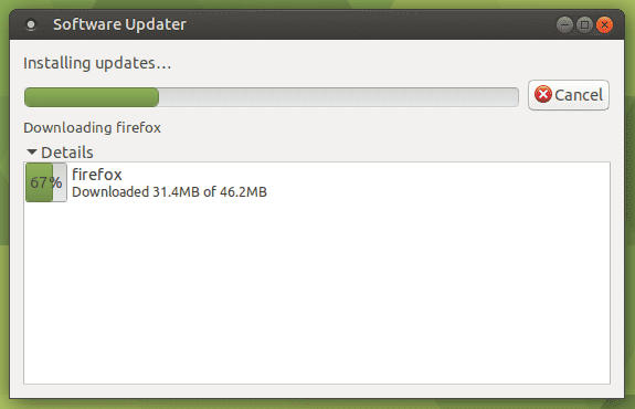
Once you have everything setup click the Write button at the bottom of the window and let the software do its thing. Be careful that you click the correct button. It can become confusing at times which direction the read or write operation is going, especially if you have done a few cards in a row using different operations. There will be some hint text that will explain what the button you're about to click does. I always read it and double check that it is indeed what I want to do. Configuring Your Dev Environment Now that we have created a new custom bootable eMMC or microSD memory module, whichever you choose, we have to update the OS and install some software before we can begin developing. Boot up the ODROID-N2 with your new memory module and put the Hardkernel bootable microSD card in a safe place. First let us update the operating system and software. We will do this two different ways. The first will use the MATE desktop system tools. Find the Software Updater tool under Menu -> Administration -> Software Updater.
Click the Update button and let the process complete. Sometimes an update may require you to hit a button so it's a good idea to keep the window visible and also have the details visible. You should see a window like the following while the update is running.
Once that is complete we will run an update from the command line. This step is more or less the same thing as what the system update tool is doing but it is good to know how to run an update from a terminal so let us do it. Open up the terminal like we did earlier in the tutorial and run the following commands. The default superuser password is odroid. Copy and paste the following command in the terminal window and hit enter.
$ sudo apt-get update -y; sudo apt-get upgrade -y; sudo apt-get \
autoremove -y;
Once that is done we will want to install some software and we can get most of it done right from the terminal. We're going to install gparted, for partition and drive management, gimp, for image management, default-jre, so we can use the Java runtime environment, and chromium-browser, to add a Chrome browser to the system. Copy and paste the following command in the terminal window and hit enter.
$ sudo apt-get install gparted -y; sudo apt-get install gimp -y; \
sudo apt-get install default-jre -y; \
sudo apt-get install chromium-browser -y;
The next piece of software we need to install is a great Java IDE, https://www.netbeans.org. Fire up your browser and navigate to the netbeans website (https://www.netbeans.org).

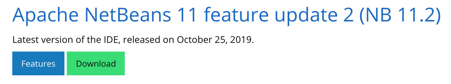
Click the download button and you will be brought to a screen with a list of versions. Go to the latest stable version and click the download button as shown below.
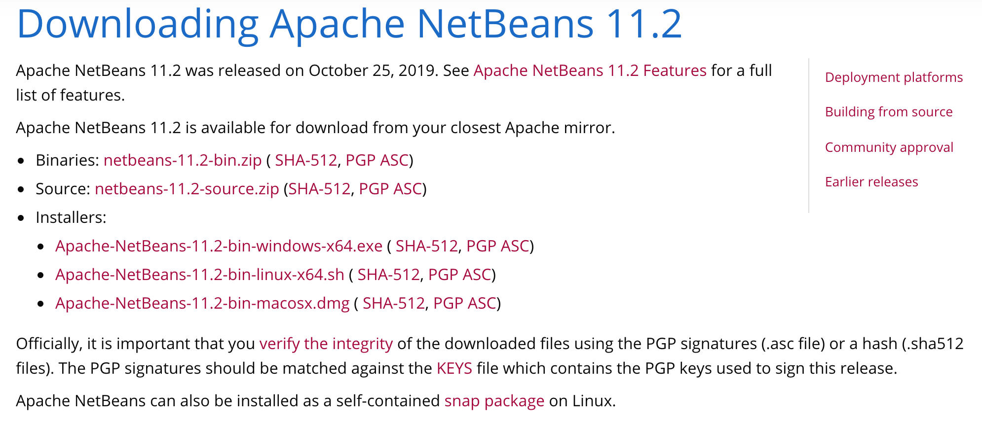
This will take you to a page with a few different links for the version of netbeans you selected. We will want to download a zipped version of the binary files. Click the binaries link and let the IDE download.
Go to the Downloads folder and copy and paste the zip file into a new folder named install_zips, create this folder in your home directory. Once the file is done copying over, unzip it by right-clicking the compressed file and selecting the unzip menu option. Create another new folder in your home directory named applications. Move the uncompressed version of netbeans into this directory. Open the folder, find the bin folder, open it, and right-click on the file named netbeans. Choose the “pin to desktop” option. Now we have a link to open our netbeans IDE. But wait, it looks, well rough. Let us grab a good looking icon for it. Navigate your browser to https://commons.wikimedia.org/wiki/File:Apache_NetBeans_Logo.svg. Save the netbeans icon file from the page that loads up.
Figure 28 ]
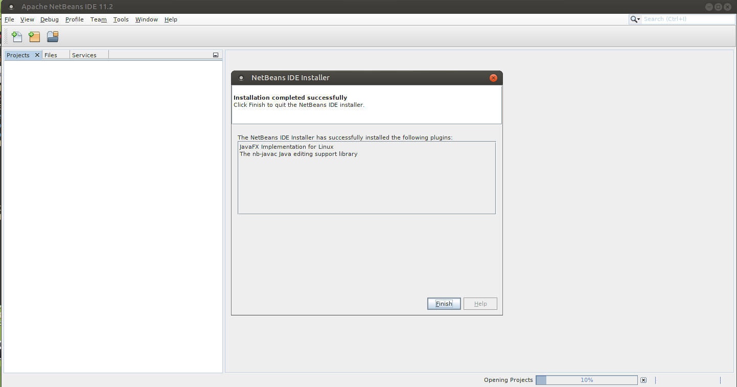
Right-click on the desktop shortcut for netbeans. Click on the icon and find the new netbeans icon you just downloaded. Choose it to be the icon for the desktop shortcut. Now we have a proper looking IDE shortcut. Open up the netbeans IDE and allow the IDE to install any modules it needs. You may also have to do this when opening a new project for the first time, simply allow the IDE to install the modules it needs.
Setting up a Swap Partition
In this step we will turn on a swap partition and set up our ODROID-N2 to always enable swap space on boot. This can help us with the IDE and other memory needs we will have when writing games for the ODROID-N2 on the ODROID-N2. First we will check if we have any swap space enabled. Run the following command in the MATE Terminal, Menu -> System Tools -> MATE Terminal. You may want to right-click the menu option and click pin to desktop so that you have a quick shortcut to the terminal when you need it.
$ sudo swapon --showIf there is no text displayed you do not have swap space enabled. If you do see some information printed then you have swap space enabled and you can skip the rest of this step. Create a new swap file on the root of the boot drive by running the next command.
$ sudo fallocate -l 1G /swapfileSet the permissions on the swap file to be secure.
$ sudo chmod 600 /swapfileEnable the file as a new swap file.
$ sudo mkswap /swapfileTurn on the swap file.
$ sudo swapon /swapfileTo enable the swap file on every boot edit the fstab file and add the following entry, like so.
$ sudo nano /etc/fstabCopy and paste the following line at the bottom of the file's current contents.
/swapfile swap swap defaults 0 0Give the system a reboot by running the following command, sudo shutdown -r now, and bam! We now have an active swap partition. When the system comes back up you can check that the swap file was enabled by running, sudo swapon --show. You should see an entry print out after running the command. If not, go through the process again and make sure you run the correct commands in order.
Mapping Specific GPIO Pins
In this step we will use the terminal and our breadboard to figure exactly what number the GPIO pins, as they are expressed on the breadboard, are. Now sometimes you can check the documentation to see where each pin is, but depending on the OS and how it works you might find yourself in a situation where the pin numbers aren't matching the documentation. Plus it's fun to hook up an LED to the ODROID-N2 and get the light to blink.
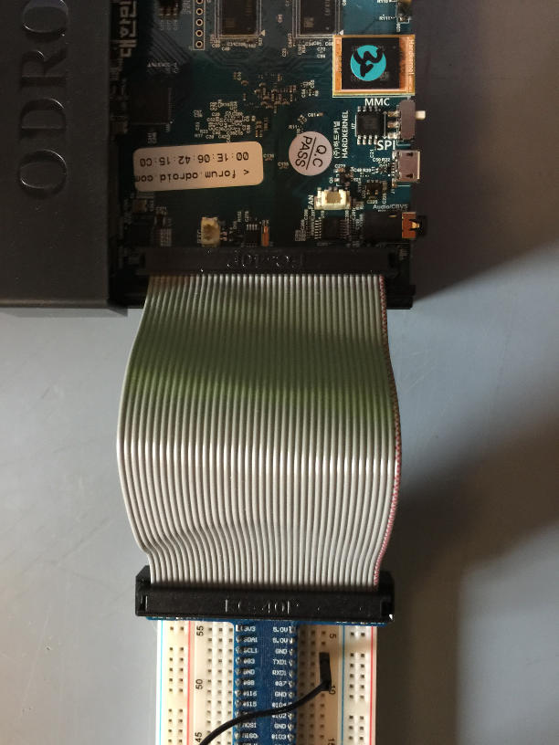
Now you will have to connect your breakout breadboard to the ODROID-N2. Simply plug the connector onto the GPIO expansion pins on the board. Make sure it is facing the correct way, the red stripe on the ribbon cable should line up with the side of the GPIO pins that have labels 1, and 2.
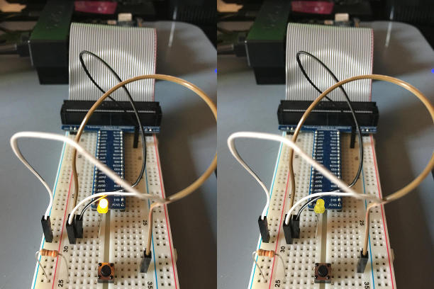
We are going to setup a simple circuit using 1 resistor, 1 LED, and 3 jumpers using the breakout breadboard tinker kit from Hardkernel. We're going to setup the following simple circuit. Follow the image and diagram below. Your pin may be different. I'm using pin number 488 which maps to position 7 on the breadboard.
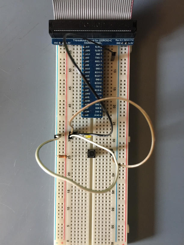
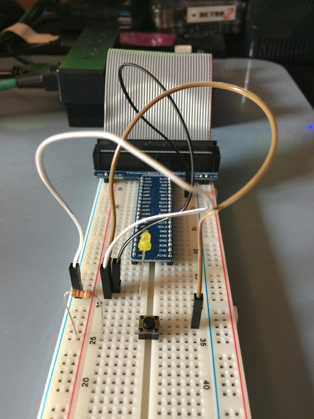
A simple circuit diagram is as follows. The circuit serves two purposes. One, it allows for the pin voltage to drive the LED. This is handled by the first branch of the circuit. Two, it allows for the pin voltage to be driven by a button. This is used to mimic input from a gamepad.
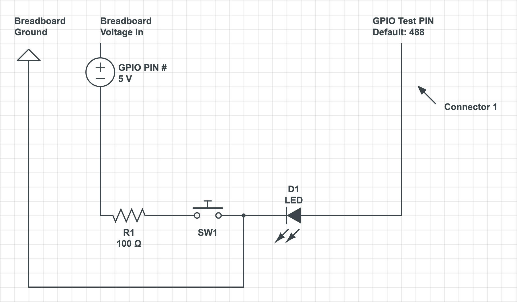
Follow the images and diagram and set up a similar circuit on your breadboard. Once it is ready we're going to run a script to locate some workable pins. Download the following GPIO scripts (zip) file, https://bit.ly/32vO2Ek. It has multiple scripts for working with the GPIO pins. Once the file download is completed, decompress the zip file and move the btn_test, btn_prep, and pin_finder scripts into the home directory. Clean up the download folder by moving all the zip files into the install_zips folder we created earlier. This will give you a backup of all the files you need for this tutorial. Next we are going to query the GPIO pin files to get an idea of what numbers our Linux OS has assigned to the pins. This will give us a range to work with. We're going to be running some tests to figure out which pin is associated with what GPIO number. Run the following command to see the GPIO pin numbers.
$ sudo ls /sys/class/gpio/You should see certain numbers next to the GPIO chips found. These indicate starting pin numbers and can be an indication of a pin range.
/sys/class/gpio/gpiochip64/
/sys/class/gpio/gpiochip128/
You will see different numbers but what they indicate is a range of pin numbers from 64 to 128 and possibly from 128 up to some unknown number. This will give you an indication of what GPIO numbers to use when you start looking for matching pins. Now, open a terminal and run the following command from the home directory, nano pin_finder. All the files are setup to work with pin number 488 by default. This may work for you but you should still complete these steps so you know how to find more of your own pins. Edit the text at the top of the file, TMP=488, and change the number to one of the numbers in the range you identified previously. Or you could just move up one to 489 and try that. Write and save the file, Ctrl + O + ENTER, followed by Ctrl + X. Run the script with the following command.
$ sudo ./pin_finderThe script will toggle the high and low value of the target pin. Move connector #1 from pin to pin, waiting for 2 seconds at each spot to see if the LED flashes. If it does you have found the pin location that matches the Linux GPIO pin number.
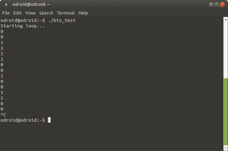
When you find one blinking pin, write down the position on the breadboard and the pin number used to find it. Make sure to exit the pin_finder script with Ctrl + C when the LED is off. If you miss the timing just start the script and try again. Open the btn_test with the command, nano ./btn_test. Edit the line at the top of the file and enter in the number of the pin you have found. Write the file and exit with Ctrl + O followed by Ctrl + X. Run the btn_test script like so, sudo ./btn_test. While the script is running, toggle the push button and you should see the output change from 0 to 1 and the LED turn on and off. The image below shows the terminal output during this process.
Setting up a Service for GPIO Permissions
In this step we will quickly setup a service in Linux that will open up the GPIO pin you have located to the odroid user so that we do not have to type sudo every time we want to use it, and so that our Java program can access them also without being required to run the sudo command. Edit the btn_prep script using nano as we have done before. Change the number at the top of the script to the GPIO number you located with the pin_finder script. Open a terminal and run the following commands to set the permissions for the GPIO button prep files. You should have a file named btn_prep and custgpiosvc.service in your home directory.
$ sudo chmod 755 ./btn_prep
$ sudo +x 755 ./btn_prep
$ sudo chmod 755 ./custgpiosvc.service
Next we will copy the btn_prep script to the /usr/bin/ directory. Run the following command in the terminal. Make sure you are in the home directory. If you need to get back to the home directory run these commands,
$ sudo cp ./btn_prep /usr/bin/Now we will install the systemd service so that our system will set permissions to the GPIO files so that the odroid user can access them without running the sudo command. This will make things easy for us to access the pins from Java.
$ sudo cp custgpiosvc.service /etc/systemd/system && sudo systemctl start custgpiosvcCheck to see if the service is up and running with the following command:
$ systemctl is-active custgpiosvcYou should see the word “active” as output. To run the service each time the system boots up you will have to run, systemctl enable custgpiosvc. Now give the system a reboot, sudo shutdown -r now.
Setting Up Projects in Netbeans
In this step we will load up the Java project we need into the Netbeans IDE and make some slight configuration changes. First download the version of the project we will need for this tutorial. This project will be updated and different as the tutorial series proceeds so expect to download a similar project file in the future if you follow along.
Netbeans IDE Project v0.5.0 (https://bit.ly/2w7i70z)
The project includes a lot of Java files and we will go over them in a future tutorial but we're going to focus on a small project for interacting with the ODROID-N2's GPIO pins. I will do a more in depth review of code in an upcoming tutorial. And we will go over the game API, also in an upcoming tutorial, because we're going to be working with it to build some games!
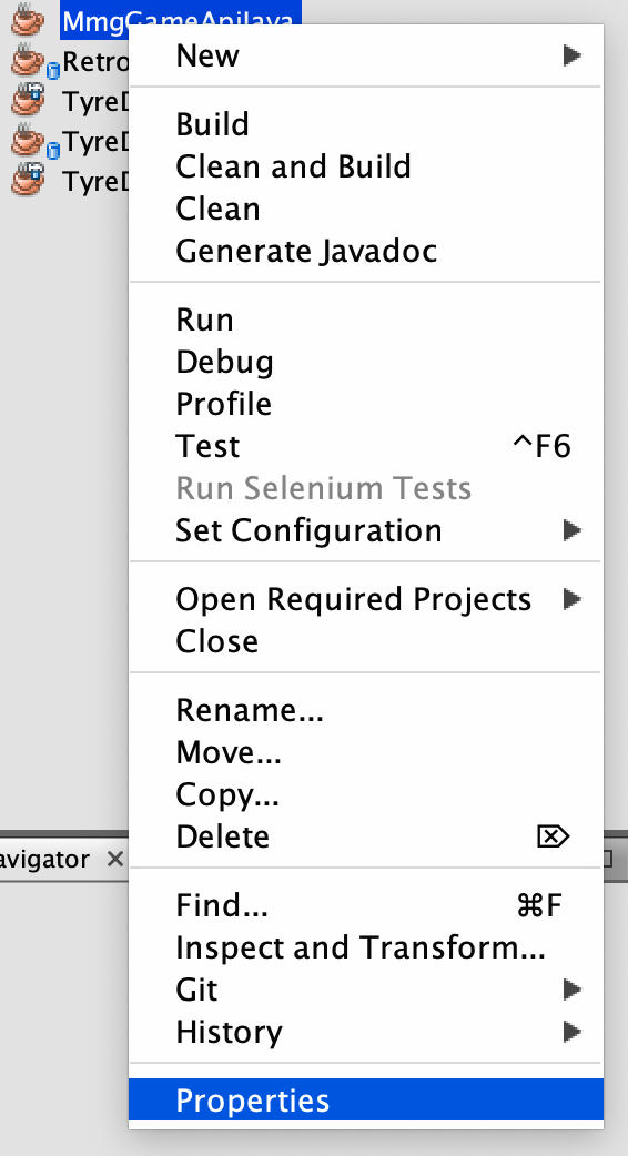
Unzip the project after it finishes downloading. Copy the original zip file to the install_zips folder. Move the resulting project directory to a new folder in your home directory. Name the folder netbeans_projects. Now fire up netbeans and open the project by clicking the File -> Open Project menu option. Navigate to the netbeans_projects folder you created and choose the MmgGameApiJava_v0-5-0 folder. The project will load up in netbeans, allow netbeans to install any necessary modules if it pops up and asks to do so. We are going to make sure the project has one slight configuration change. Right-click on the project and select the properties option similar to what is shown below.
Make sure that the Build -> Packaging -> JAR File property is set to the following, dist/MmgGameApiJava.jar as shown below.
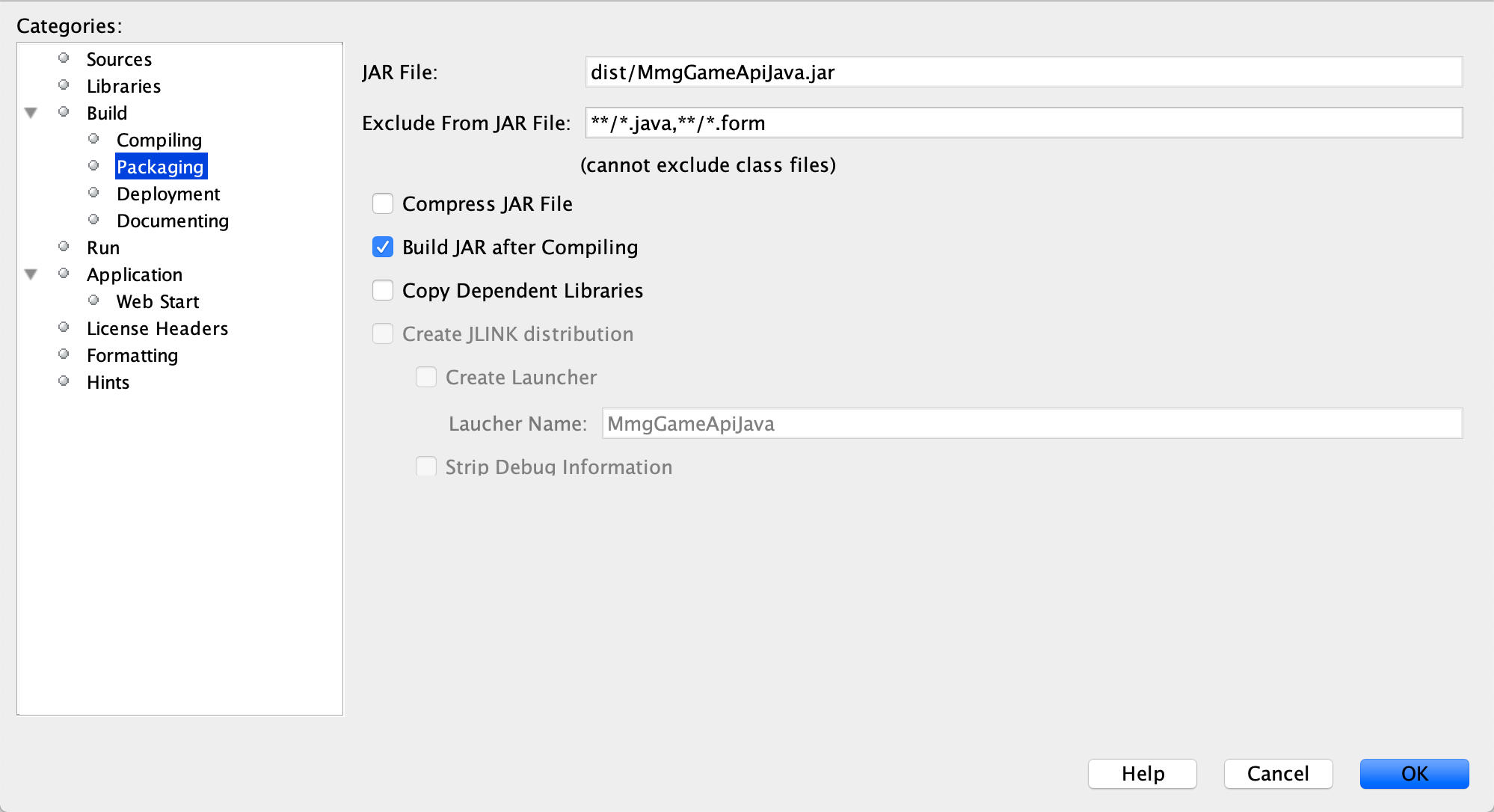
We are all ready to run our Java programs and demonstrate Java connection to Linux GPIO pins! This was a long detailed tutorial to setup our environment. I hope you learned a lot going through it, you have certainly accomplished a ton. We're going to be using this setup to create some Java games for the ODROID-N2 on the ODROID-N2 and use the GPIO pins to control the game with a simple game pad of sorts. This tutorial was the first step.
Reading GPIO Pins with Java
In this step we will tie everything together and read the status of a GPIO pin using Java, very cool. Go to the project you just loaded in netbeans, MmgGameApiJava. Expand the Source Packages section, select the com.middlemind.OdroidGpio package and expand it. Select the OdroidGpio.java file and open it.
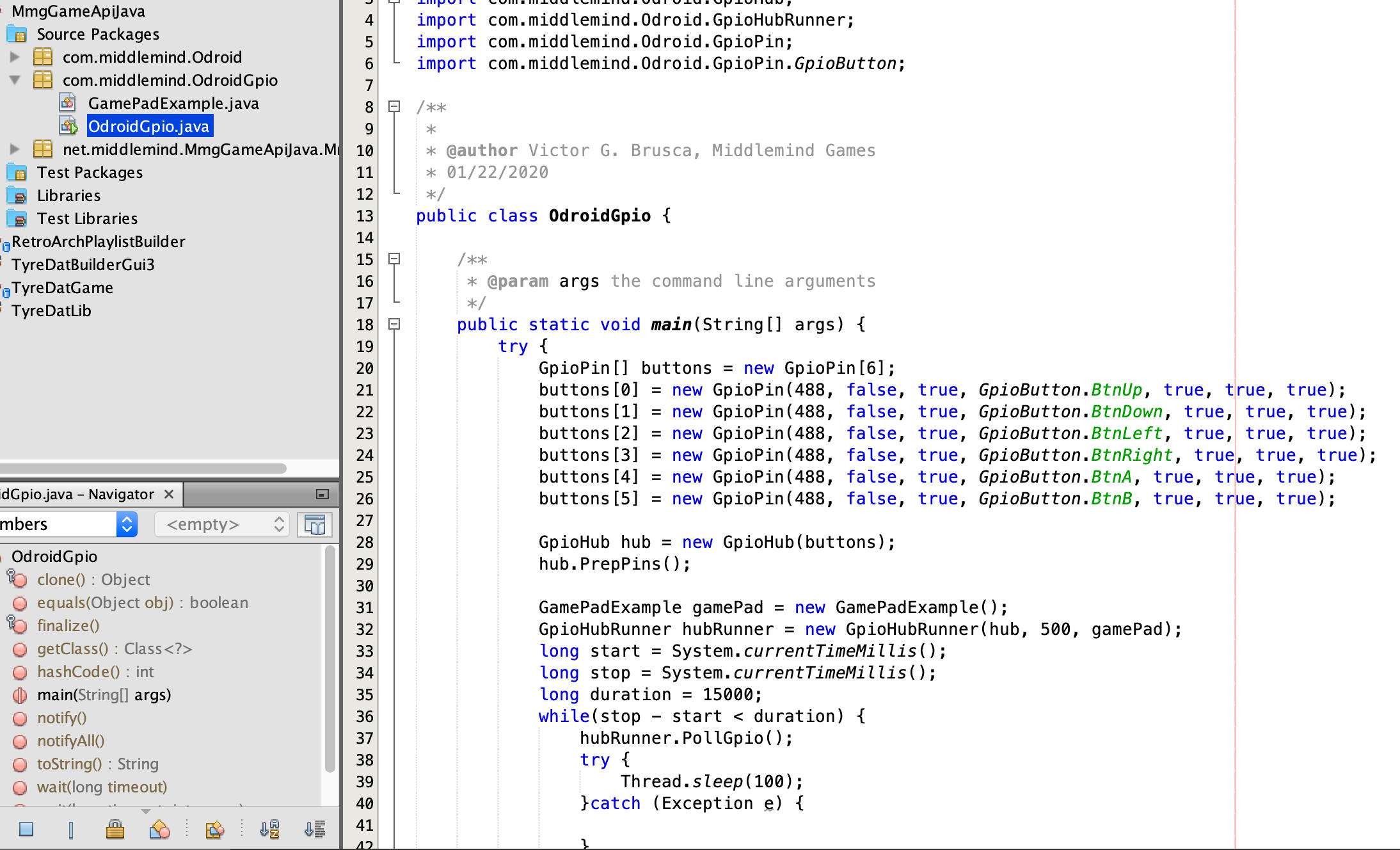
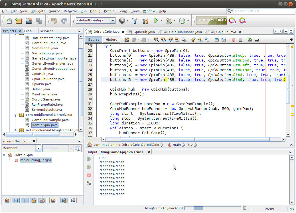
Change the GPIO pin number next to the new GpioPin lines. There are six of them to handle a 4 direction D-Pad and 2 input buttons. For now though, set the first number, 488, to the GPIO pin number you located yourself with pin_finder. Once that is done right-click on the MmgGameApiJava project and select clean and build. Open a terminal and navigate to the JAR output directory using the following command. $ cd ~/netbeans_projects/MmgGameApiJava_0-5-0/dist Make sure there is a new MmgGameApiJava.jar file in the directory by running the command, ls -al ./MmgGameApiJava.jar, in the terminal. Get ready to run the program, while it's running we are going to toggle the LED and see what the Java program does. Make sure your circuit is setup to work with the pin number you chose, check your notes from the pin_finder step. When you are ready, right-click on the OdroidGpio.java file and select Run file, from the menu. While the program is running press the button and hold it for a second or two, you should see ProcessAPress in the output window when the button is pressed as shown below.
That wraps up our first tutorial in this series: reading the status of GPIO pins in Java running on your own personal ODROID-N2 Linux computer. That’s a good start and a great place to end this first tutorial. Stay tuned! Software and Scripts The software and scripts used in this tutorial can be downloaded at the following links. There are also links provided in the tutorial at the step where they are needed. GPIO Scripts (https://bit.ly/2HUJXA1) Netbeans IDE Project v0.5.0 (https://bit.ly/2TguWxy)
For comments, questions, and suggestions, please visit the original article at http://middlemind.net/tutorials/odroid_go/odroid_jgd_0.html.
Be the first to comment