

We will learn how to get the status of the battery with Arduino in this guide. The LCD will display how much battery voltage remains in volts.
We can read the battery level through one of the 12-bit SAR ADCs which are integrated in ESP32. These ADCs are:
- ADC1: 8 channels, attached to GPIOs 32-39.
- ADC2: 10 channels, attached to GPIOs 0, 2, 4, 12-15, 25-27.
There are some restrictions for an application's use of ADC2. The battery is attached to GPIO pin number 36, so we should read a value from that using ADC1. There is a library to control ADC for ESP32 and is called adc.h. In this guide, we're going to use that to read the current battery level in volts and display it on the LCD. First, prepare the code like below to display on the LCD:
#include

void setup() {
// put your setup code here, to run once:
GO.begin();

GO.lcd.setTextSize(2);
}

double readBatteryVoltage() {

}

void showBatteryVoltage(double voltage) {
GO.lcd.clear();
GO.lcd.setCursor(0, 0);

GO.lcd.printf("Current Voltage: %1.3lf V \n", voltage);
}

void loop() {
// put your main code here, to run repeatedly:
showBatteryVoltage(readBatteryVoltage());
delay(1000);
}
We defined two functions in advance:
- readBatteryVoltage(): returns completely calculated voltage.
- showBatteryVoltage(): receives that voltage and print that on the screen.
Set the channel up to the proper values as we designed. Before setting it up, it’s important to know that the GPIO battery voltage is divided by 2 due to the input limitation of the integrated ADC. So, if the original value coming from the battery is 3.7V, then the input value to the GPIO pin will be about 1.85V. Thus, we have to multiply the value by 2 to know the actual voltage.
We use 12 bit SAR ADC for the channel with 11 dB attenuation. We should use these rates to calculate the result as well. First of all, define that extra value as a Preprocessor macro and include necessary libraries to use ADC on ESP32:
- driver/adc.h: to get a raw ADC value about the voltage.
- esp_adc_cal.h: to calculate a correct voltage by using the AP.
Then, set the channel with the proper value by using two functions:
- adc1_config_width(): configures width of the ADC.
- adc1_config_channel_atten(): configures attenuation of the channel. GPIO pin number 36 uses channel number 1.
To get an accurate ADC voltage, calibration is needed. The ADC reference voltage is originally 1.1V by default but actually differs slightly on every ESP32 module. The manufacturer writes the calibration data in efuse:
- esp_adc_cal_characterize(): returns a characteristic of its AP as a structure.
The readBatteryVoltage() function reads an ADC value with the adc1_get_raw() function. It returns a calculated voltage as a double type value using the esp_adc_cal_raw_to_voltage() function:
#include
#include <driver/adc.h>
#include

#define RESISTANCE_NUM 2
#define DEFAULT_VREF 1100

static esp_adc_cal_characteristics_t adc_chars;

void setup() {
// put your setup code here, to run once:
GO.begin();

GO.lcd.setTextSize(2);

adc1_config_width(ADC_WIDTH_BIT_12);
adc1_config_channel_atten(ADC1_CHANNEL_0, ADC_ATTEN_DB_11);
esp_adc_cal_characterize(ADC_UNIT_1, ADC_ATTEN_DB_11, ADC_WIDTH_BIT_12, DEFAULT_VREF, &adc_chars);
}

double readBatteryVoltage() {
return (double) esp_adc_cal_raw_to_voltage(adc1_get_raw(ADC1_CHANNEL_0), &adc_chars) * RESISTANCE_NUM / 1000;
}

void showBatteryVoltage(double voltage) {
GO.lcd.clear();
GO.lcd.setCursor(0, 0);

GO.lcd.printf("Current Voltage: %1.3lf V \n", voltage);
}

void loop() {
// put your main code here, to run repeatedly:
showBatteryVoltage(readBatteryVoltage());
delay(1000);
}
Optionally, we can calculate more accurately by multi-sampling the ADC value.
Read the value 64 times, and divide that by the repetition count.
#include
#include <driver/adc.h>
#include

#define RESISTANCE_NUM 2
#define DEFAULT_VREF 1100
#define NO_OF_SAMPLES 64

static esp_adc_cal_characteristics_t adc_chars;

void setup() {
// put your setup code here, to run once:
GO.begin();

GO.lcd.setTextSize(2);

adc1_config_width(ADC_WIDTH_BIT_12);
adc1_config_channel_atten(ADC1_CHANNEL_0, ADC_ATTEN_DB_11);
esp_adc_cal_characterize(ADC_UNIT_1, ADC_ATTEN_DB_11, ADC_WIDTH_BIT_12, DEFAULT_VREF, &adc_chars);
}

double readBatteryVoltage() {
uint32_t adc_reading = 0;
for (int i = 0; i < NO_OF_SAMPLES; i++) {
adc_reading += adc1_get_raw((adc1_channel_t) ADC1_CHANNEL_0);
}
adc_reading /= NO_OF_SAMPLES;

return (double) esp_adc_cal_raw_to_voltage(adc_reading, &adc_chars) * RESISTANCE_NUM / 1000;
}

void showBatteryVoltage(double voltage) {
GO.lcd.clear();
GO.lcd.setCursor(0, 0);

GO.lcd.printf("Current Voltage: %1.3lf V \n", voltage);
}

void loop() {
// put your main code here, to run repeatedly:
showBatteryVoltage(readBatteryVoltage());
delay(1000);
}
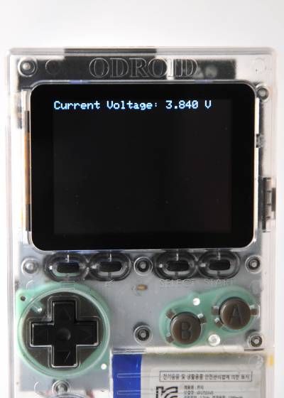
Press CTRL-U to compile and upload the sketch. The current voltage of the battery will be shown on the LCD.
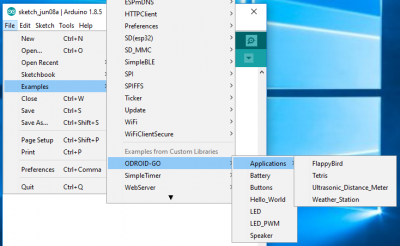
Completed example
The complete example is available by clicking the Files → Examples → ODROID-GO → Battery menu to import and press CTRL-U to compile/upload, as shown in Figure 2.
For comments, questions and suggestions, please visit the original article at https://wiki.odroid.com/odroid_go/arduino/05_battery.
Be the first to comment