GO Green with “Envi”: A Qwiic Environmental Combo Sensor for Your Beloved Game Machine

“Gee, it stinks in here,” you might be thinking. While this statement is a little vague, it does indicate that you could be experiencing an air quality issue within your environment. Most odors, toxic or otherwise, are generally termed as derivatives of volatile organic compounds (VOCs). In fact, a key measurement in determining air quality is the quantification of total volatile organic compounds or TVOCs.

One of the premier sensors for measuring VOCs is the ultra low-power CCS811 digital gas sensor by ams AG in Austria. In addition to providing a VOC measurement, the CCS811 is also able to output equivalent CO2 (eCO2) levels. These eCO2 values are typically a form of VOC that is generated by humans.

Figure 1 - Monitor your indoor environment with an ODROID-GO.

These air quality levels are given as parts per billion (PPB) for TVOCs and parts per million (PPM) for eCO2. As a standalone sensor, the output from the CCS811 is unrefined and inaccurate. In order to improve the air quality measurement output, the CCS811 readings can be improved by compensating them with the input of the current air temperature and relative humidity.

A venerable sensor for providing ambient temperature and humidity is the integrated digital environmental sensor BME280 by Bosch Sensortec. Integrating the BME280 output into the calculations for CCS811 air quality could be a cumbersome task. Luckily, SparkFun Electronics (SFE) has thoughtfully combined both the CCS811 and the BME280 sensors together onto a single breakout board that is able to reliably monitor environmental air quality.

Figure 2 - The SFE Environmental Combo Breakout. Image courtesy of SparkFun Electronics.

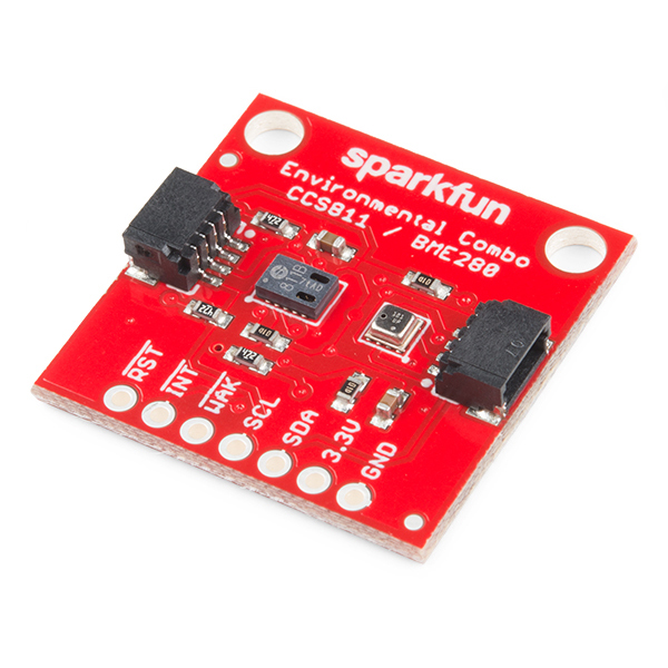
Dubbed the Qwiic Environmental Combo Breakout, SparkFun sweetened the deal further by bundling this air quality monitoring package into their Qwiic I2C ecosystem. Now by utilizing the Qwiic Adapter project that we built in the May 2019 issue of ODROID Magazine, available here, https://magazine.odroid.com/article/go-and-be-qwiic-about-it/?ineedthispage=yes we can easily monitor our indoor air quality with impressive precision via a simple plug-and-GO system. Ah, the sweet smell of success!

Figure 3 - A sample output from the Qwiic Environmental Combo Breakout.

Parts

SparkFun Environmental Combo Breakout – CSS811/BME280 (Qwiic) – SEN-14348 $35.95 Qwiic Cable – PRT-14427 $1.50

Step-by-Step

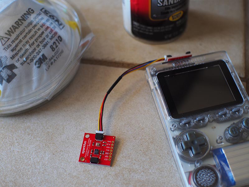
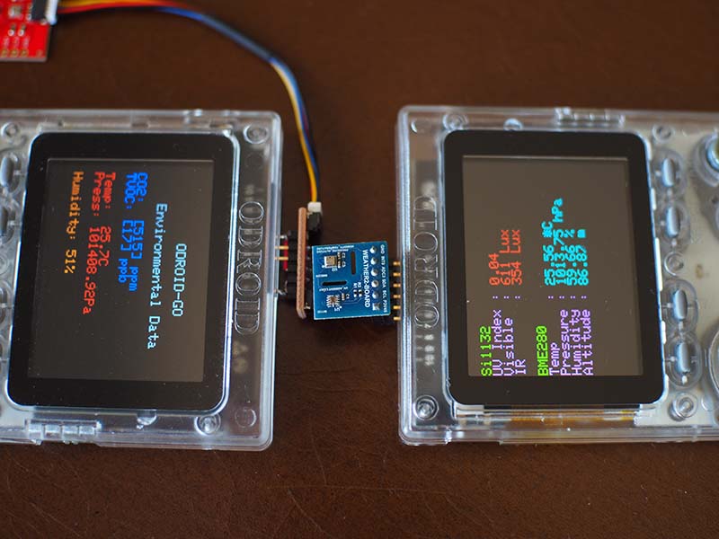
1. Plug the Qwiic Adapter into your ODROID-GO GPIO connector.

2. Connect the Qwiic cable to the Qwiic adapter and plug the other end into the Environmental Combo Breakout Board.

3. Input and upload this simple Arduino sketch to your ODROID-GO handheld gaming device:

/******************************************************************************
BME280Compensated.ino
Marshall Taylor @ SparkFun Electronics
April 4, 2017
https://github.com/sparkfun/CCS811_Air_Quality_Breakout
https://github.com/sparkfun/SparkFun_CCS811_Arduino_Library
This example uses a BME280 to gather environmental data that is then used
to compensate the CCS811.
Hardware Connections (Breakoutboard to Arduino):
3.3V to 3.3V pin
GND to GND pin
SDA to A4
SCL to A5
Resources:
Uses Wire.h for i2c operation
Hardware Connections:
Attach the Qwiic Environmental Combo to the Qwiic Adapter board mounted on your ODROID-GO
Display on the ODROID-GO @ 320x240
Development environment specifics:
Arduino IDE 1.8.1
This code is released under the [MIT License](http://opensource.org/licenses/MIT).
Please review the LICENSE.md file included with this example. If you have any questions
or concerns with licensing, please contact techsupport@sparkfun.com.
Distributed as-is; no warranty is given.
******************************************************************************/
#include 
#include 
#include 
#include

#define CCS811_ADDR 0x5B //Default I2C Address
//#define CCS811_ADDR 0x5A //Alternate I2C Address

//Global sensor objects
CCS811 myCCS811(CCS811_ADDR);
BME280 myBME280;

ILI9341 lcd = ILI9341();

void setup()
{
Serial.begin(9600);
Serial.println();
Serial.println("Apply BME280 data to CCS811 for compensation.");

Wire.begin();

//This begins the CCS811 sensor and prints error status of .begin()
CCS811Core::status returnCode = myCCS811.begin();
if (returnCode != CCS811Core::SENSOR_SUCCESS)

Serial.println("Problem with CCS811");
printDriverError(returnCode);

else

Serial.println("CCS811 online");

//Initialize BME280
//For I2C, enable the following and disable the SPI section
myBME280.settings.commInterface = I2C_MODE;
myBME280.settings.I2CAddress = 0x77;
myBME280.settings.runMode = 3; //Normal mode
myBME280.settings.tStandby = 0;
myBME280.settings.filter = 4;
myBME280.settings.tempOverSample = 5;
myBME280.settings.pressOverSample = 5;
myBME280.settings.humidOverSample = 5;

//Calling .begin() causes the settings to be loaded
delay(10); //Make sure sensor had enough time to turn on. BME280 requires 2ms to start up.
byte id = myBME280.begin(); //Returns ID of 0x60 if successful
if (id != 0x60)

Serial.println("Problem with BME280");

else

Serial.println("BME280 online");

// Setup LCD
lcd.begin();
lcd.setRotation(1);
lcd.fillScreen(BLACK);
lcd.setBrightness(255);
lcd.setTextFont(1);
lcd.setTextSize(2);
lcd.setCharCursor(10, 2);
lcd.setTextColor(LIGHTGREY);
lcd.println("ODROID-GO");
lcd.setCharCursor(5, 4);
lcd.println("Environmental Data");
lcd.setTextSize(2);

}
//---------------------------------------------------------------
void loop()
{
// Initiate the text cursor position
lcd.setCharCursor(1, 6);

//Check to see if data is available
if (myCCS811.dataAvailable())

//Calling this function updates the global tVOC and eCO2 variables
myCCS811.readAlgorithmResults();
//printData fetches the values of tVOC and eCO2
printData();

float BMEtempC = myBME280.readTempC();
float BMEhumid = myBME280.readFloatHumidity();

Serial.print("Applying new values (deg C, %): ");
Serial.print(BMEtempC);
Serial.print(",");
Serial.println(BMEhumid);
Serial.println();

//This sends the temperature data to the CCS811
myCCS811.setEnvironmentalData(BMEhumid, BMEtempC);

else if (myCCS811.checkForStatusError())

Serial.println(myCCS811.getErrorRegister()); //Prints whatever CSS811 error flags are detected

delay(2000); //Wait for next reading
}

//---------------------------------------------------------------
void printData()
{
lcd.setTextColor(BLUE, BLACK);
Serial.print(" CO2[");
lcd.print ("CO2: [");
Serial.print(myCCS811.getCO2());
lcd.print (myCCS811.getCO2());
Serial.print("]ppm");
lcd.println ("] ppm");

Serial.print(" TVOC[");
lcd.print (" TVOC: [");
Serial.print(myCCS811.getTVOC());
lcd.print (myCCS811.getTVOC());
Serial.print("]ppb");
lcd.println ("] ppb");
lcd.println (" ");

lcd.setTextColor(RED, BLACK);
Serial.print(" temp[");
lcd.print (" Temp: ");
Serial.print(myBME280.readTempC(), 1);
lcd.print (myBME280.readTempC(), 1);
Serial.print("]C");
lcd.println ("C");

Serial.print(" pressure[");
lcd.print (" Press: ");
Serial.print(myBME280.readFloatPressure(), 2);
lcd.print (myBME280.readFloatPressure(), 2);
Serial.print("]Pa");
lcd.println ("Pa");
lcd.println (" ");

lcd.setTextColor(ORANGE, BLACK);
Serial.print(" humidity[");
lcd.print (" Humidity: ");
Serial.print(myBME280.readFloatHumidity(), 0);
lcd.print (myBME280.readFloatHumidity(), 0);
Serial.print("]%");
lcd.println ("%");

Serial.println();
}

//printDriverError decodes the CCS811Core::status type and prints the
//type of error to the serial terminal.
//
//Save the return value of any function of type CCS811Core::status, then pass
//to this function to see what the output was.
void printDriverError( CCS811Core::status errorCode )
{
switch ( errorCode )

case CCS811Core::SENSOR_SUCCESS:
Serial.print("SUCCESS");
break;
case CCS811Core::SENSOR_ID_ERROR:
Serial.print("ID_ERROR");
break;
case CCS811Core::SENSOR_I2C_ERROR:
Serial.print("I2C_ERROR");
break;
case CCS811Core::SENSOR_INTERNAL_ERROR:
Serial.print("INTERNAL_ERROR");
break;
case CCS811Core::SENSOR_GENERIC_ERROR:
Serial.print("GENERIC_ERROR");
break;
default:
Serial.print("Unspecified error.");

}
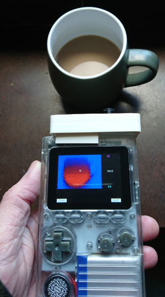
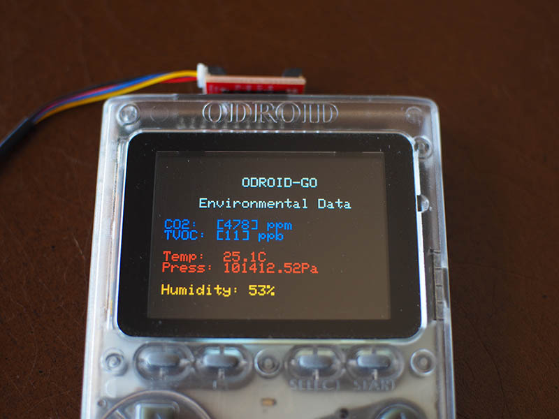
4. Use your newly built air quality sensor to discover who’s been using the formaldehyde without your permission.

Figure 4 - Compare the results between two similar environmental sensor boards. Does something smell fishy here?

NOTE: In order to obtain valid air quality output from the Environmental Combo board, you must do a single “burn-in”cycle of the CSS811 sensor for 48 hours AND you must perform a warm-up wait of 20 minutes before each use.

Do It Yourself 6-bay Network Access Storage (NAS): Leveraging the Power of the ODROID-H2

This article will instruct you on how to build a 6-Bay NAS server with ODROID-H2. A few weeks ago, a small project to build a 6-Bay NAS server was started with the ODROID-H2 (Rev.B) when it was released in June. Many users have asked if ODROID-H2 can run more than 2 drives using PCI-e to SATA expansion card and a couple of users have tried.

Case

I have tried to look for a decent case that has enough space in order to fit 6x 3.5" disk drives and the ODROID-H2. There are many NAS or HTPC cases that can fit the mini-ATX board, but the challenge was their height is either too low or the volume is not enough to install six HDD drives. The fancy cases with 4-6 hot-swap bays were too expensive or they only supported 2.5" drives. For enough installation space and a decent budget, the NAS case from https://bit.ly/2X82Qtr was chosen.

It has 3 brackets that can hold 2 x 3.5" drives each, and a standard ATX power can be located under the drive bays. It also has 4 PCB mounts on the bottom but their dimensions are for a standard ATX form factor in which ODROID-H2 will not fit, so a mount adaptor for ODROID-H2 is required.

Figure 1

Figure 2

Figure 3

Board mounting

Many of you have already noticed that the form factor of OROID-H2 is not compatible with any ATX specifications, and this causes some difficulty in mounting it in a standard PC case or HTPC case. The case that we purchased is also designed for a mini ATX board which is still big for ODROID-H2; therefore, a mounting adaptor board is necessary. In the beginning, an acrylic panel was considered as a material for the mounting adaptor board. However, it is too weak and I have to order a new razor cutting whenever I change the design. Eventually, I decided to build it with a 3D printer.

Figure 4

The panel has been attached to ODROD-H2 using the 10mm height PCB support. The height of 10mm is just enough in order to put ODROID-H2 on the top surface; otherwise, the memory socket will interfere with the mount. Since the height of the printed mounting panel is 3mm, ODROID-H2 is mounted at 13mm higher than other ATX boards and this causes an issue with the back panel.

Figure 5

Figure 6

As we have planned to run 6 drives with ODROID-H2, the SATA expansion card supports 4 additional SATA connectors for the M.2 slot which are apart from the 2 SATA slots from ODROID-H2. Attaching the SATA cables to the adaptor requires more space underneath the ODROID-H2, the right-angle type cable helps to save this space. However, using the cable still requires approximately 25mm from the bottom surface of ODROID-H2. Since we already have 13mm from the mounting panel, we had to gain the remaining 12mm from the case. Fortunately, the height of PCB mount holes is 12mm, which matches our requirements and the ODROID-H2 can be safely placed in the case.

Figure 7

Figure 8

Figure 9

Next, I had to address the problem with the back panel. Everything is higher than a regular PC board, since we mounted the ODROID-H2 using the standard ATX mount holes and made space for SATA cables on the underside. This means NAS users will have to give up using an audio connector. The Ethernet connectors, on the other hand, might be an issue. After attaching the back panel cover printed with the mounting panel, it is not quite aligned to the connectors of ODROID-H2 but is acceptable for our use.

Figure 10

Figure 11

I have another picture of attaching the Ethernet cables to ODROID-H2 while it is mounted in the case. It just barely fits for plugging in the cable to ODROID-H2 without any interference from the case. So I believe that attaching the Ethernet cable to ODROID-H2 is not a big problem at all, however, it is not not detachable once it has been attached.

Figure 12

We are planning to keep moving forward even though we have discovered the problems of the back panel and the tight Ethernet cable. Our NAS will run 24/7, therefore, the network cable will be fixed or the cable connection can be mounted on the other side of the case.

Power supply

We have purchased a 350W standard ATX power supply which fits perfectly inside the case. While 350W might seem like a higher wattage for running 6 HDD and the ODROID-H2, the price of such ATX power is not very high, so this power supply is acceptable. Other than the power supply rating, what we had to consider was if the PSU has enough SATA connectors. Since most PSUs under 500W has up to 4 SATA power connectors, one extra SATA extension cable had to be added for the remaining 2 HDD drives.

Figure 13

Supplying power to ODROID-H2 and 6 HDD is a challenge, but, more importantly, was the question of whether or not the system could be controlled via a single switch. This is because the standard ATX power is not only turned “on” when the power signal on the ATX power connector is triggered. Instead, we will need to monitor another signal which indicates whether the power state is good or not. Eventually it was decided to use the signal Power “on” with an ordinary switch module. This was the simplest way to control the PSU with the switch on it. A small switch has been purchased and it fits well in the extension card slot. The card slot bracket has to be cut as much as the length of the switch.

Figure 14

The wire color of Power-on signal on the PSU is green. This signal must be shorted to the ground in order to turn on the PSU. Since we have decided to use a toggle switch the green wire and a black wire have to be soldered to the switch.

Figure 15

Figure 16

The ODROID-H2 does not have standard PC-type pinouts for LED indicators or buttons. Therefore, in order to light the power LED, the wire should be connected to the voltage out on the expansion pinout. The DC 3.3V and the ground pins can be connected as shown below.

Figure 17

Figure 18

HDD installation and wiring

For this project, 6x Western Digital 1TB HDD were purchased and mounted to the bracket in the case.

Figure 19

The case comes with 3 brackets by default. Two HDDs can be mounted on each bracket.

Figure 20

Figure 21

Four HDDs with white cables will be connected through the M.2 SATA expansion board and the other two with red cables will be routed via onboard SATA connections. The power cables for the HDD drives will be connected using the SATA connectors on the PSU. However, we still need another "Y" cable which converts the single IDE connector to two SATA cables.

Figure 22

Figure 23

Setup BIOS

With its default setup, SATA adapter on M.2 slot will not work. To use properly, we have to configure BIOS settings. Enter BIOS by pressing the Delete key just after the power button is pushed. Then, you should see the screen shown in Figure 24.

Figure 24

You have to set 2 options:

  • Chipset - South Cluster Configuration - Miscellaneous Configuration - State After G3 to “S0 State” to make it turn on automatically when the power plugged.
  • Chipset - South Cluster Configuration - PCI Express Configuration - PCI Express Clock Gating to “Disabled” to make the M.2 to SATA adapter work properly.

Move using the arrow keys on the keyboard to them and set each option.

Figure 25

Figure 26

Installing Ubuntu

To its host operating system, we've decided to install Ubuntu 19.04. Download the latest OS image from Ubuntu download page (https://ubuntu.com/download), and flash that image into a USB stick using Etcher. Etcher is a multi-platform flashing tool. Plug the USB memory stick to H2 and power on. Then press F7 to enter choosing boot media screen. If the screen shows up, select the inserted USB boot media.

Figure 27

Continue installing Ubuntu per your preferences. Just be aware of selecting a hard drive when you select a root media during installation. Keeping the system up-to-date is highly recommended in any case of application use, in most cases.

To check whether the hard drives were installed properly, you can look into the output of dmesg:

$ dmesg | grep scsi
[    2.067831] scsi host0: ahci
[    2.068684] scsi host1: ahci
[    2.080796] scsi host2: ahci
[    2.080964] scsi host3: ahci
[    2.084816] scsi host4: ahci
[    2.084976] scsi host5: ahci
[    2.548364] scsi 0:0:0:0: Direct-Access     ATA      WDC WD10EFRX-68F 0A82 PQ: 0 ANSI: 5
[    2.549029] sd 0:0:0:0: Attached scsi generic sg0 type 0
[    2.549321] scsi 1:0:0:0: Direct-Access     ATA      WDC WD10EFRX-68F 0A82 PQ: 0 ANSI: 5
[    2.549627] sd 1:0:0:0: Attached scsi generic sg1 type 0
[    2.563013] scsi 2:0:0:0: Direct-Access     ATA      WDC WD10EFRX-68F 0A82 PQ: 0 ANSI: 5
[    2.563292] sd 2:0:0:0: Attached scsi generic sg2 type 0
[    2.563497] scsi 3:0:0:0: Direct-Access     ATA      WDC WD10EFRX-68F 0A82 PQ: 0 ANSI: 5
[    2.563693] sd 3:0:0:0: Attached scsi generic sg3 type 0
[    2.563875] scsi 4:0:0:0: Direct-Access     ATA      WDC WD10EFRX-68F 0A82 PQ: 0 ANSI: 5
[    2.564070] sd 4:0:0:0: Attached scsi generic sg4 type 0
[    2.564268] scsi 5:0:0:0: Direct-Access     ATA      WDC WD10EFRX-68F 0A82 PQ: 0 ANSI: 5
[    2.564444] sd 5:0:0:0: Attached scsi generic sg5 type 0
This shows that those 6 drives are recognized normally. If yours aren’t, you should check the hardware connection or BIOS settings.

Partition Hard Drives

Check the installed hard drives using the following commands.

$ sudo fdisk -l | grep sd
Disk /dev/sda: 931.5 GiB, 1000204886016 bytes, 1953525168 sectors
Disk /dev/sdb: 931.5 GiB, 1000204886016 bytes, 1953525168 sectors
Disk /dev/sdc: 931.5 GiB, 1000204886016 bytes, 1953525168 sectors
Disk /dev/sdd: 931.5 GiB, 1000204886016 bytes, 1953525168 sectors
Disk /dev/sde: 931.5 GiB, 1000204886016 bytes, 1953525168 sectors
Disk /dev/sdf: 931.5 GiB, 1000204886016 bytes, 1953525168 sectors
Next, create a partition using the parted tool. You can use fdisk to partition them but GPT partition table should be created in order to use more than 2TB hard drive. Partition the disks respectively referring to the following procedures:
$ sudo parted /dev/sda
GNU Parted 3.2
Using /dev/sda
Welcome to GNU Parted! Type 'help' to view a list of commands.
(parted) mklabel gpt                                                      
(parted) print free                                                       
Model: ATA WDC WD10EFRX-68F (scsi)
Disk /dev/sda: 1000GB
Sector size (logical/physical): 512B/4096B
Partition Table: gpt
Disk Flags: 
 
Number  Start   End     Size    File system  Name  Flags
        17.4kB  1000GB  1000GB  Free Space
 
(parted) mkpart primary 1M 1000GB                                         
(parted) p                                                                
Model: ATA WDC WD10EFRX-68F (scsi)
Disk /dev/sda: 1000GB
Sector size (logical/physical): 512B/4096B
Partition Table: gpt
Disk Flags: 
 
Number  Start   End     Size    File system  Name     Flags
 1      1049kB  1000GB  1000GB               primary
 
(parted) q                                                                
Information: You may need to update /etc/fstab.
Check the changes applied.
$ lsblk | grep sd
sda            8:0    0 931.5G  0 disk 
└─sda1         8:1    0 931.5G  0 part 
sdb            8:16   0 931.5G  0 disk 
└─sdb1         8:17   0 931.5G  0 part 
sdc            8:32   1 931.5G  0 disk 
└─sdc1         8:33   1 931.5G  0 part 
sdd            8:48   1 931.5G  0 disk 
└─sdd1         8:49   1 931.5G  0 part 
sde            8:64   1 931.5G  0 disk 
└─sde1         8:65   1 931.5G  0 part 
sdf            8:80   1 931.5G  0 disk 
└─sdf1         8:81   1 931.5G  0 part
We can see each all hard drive has one partition. After partitioning all of the drives, now it's time to set RAID 6 up on our NAS.

Configure RAID 6

Here are two main reasons for using RAID level 6:

  • It is more robust than RAID 5, because it uses one more disk for parity.
  • There will be no data loss even after 2 disk fails. We can rebuild it after replacing the failed disk.

However, it also has some overhead: double parity can verify its stability, but it also comes with poor writing performance. A minimum of 4 disks are required to build with RAID 6. Since we have 6 hard drives which have 1TB capacity each, we can build using RAID 6 and there will be 4TB capacity that we can use.

To setup RAID without a physical RAID controller on Linux system, we have to use mdadm tool. It is provided by package manager on each Linux distros:

$ sudo apt install mdadm
We already know that those 6 drives are allocated as /dev/sda to /dev/sdf. Create an array using the following command:
$ sudo mdadm --create /dev/md0 --level=6 --raid-devices=6 /dev/sda1 /dev/sdb1 /dev/sdc1 /dev/sdd1 /dev/sde1 /dev/sdf1
mdadm: Defaulting to version 1.2 metadata
mdadm: array /dev/md0 started.
The /dev/md0 device file will be created. You should use that device like a single hard drive partition, so if you want to mount that array to a directory, you can just mount with that device file. Format that partition and mount to the /media/storage:
$ sudo mkfs.ext4 /dev/md0
mke2fs 1.44.6 (5-Mar-2019)
Creating filesystem with 976628736 4k blocks and 244162560 inodes
Filesystem UUID: 100a470d-96f1-47d2-8cf0-a211c010e8b9
Superblock backups stored on blocks: 
  32768, 98304, 163840, 229376, 294912, 819200, 884736, 1605632, 2654208, 
  4096000, 7962624, 11239424, 20480000, 23887872, 71663616, 78675968, 
  102400000, 214990848, 512000000, 550731776, 644972544
 
Allocating group tables: done                            
Writing inode tables: done                            
Creating journal (262144 blocks): done
Writing superblocks and filesystem accounting information: done       
 
$ sudo mkdir /media/storage
$ sudo mount /dev/md0 /media/storage/
Check if it mounted properly.
$ cat /proc/mounts | grep md0
/dev/md0 /media/storage ext4 rw,relatime,stripe=512 0 0
You also can see the RAID configurations:
$ sudo mdadm --detail /dev/md0
/dev/md0:
           Version : 1.2
     Creation Time : Mon Jun 17 18:08:26 2019
        Raid Level : raid6
        Array Size : 3906514944 (3725.54 GiB 4000.27 GB)
     Used Dev Size : 976628736 (931.39 GiB 1000.07 GB)
      Raid Devices : 6
     Total Devices : 6
       Persistence : Superblock is persistent
 
     Intent Bitmap : Internal
 
       Update Time : Mon Jun 17 18:27:08 2019
             State : active, resyncing 
    Active Devices : 6
   Working Devices : 6
    Failed Devices : 0
     Spare Devices : 0
 
            Layout : left-symmetric
        Chunk Size : 512K
 
Consistency Policy : bitmap
 
     Resync Status : 8% complete
 
              Name : ODROID-H2:0  (local to host ODROID-H2)
              UUID : d4759dbb:65fd2b07:d5f4f9c3:0fba55cc
            Events : 253
 
    Number   Major   Minor   RaidDevice State
       0       8        1        0      active sync   /dev/sda1
       1       8       17        1      active sync   /dev/sdb1
       2       8       33        2      active sync   /dev/sdc1
       3       8       49        3      active sync   /dev/sdd1
       4       8       65        4      active sync   /dev/sde1
       5       8       81        5      active sync   /dev/sdf1
Since this RAID array was just created, a resync process to synchronize with the other devices needs to be performed. You can see the status of the resync process with the following command:
$ cat /proc/mdstat 
Personalities : [linear] [multipath] [raid0] [raid1] [raid6] [raid5] [raid4] [raid10] 
md0 : active raid6 sdf1[5] sde1[4] sdd1[3] sdc1[2] sdb1[1] sda1[0]
      3906514944 blocks super 1.2 level 6, 512k chunk, algorithm 2 [6/6] [UUUUUU]
      [=>...................]  resync =  9.6% (93909272/976628736) finish=120.2min speed=122360K/sec
      bitmap: 8/8 pages [32KB], 65536KB chunk
 
unused devices:
Once the rsync process completes, you can see a message via dmesg:
$ dmesg | grep resync
[  199.311304] md: resync of RAID array md0
[10093.988694] md: md0: resync done.
You also would set your system environment by adding an entry to /etc/fstab and configuring the SAMBA or SFTP server to share your data by using that RAID-ed hard drives. There are many management guides for further use of RAID built system including adding spare drives or dealing with failed devices, but this guide will not go into those details.

Benchmarks

I ran iozone3 to evaluate its performance of the H2 with RAID level 6 on 6 hard drives, after making sure that the resync process had completed:

$ sudo iozone -e -I -a -s 100M -r 4k -r 16384k -i 0 -i 1 -i 2
  Iozone: Performance Test of File I/O
          Version $Revision: 3.429 $
    Compiled for 64 bit mode.
    Build: linux-AMD64 
 
  Contributors:William Norcott, Don Capps, Isom Crawford, Kirby Collins
               Al Slater, Scott Rhine, Mike Wisner, Ken Goss
               Steve Landherr, Brad Smith, Mark Kelly, Dr. Alain CYR,
               Randy Dunlap, Mark Montague, Dan Million, Gavin Brebner,
               Jean-Marc Zucconi, Jeff Blomberg, Benny Halevy, Dave Boone,
               Erik Habbinga, Kris Strecker, Walter Wong, Joshua Root,
               Fabrice Bacchella, Zhenghua Xue, Qin Li, Darren Sawyer,
               Vangel Bojaxhi, Ben England, Vikentsi Lapa.
 
  Run began: Tue Jun 18 10:03:49 2019
 
  Include fsync in write timing
  O_DIRECT feature enabled
  Auto Mode
  File size set to 102400 kB
  Record Size 4 kB
  Record Size 16384 kB
  Command line used: iozone -e -I -a -s 100M -r 4k -r 16384k -i 0 -i 1 -i 2
  Output is in kBytes/sec
  Time Resolution = 0.000001 seconds.
  Processor cache size set to 1024 kBytes.
  Processor cache line size set to 32 bytes.
  File stride size set to 17 * record size.
                                                              random    random     bkwd    record    stride                                    
              kB  reclen    write  rewrite    read    reread    read     write     read   rewrite      read   fwrite frewrite    fread  freread
          102400       4     9241    14364    27027    29648    15326     4404                                                          
          102400   16384   208414   209245   521260   669540   731096   177565                                                          
 
iozone test complete.
Since the 6 hard drives are linked to each other, its performance is far better than from the results with the only 1 hard drive.

Figure 28 - Benchmarks

RAID 6 uses double parity, but 6 hard drives perform like a kind of multiprocessing in CPU literally, so the overall speed can be greatly increased. If using RAID level 5, the performance would be a little bit better than this since RAID 5 uses single parity. Therefore, there's no reason not to use RAID 6 when you have more than 4 hard drives, especially, since the H2 is a powerful host hardware for NAS use at a reasonable price, with 2 Gigabit LAN ports as an added bonus for connectivity. We will address Software Installation in an upcoming article.

References

https://forum.odroid.com/viewtopic.php?f=172&t=35309https://www.tecmint.com/create-raid-6-in-linux/ https://askubuntu.com/questions/350266/how-can-i-create-a-raid-array-with-2tb-disks

The G Spot: Your Go-to Destination for all Things Android Gaming

The upcoming summer months could be very exciting for Android gamers. Google Stadia, E3, and some long-awaited, big-name game releases have all been penciled into my calendar. One of these major game releases is Elder Scrolls: Blades. I’ve been singing the praises of this title for the last couple of months, so I felt that it was high time to do a quick play-test of the early access version.

Figure 1 - You will need a constant Internet connection for playing the early access version

Right out of the chute, this early access version of the game requires that you have an Internet connection. Even though the game is a fairly reasonable 120Mb download, the initial startup of the game will require another 880Mb download along with an additional 380Mb update! Furthermore, each time you start a gaming session, there is a lengthy delay while the version numbers of the updates are verified with the Bethesda servers.

Does all of this online access make Elder Scrolls: Blades a worthwhile gaming experience? That answer is a mixed bag. Granted, many of the visual effects are stunningly rendered and richly animated, but the actual game play leaves a lot to be desired.

Relying on a point-touch-move interactive exploration/navigation format, the similar combat actions in Elder Scrolls: Blades featuring a point-touch-stab attack mode seem amateurish and poorly developed. Coupled with the basic, wooden dialog voiced by various antagonists you encounter throughout the game, this early access version seem like a half-baked effort that isn’t even close to being ready for prime time.

Figure 2 - Not much of a threat here—eight pokes from my finger/sword will quickly dispatch ye

Ailment

In this free action title from BeardyBird Games, you are an astronaut who wakes up on a spaceship full of problems and inhabited by enemies. There is a whole rash of questions that you must answer. Why are they trying to kill you? Who are they? And, most importantly, where are you? Ailment is part puzzle-solving game and part epic shoot ‘em up combat game. The result is a game that includes hidden references to classic science fiction alongside the final goal of figuring out what happened on this spaceship.

https://www.youtube.com/watch?v=T2inRVXYRNU
Figure 3 - You’ll be talking to yourself a LOT in Ailment. Image courtesy of BeardyBird Games.

Despotism 3K

Featuring a unique take on the Sim IV game concept, this release from Konfa Games is much more mature and much more fun(ny). Reduced to a new $3.49 purchase price, Despotism 3K offers an Artificial Intelligence (AI) master being who controls a throng of subservient humans to do its bidding. And many of these chores can be fatal. But pity not the humans or you’ll lose this game.

https://www.youtube.com/watch?v=OT3QJZ_mrJo

Cool Android Game Summer Picks

Asphalt 9: Legends – FREE Crashlands – $4.99 Riptide GTP Series – $2.99 Shadowgun Legends – FREE Elder Scrolls: Blades – FREE. PLEASE try before you buy this one.

Kodi and Advanced Mame on ODROID-XU4 - Part 2

This is a continuation of a guide for setting up Kodi with Mame, which details how to install the joystick. Ideally, playing with MAME requires a nice joystick. Here are two examples of joystick I've built myself. It's a good exercise of woodwork, painting, designing and electronics and a fun game for the family. I've made them with planks I collected from a construction site nearby. Good for the environment to recycle things too.

Figure 1 - Custom made Joystick for Kodi with Mame

Figure 2 - Custom made Joystick for Kodi with Mame

1. Install the software to support and calibrate the joystick. Arcade joysticks are easy to build or can be bought on Internet. They work very well and ideal for playing with MAME's arcade games.

$ sudo apt install joystick jstest-gtk

Calibrate the joystick

Since most Mame games will require a simple joystick with buttons, calibration will be very simple. You can use jstest-gtk, but because we already installed Kodi, we will do the calibration from the command line only.

With a click joystick, the only calibration is to associate buttons (inside the joystick for the directions and fire/select buttons), with their respective direction or function. The calibration will be available system-wide and therefore will be used by mame.

If you can plug your joystick into your Linux machine, I recommend to use a small program called jstest-gtk. It's a simple GUI, and you can check the proper direction of your joystick. In my case, I use a DragonRise compatible joystick (the one on the picture), with 4 connectors for up, down, left and right. But there are a few problems which we will fix with the calibration. First of all, the left-right and up-down are inversed and then the up-down axis is upside down. So to make it short: up is right, down is left, right is down and left is up!!! I can see that on the jstest-gtk interface.

Another option (since Kodi 17) is to setup your joystick directly from Kodi. A tutorial is available at https://kodi.wiki/view/HOW-TO:Configure_controllers. As there are many models of joystick, I won't cover all the possible configurations, but please contribute and I'll add your solution to this guide.

If you want to play with the joystick configuration and assign various command to each button or change the directions, you need to provide a configuration file. Let's call it myjoyremap.cfg. In my case, I use the following file, but yours might differ a lot depending on what you want to achieve and your joystick's model:

< ?xml version="1.0"? >
< mameconfig version="10" >
< system name="default" >
< input >
< port type="P1_JOYSTICK_UP" > < newseq type="standard" > JOYCODE_1_XAXIS_RIGHT_SWITCH < /newseq > < /port >
< port type="P1_JOYSTICK_DOWN" > < newseq type="standard" > JOYCODE_1_XAXIS_LEFT_SWITCH < /newseq > < /port >
< port type="P1_JOYSTICK_LEFT" > < newseq type="standard" > JOYCODE_1_YAXIS_UP_SWITCH < /newseq > < /port >
< port type="P1_JOYSTICK_RIGHT" > < newseq type="standard" > JOYCODE_1_YAXIS_DOWN_SWITCH < /newseq > < /port >

< port type="P1_BUTTON1" > < newseq type="standard" > JOYCODE_1_BUTTON1 < /newseq > < /port >
< port type="P1_BUTTON2" > < newseq type="standard" > JOYCODE_1_BUTTON3 < /newseq > < /port >
< port type="P1_BUTTON3" > < newseq type="standard" > JOYCODE_1_BUTTON5 < /newseq > < /port >
< port type="P1_BUTTON4" > < newseq type="standard" > JOYCODE_1_BUTTON7 < /newseq > < /port >

< port type="P1_BUTTON5" > < newseq type="standard" > JOYCODE_1_BUTTON2 < /newseq > < /port >
< port type="P1_BUTTON6" > < newseq type="standard" > JOYCODE_1_BUTTON4 < /newseq > < /port >
< port type="P1_BUTTON7" > < newseq type="standard" > JOYCODE_1_BUTTON6 < /newseq > < /port >

< port type="P1_BUTTON8" > < newseq type="standard" > NONE < /newseq > < /port >
< port type="P1_BUTTON9" > < newseq type="standard" > NONE < /newseq > < /port >
< port type="P1_BUTTON10" > < newseq type="standard" > NONE < /newseq > < /port >
< port type="P1_BUTTON11" > < newseq type="standard" > NONE < /newseq > < /port >
< port type="P1_BUTTON12" > < newseq type="standard" > NONE < /newseq > < /port >

< port type="P1_START" > < newseq type="standard" > JOYCODE_1_BUTTON9 < /newseq > < /port >
< port type="P1_SELECT" > < newseq type="standard" > JOYCODE_1_BUTTON10 < /newseq > < /port >
< port type="COIN1" > < newseq type="standard" > JOYCODE_1_BUTTON8 < /newseq > < /port >
< port type="START1" > < newseq type="standard" > KEYCODE_1 OR JOYCODE_1_BUTTON9 < /newseq > < /port >

< port type="P1_PEDAL" > < newseq type="standard" > NONE < /newseq > < newseq type="increment" > NONE < /newseq >
< /port > < port type="P1_PEDAL2" > < newseq type="standard" > NONE < /newseq > < newseq type="increment" > NONE < /newseq > < /port >
< port type="P1_PEDAL3" > < newseq type="increment" > NONE < /newseq > < /port >
< port type="P1_PADDLE" > < newseq type="standard" > NONE < /newseq > < newseq type="increment" > NONE < /newseq > < newseq type="decrement" > NONE < /newseq > < /port >
< port type="P1_PADDLE_V" > < newseq type="standard" > NONE < /newseq > < newseq type="increment" > NONE < /newseq > < newseq type="decrement" > NONE < /newseq > < /port >
< port type="P1_POSITIONAL" > < newseq type="standard" > NONE < /newseq > < newseq type="increment" > NONE < /newseq > < newseq type="decrement" > NONE < /newseq > < /port >
< port type="P1_POSITIONAL_V" > < newseq type="standard" > NONE < /newseq > < newseq type="increment" > NONE < /newseq > < newseq type="decrement" > NONE < /newseq > < /port >
< port type="P1_DIAL" > < newseq type="standard" > NONE < /newseq > < newseq type="increment" > NONE < /newseq > < newseq type="decrement" > NONE < /newseq > < /port >
< port type="P1_DIAL_V" > < newseq type="standard" > NONE < /newseq > < newseq type="increment" > NONE < /newseq > < newseq type="decrement" > NONE < /newseq > < /port >
< port type="P1_TRACKBALL_X" > < newseq type="standard" > NONE < /newseq > < newseq type="increment" > NONE < /newseq > < newseq type="decrement" > NONE < /newseq > < /port >
< port type="P1_TRACKBALL_Y" > < newseq type="standard" > NONE < /newseq > < newseq type="increment" > NONE < /newseq > < newseq type="decrement" > NONE < /newseq > < /port >
< port type="P1_AD_STICK_X" > < newseq type="standard" > NONE < /newseq > < newseq type="increment" > NONE < /newseq > < newseq type="decrement" > NONE < /newseq > < /port >
< port type="P1_AD_STICK_Y" > < newseq type="standard" > NONE < /newseq > < newseq type="increment" > NONE < /newseq > < newseq type="decrement" > NONE < /newseq > < /port >
< port type="P1_AD_STICK_Z" > < newseq type="standard" > NONE < /newseq > < newseq type="increment" > NONE < /newseq > < newseq type="decrement" > NONE < /newseq > < /port >
< port type="P1_LIGHTGUN_X" > < newseq type="standard" > NONE < /newseq > < newseq type="increment" > NONE < /newseq > < newseq type="decrement" > NONE < /newseq > < /port >
< port type="P1_LIGHTGUN_Y" > < newseq type="standard" > NONE < /newseq > < newseq type="increment" > NONE < /newseq > < newseq type="decrement" > NONE < /newseq > < /port >

< port type="P2_JOYSTICK_UP" > < newseq type="standard" > JOYCODE_2_XAXIS_RIGHT_SWITCH < /newseq > < /port >
< port type="P2_JOYSTICK_DOWN" > < newseq type="standard" > JOYCODE_2_XAXIS_LEFT_SWITCH < /newseq > < /port >
< port type="P2_JOYSTICK_LEFT" > < newseq type="standard" > JOYCODE_2_YAXIS_UP_SWITCH < /newseq > < /port >
< port type="P2_JOYSTICK_RIGHT" > < newseq type="standard" > JOYCODE_2_YAXIS_DOWN_SWITCH < /newseq > < /port >

< port type="P2_BUTTON1" > < newseq type="standard" > JOYCODE_2_BUTTON1 < /newseq > < /port >
< port type="P2_BUTTON2" > < newseq type="standard" > JOYCODE_2_BUTTON3 < /newseq > < /port >
< port type="P2_BUTTON3" > < newseq type="standard" > JOYCODE_2_BUTTON5 < /newseq > < /port >
< port type="P2_BUTTON4" > < newseq type="standard" > JOYCODE_2_BUTTON7 < /newseq > < /port >

< port type="P2_BUTTON5" > < newseq type="standard" > JOYCODE_2_BUTTON2 < /newseq > < /port >
< port type="P2_BUTTON6" > < newseq type="standard" > JOYCODE_2_BUTTON4 < /newseq > < /port >
< port type="P2_BUTTON7" > < newseq type="standard" > JOYCODE_2_BUTTON6 < /newseq > < /port >

< port type="P2_BUTTON8" > < newseq type="standard" > NONE < /newseq > < /port >
< port type="P2_BUTTON9" > < newseq type="standard" > NONE < /newseq > < /port >
< port type="P2_BUTTON10" > < newseq type="standard" > NONE < /newseq > < /port >
< port type="P2_BUTTON11" > < newseq type="standard" > NONE < /newseq > < /port >
< port type="P2_BUTTON12" > < newseq type="standard" > NONE < /newseq > < /port >

< port type="P2_START" > < newseq type="standard" > JOYCODE_2_BUTTON9 < /newseq > < /port >
< port type="P2_SELECT" > < newseq type="standard" > JOYCODE_2_BUTTON10 < /newseq > < /port >
< port type="COIN2" > < newseq type="standard" > JOYCODE_2_BUTTON8 < /newseq > < /port >
< port type="START2" > < newseq type="standard" > KEYCODE_2 OR JOYCODE_2_BUTTON9 < /newseq > < /port >

< port type="P2_PEDAL" > < newseq type="standard" > NONE < /newseq > < newseq type="increment" > NONE < /newseq >
< /port > < port type="P2_PEDAL2" > < newseq type="standard" > NONE < /newseq > < newseq type="increment" > NONE < /newseq > < /port >
< port type="P2_PEDAL3" > < newseq type="increment" > NONE < /newseq > < /port >
< port type="P2_PADDLE" > < newseq type="standard" > NONE < /newseq > < newseq type="increment" > NONE < /newseq > < newseq type="decrement" > NONE < /newseq > < /port >
< port type="P2_PADDLE_V" > < newseq type="standard" > NONE < /newseq > < newseq type="increment" > NONE < /newseq > < newseq type="decrement" > NONE < /newseq > < /port >
< port type="P2_POSITIONAL" > < newseq type="standard" > NONE < /newseq > < newseq type="increment" > NONE < /newseq > < newseq type="decrement" > NONE < /newseq > < /port >
< port type="P2_POSITIONAL_V" > < newseq type="standard" > NONE < /newseq > < newseq type="increment" > NONE < /newseq > < newseq type="decrement" > NONE < /newseq > < /port >
< port type="P2_DIAL" > < newseq type="standard" > NONE < /newseq > < newseq type="increment" > NONE < /newseq > < newseq type="decrement" > NONE < /newseq > < /port >
< port type="P2_DIAL_V" > < newseq type="standard" > NONE < /newseq > < newseq type="increment" > NONE < /newseq > < newseq type="decrement" > NONE < /newseq > < /port >
< port type="P2_TRACKBALL_X" > < newseq type="standard" > NONE < /newseq > < newseq type="increment" > NONE < /newseq > < newseq type="decrement" > NONE < /newseq > < /port >
< port type="P2_TRACKBALL_Y" > < newseq type="standard" > NONE < /newseq > < newseq type="increment" > NONE < /newseq > < newseq type="decrement" > NONE < /newseq > < /port >
< port type="P2_AD_STICK_X" > < newseq type="standard" > NONE < /newseq > < newseq type="increment" > NONE < /newseq > < newseq type="decrement" > NONE < /newseq > < /port >
< port type="P2_AD_STICK_Y" > < newseq type="standard" > NONE < /newseq > < newseq type="increment" > NONE < /newseq > < newseq type="decrement" > NONE < /newseq > < /port >
< port type="P2_AD_STICK_Z" > < newseq type="standard" > NONE < /newseq > < newseq type="increment" > NONE < /newseq > < newseq type="decrement" > NONE < /newseq > < /port >
< port type="P2_LIGHTGUN_X" > < newseq type="standard" > NONE < /newseq > < newseq type="increment" > NONE < /newseq > < newseq type="decrement" > NONE < /newseq > < /port >
< port type="P2_LIGHTGUN_Y" > < newseq type="standard" > NONE < /newseq > < newseq type="increment" > NONE < /newseq > < newseq type="decrement" > NONE < /newseq > < /port >

< /input >
< /system >
< /mameconfig >
After saving the file, copy it to /media/usb/AML-assets/ctrlr/. Then, you can edit this file to adjust it to your own joystick. My joystick (which I built myself, hence the problem mentioned above) has a 90 degrees misconfiguration. In the XML file, you have two parts: one for the Player 1 joystick and another part for the Player 2 joystick. Each line with type="P1_JOYSTICK_UP" is the direction as understood by Mame. Then, the real configuration comes after as JOYCODE_1_XAXIS_RIGHT_SWITCH. Therefore, this line means that when my joystick sends a code for RIGHT, mame will interpret it as UP. Below this, I configured the buttons 1 to 8 and the START and SELECT buttons. Then I do the same for the Player's 2 joystick.

Finally, you can add it to the mame.ini configuration file by using the following command:

$ echo "ctrlr myjoyremap" | sudo tee -a /etc/mame/mame.ini

Remove unused software

This section is not mandatory, but you can find it useful to make your ODROID-XU4 lighter and more responsive. The XU4 has 2GB of memory, which is currently considered good for a Single Board Computer. Most of them have 0.5 to 1GB, but I see some 2 to 4 GB finally coming onto the market. So memory is a precious resource as well as CPU cycles. You don't want any slowdown of your machine while watching a movie or playing a game.

I selected a few services which I think are not necessary for a Kodi/Mame installation. Here is the way to stop and disable them. However, we will not uninstall the software, so that you can enable them again, should your needs change in the future.

1. CUPS is a print server, and since you don't really need to print from Kodi or Mame, it's safe to remove the print server (named CUPS):

$ sudo systemctl stop cups
$ sudo systemctl stop cups-browsed
$ sudo systemctl disable cups
$ sudo systemctl disable cups-browsed
To re-enable it:
$ sudo systemctl enable cups
$ sudo systemctl start cups
2. UPower controls the power source, and is useful with a smartphone, laptop or embedded system. However, in the case of a Kodi/Mame entertainment system in your living room, the only power source is the socket wall and your ODROID-XU4 is supposed to be connected all the time. So you can safely remove this one too:
$ sudo systemctl stop upower
$ sudo systemctl disable upower
3. Whoopsie is the error reporting daemon for Ubuntu, mainly used by desktop environment when something crashes. As we're only using Kodi, it's not necessary here:
$ sudo systemctl stop whoopsie
$ sudo systemctl disable whoopsie
4. ModemManager is a daemon which controls mobile broadband (2G/3G/4G) devices and connections. The ODROID-XU4 is connected to an ethernet (or a wifi if you have one) and does not need a _modem_ connection.
$ sudo systemctl stop ModemManager
$ sudo systemctl disable ModemManager
5. unattended-upgrades is a daemon to automatically update the system. I like when a computer works for me but in this specific case, we will avoid doing any automatic update. The reason is we want a stable entertainment system for all the family, which is available at any time. We don't want to have to do maintenance, just before launching the family movie, because an update didn't work:
$ sudo systemctl stop unattended-upgrades
$ sudo systemctl disable unattended-upgrades
If you want to upgrade your ODROID-XU4, you can still do it manually by running first an update of the packages' database:
$ sudo apt update
$ sudo apt upgrade
Personally, I'm a big fan of a software called Synaptic, which is a GUI for apt-based systems like Ubutun and Debian. I recommend it:
$ sudo apt install synaptic

Set the clock

You can synchronize the clock to a time server on the net and always have your ODROID set to the most accurate time. Moreover, you want to set the clock to your timezone.

First, we install a Network Time Protocol (NTP) client which will connect to time server to get an accurate time:

$ sudo apt install chrony
Then, we search for the time zone. It will be something like Europe/Zurich or Pacific/Auckland. To find yours, use the following command:
$ timedatectl list-timezones
Search and note your own time zone. Let's say you live near the North Pole in Longyearbyen, you will find the time zone in the list given above as Arctic/Longyearbyen. Then, tune your ODROID-XU4:
$ sudo timedatectl set-timezone Arctic/Longyearbyen
For comments, questions, and suggestions, please visit the original ODROID Forum thread at, https://forum.odroid.com/viewtopic.php?f=52&t=34760, or the GitHub repository at https://github.com/yimyom/odroid-xu4-setup.

Zoneminder - Part 2: Building the Package From Source on the ODROID-XU4

ZoneMinder is an integrated set of applications that provide a complete surveillance solution allowing capture, analysis, recording, and monitoring of any CCTV or security cameras.

Main features

    • Monitor from anywhere--Zoneminder has a full-featured web-based interface; you can access ZoneMinder from any internet-accessible device.
    • Use any camera--ZoneMinder allows you to use any analog or IP-enabled camera.
    • Control your data--ZoneMinder is fully on-premises; it allows you to own your data and control where it goes.
    • Run small or super-big systems--suitable for home and small business use, as well as multi-server enterprise deployments. It is compatible with many platforms, including ARM technology (ODROID-XU4 is built on an ARM platform).
    • Keep track of what matters--ZoneMinder allows you to browse information intuitively. Drill down to what you want to see in a matter of seconds.
    • Actively maintained and free of charge--ZoneMinder is actively maintained by a team committed to open source

.

Recently, I moved the ZoneMinder application from my old Radxa Rock Pro (an ARM board) to the more powerful ODROID-XU4. There is a harder way--building the package from source--to obtain a working setup: ODROID-XU4 - Ubuntu 16.04.3 LTS – Zoneminder 1.30.4.

Figure 1 – ZoneMinder console, configured with seven cameras

Figure 2 – ZoneMinder, watching camera #2

Installation

Let’s install Zoneminder on our ODROID-XU4 board. First, install Ubuntu 16.04.3 LTS image (upstream Release 4.14.y) on your SD card. This distro is provided by Hardkernel at the address: https://wiki.odroid.com/odroid-xu4/os_images/linux/ubuntu_4.14/20171213 Then upgrade the system:

$ sudo apt update
$ sudo apt upgrade
$ sudo apt dist-upgrade
$ sudo apt install linux-image-xu3 
$ sudo apt autoremove
$ sudo reboot
Now install LAMP (i.e.: apache, mysql, php) on the board:
$ sudo apt install apache2
$ sudo apt install mysql-server
$ sudo apt install php libapache2-mod-php php-mysql
Now install Zoneminder 1.30.4 (**):
$ sudo -i
Tweak MySQL configuration (not needed for ZoneMinder 1.32 or greater):
$ rm /etc/mysql/my.cnf (this removes the current symbolic link)
$ cp /etc/mysql/mysql.conf.d/mysqld.cnf /etc/mysql/my.cnf

$ nano /etc/mysql/my.cnf
In the [mysqld] section add the following:
$ sql_mode = NO_ENGINE_SUBSTITUTION
Then restart MySQL:
$ systemctl restart mysql
Now build ZoneMinder 1.30.4: first add repository and download tools,
$ add-apt-repository ppa:iconnor/zoneminder-master
$ apt-get update
$ apt-get install php-apcu-bc
$ sudo apt-get install gdebi-core

$ sudo wget https://raw.githubusercontent.com/ZoneMinder/ZoneMinder/master/utils/do_debian_package.sh
$ sudo chmod a+x do_debian_package.sh
$ sudo apt-get install devscripts
$ sudo apt install git
then the real “very long” build process:
$ sudo ./do_debian_package.sh --snapshot=NOW --branch=1.30.4 --type=local
Now install ZoneMinder 1.30.4 (use the ls command to discover yyyymmddhhmmss to be used in zoneminder_1.30.4~yyyymmddhhmmss-xenial_armhf.deb):
$ sudo gdebi zoneminder_1.30.4~yyyymmddhhmmss-xenial_armhf.deb
Create ZoneMinder database:
$ mysql -uroot -p < /usr/share/zoneminder/db/ZoneMinder_create.sql
$ mysql -uroot -p -e "grant lock tables,alter,drop,select,insert,update,delete,create,index,alter routine,create routine, trigger,execute on zm.* to 'zmuser'@localhost identified by 'zmpass';"
Add permissions:
$ chmod 740 /etc/zm/zm.conf
$ chown root:www-data /etc/zm/zm.conf
$ chown -R www-data:www-data /usr/share/zoneminder/
Enable modules and ZoneMinder configuration:
$ a2enmod cgi
$ a2enmod rewrite
$ a2enconf zoneminder
$ a2enmod expires
$ a2enmod headers
Enable ZoneMinder to system startup:
$ systemctl enable zoneminder
$ systemctl start zoneminder
Configure php.ini with the correct time zone:
$ nano /etc/php/7.0/apache2/php.ini
Insert your time zone;
$ [Date]
$ ; Defines the default timezone used by the date functions
$ ; http://php.net/date.timezone
$ date.timezone = America/New_York
Restart Apache:
$ systemctl reload apache2
Now you can find the ZoneMinder web page at http://IP_of_the_board/zm and add your cameras. All types of cameras will work for this: ffmpeg and mjpeg cameras, connected via Wi-Fi, Ethernet cable, or USB.

How to Build a Monku Retro Gaming Console - Part 2: Building The Case

This is a continuation of the Retro Gaming Console article from last month, where we learned how to build the inside of a retro gaming console. This installment will show you how to build a case for the project using an ODROID-C1+ / C2.

Now that we have our custom control buttons made and the board set up with a power button connection, let's work on the case. First, we need a place for mounting the buttons. There are two places on the case that can easily accommodate the buttons without interfering with the heat sink or any other internal components. One place is on the right-hand side of the back panel, just above one of the those jumper connection points, pwr. The other is a little to the left side, just past the center of the case. You can use the same positions for both the C1+ and the C2, although things are a bit tighter in the C1+. Below are two prototype devices with the buttons mounted. The holes weren't perfectly lined up because these were experimental builds.

Figure 1 - Two prototype devices with buttons mounted

(Figure 1 - Two prototype devices with buttons mounted)

A small sticky note does wonders for this part. Depending on the diameter of the buttons, you can use a ruler to position the holes on the sticky note, then compare it to the actual device. For this you may want to set the device inside the case and place the top on without closing the case. You don't want to have to suddenly stop and wrestle the case back open. Move the note around, adjust your lines, and see if you can locate a good spot.

NOTE: Keep in mind that the heatsink will block the switch if it's not high enough inside the case. NOTE: If you are working with a C1+ unit, the power jumpers are right next to the button mount point. Make sure there is room for them!

Figure 2 - Use a sticky note to position the buttons in your case

(Figure 2 - Use a sticky note to position the buttons in your case)

It’s drill time! Any old drill will do. I have a cheap $20 USD drill with an affordable drill bit set. Check the dimensions of your buttons: they should be around 6mm (0.25 inches) in diameter. Make sure your target drill bit isn't too big. After drilling, you want the holes to be just a little bit too small. I like working my way up from the smaller bits to the larger one, rather than going straight to the larger one. I find there are less errors this way, as each bit only removes a little plastic. You can even walk the hole in a slightly different direction by shifting a little with each new bit. This is great for last minute adjustments in case you make a slight location mistake.

Figure 3 - A cheap drill and bit set is all you need for this step

Keep your finger on the sticky note and out of the way of the drill. Do not let the note slip. Use the smallest bit to drill through the paper and into the plastic just deep enough to leave a visible mark. Remove the sticky note and while holding the case, drill through each hole with the small bit. Work your way up from there.

Figure 4 - Drill through the paper into the plastic, just deep enough to leave a bit of a visible mark

Below, we can see the larger holes made with each of the successive drill bits. At some point in this process you'll encounter a drill bit that really grabs the plastic and jerks the case. Stop at this point. Place the case on a flat surface near the edge of your workspace so you can access it with the drill. Gently lay your palm flat on top of the case with some downward pressure. This will keep the case from being twisted and snapped.

Figures 5 and 6 - Each run-through with a bigger drill bit creates a slightly larger hole

(Figures 5 and 6 - Each run-through with a bigger drill bit creates a slightly larger hole)

Place one jumper on pin 9, GROUND, of the 40-pin GPIO header. Place the other jumper on pin 15, (GPIO 237 if you are using an ODROID-C2).

Figure 7 - Place one jumper on pin 9, GROUND, of the 40-pin GPIO header

You may have to check if the header has changed during some of the hardware revisions. If you have an ODROID-C1+ place the jumpers on pins 15, GPIO 3, and 17, 3.3V.

Figure 8 - Check if the header has changed during hardware revisions

Alrighty; let’s put it all together. Don't close the case yet--we'll do that at the very end. In fact, put a small piece of tape on some of the clips to prevent them from accidentally clasping. Take a look at your awesome new gaming console--isn’t it shiny?

Figure 9 - Truly, a thing of beauty

For comments, questions, and suggestions, please visit the original post at http://middlemind.com/tutorials/odroid_go/mr1_build.html.

Yocto on the ODROID-C2: Using Yocto with Kernel 5.0

The Yocto Project (YP) is an open source collaborative project that helps developers create custom Linux-based systems regardless of the hardware architecture. Yocto is not an embedded Linux distribution, but it instead creates a custom one for you. The project provides a flexible set of tools and a space where embedded developers worldwide can share technologies, software stacks, configurations, and best practices that can be used to create tailored Linux images for embedded and IOT devices; or, anywhere a customized Linux OS is needed. This article describes the basic steps and procedures for building a custom ODROID-C2 Linux image using Linux-5.0.

Prerequisites for Host System Setup

A Linux based build system is required for Yocto project, it supports most of the major Linux desktop and server distributions. A list of all supported Linux distribution can be found at: https://www.yoctoproject.org/docs/current/ref-manual/ref-manual.html#detailed-supported-distros. The Yocto project needs certain packages to be installed on the host machine prior to starting a custom Linux system build for target machine. The list of host packages and tools required for a yocto build can be found at: https://www.yoctoproject.org/docs/current/brief-yoctoprojectqs/brief-yoctoprojectqs.html#brief-compatible-distro. For debian based systems, the following packages are required to be installed:

$ sudo apt-get install gawk wget git-core diffstat unzip texinfo gcc-multilib build-essential chrpath socat cpio python python3 python3-pip python3-pexpect xz-utils debianutils iputils-ping

Steps for Building a Custom Linux Image for Odroid-C2

Note: The steps below have been tested on Ubuntu 16.04 host system. After performing the host system setup (i.e., installing all the required packages) the next step is to get the source of the yocto project build system. As we are going to use yocto for building our custom image, we need yocto’s reference distribution. Poky is a reference distribution of the Yocto Project. It contains the OpenEmbedded Build System, BitBake and OpenEmbedded Core, as well as a set of metadata to get you started building your own distro. The core layer provides all the common pieces and additional layers change the software stack as needed.

Getting Sources

The following instructions are based on upstream warrior branch. Warrior branch has support for building Linux Kernel 5.0. Download poky reference distribution for yocto.

$ mkdir yocto-odroid
$ cd yocto-odroid
$ git clone -b warrior git://git.yoctoproject.org/poky.git
Download ODROID BSP layer:
$ git clone -b warrior git://github.com/akuster/meta-odroid
Download openembedded layer:
$ git clone -b warrior https://github.com/openembedded/meta-openembedded.git
Once you have downloaded all the sources into the yocto-odroid directory, please make sure the directory structure looks like Figure 1.

Figure 1 – Directory Structure of Yocto build setup

Starting A Build

Once you have all the sources and directory structure as shown in Figure 1, then the build can be started by the following steps: Initialize the build setup:

$ source poky/oe-init-build-env
The above command will create a build directory and move you into that directory. We now have a workspace where we can build an emulator and reference board based images -- e.g. qemuarm. To make an image compatible with our machine (i.e., ODROID-C2) we need to add the ODROID-C2 BSP layer and meta-openembedded layer into the workspace.
$ bitbake-layers add-layer ../meta-odroid/
$ bitbake-layers add-layer ../meta-openembedded/meta-oe/
$ bitbake-layers add-layer ../meta-openembedded/meta-python/
$ bitbake-layers add-layer ../meta-openembedded/meta-networking/
Next, we need to modify the configuration file located in the conf directory inside the build directory. Open the local.conf file located in conf/local.conf using your favourite text editor.
$vi conf/local.conf
Do the following modifications in local.conf file: Search for
MACHINE ?? = “qemux86”
Comment it by putting and # before it or replace it with
MACHINE ?? = “odroid-c2”
Find and Comment the following lines by putting a # before them:
PACKAGECONFIG_append_pn-qemu-system-native = " sdl"
PACKAGECONFIG_append_pn-nativesdk-qemu = " sdl"
Search for the line
EXTRA_IMAGE_FEATURES ?= "debug-tweaks"
append the following after “debug-tweaks”
ssh-server-openssh
such that the line should look as:
EXTRA_IMAGE_FEATURES ?= "debug-tweaks ssh-server-openssh"
Now, copy the below lines and paste them at the end of local.conf:
PACKAGECONFIG_remove_pn-xserver-xorg = "glamor"
IMAGE_FEATURES_append = " x11 "
DISTRO_FEATURES_append = " opengl x11"
DISTRO_FEATURES_remove = "wayland"

PREFERRED_PROVIDER_virtual/libgl = "mesa-gl"
PREFERRED_PROVIDER_virtual/libgles2 = "mali"
PREFERRED_PROVIDER_virtual/libgles1 = "mali"
PREFERRED_PROVIDER_virtual/egl = "mali"
PREFERRED_PROVIDER_virtual/mesa = "mesa"

IMAGE_INSTALL_append = "libgcc libgcc-dev libstdc++ libstdc++-dev libstdc++-staticdev 
        autoconf automake ccache chkconfig glib-networking 
        packagegroup-core-buildessential pkgconfig  
        boost cmake zlib glib-2.0 
        rng-tools 
        logrotate 
        lrzsz 
        watchdog 
        util-linux 
        pciutils 
        usbutils 
"
IMAGE_ROOTFS_EXTRA_SPACE ="2097152"
INHERIT += "extrausers"
EXTRA_USERS_PARAMS = "usermod -P root root; "
Now save and close the local.conf file. The workspace is now ready to start a build. There are several types of target images that can be built using yocto for various use cases. Here, a graphical image based on X11 and matchbox is built. Execute the following command to kick start a build:
$ bitbake core-image-sato
The build will take some time depending upon the processing power of the host machine and your Internet connection speed. It may take from 30 minutes to several hours.

Steps to speed up the build process can be found at: https://www.yoctoproject.org/docs/2.7/dev-manual/dev-manual.html#speeding-up-a-build If, during the build, any error related to “Timer Expired” occurs, for example:

aclocal: error: cannot open /home/gaurav/Downloads/yocto-odroid/build/tmp/work/aarch64-poky-linux/alsa-plugins/1.1.8-r0/recipe-sysroot/usr/share/aclocal/ax_check_mysqlr.m4: Timer expired
autoreconf: aclocal failed with exit status: 1
ERROR: autoreconf execution failed.
WARNING: exit code 1 from a shell command.
ERROR: Function failed: do_configure (log file is located at /home/gaurav/Downloads/yocto-odroid/build/tmp/work/aarch64-poky-linux/alsa-plugins/1.1.8-r0/temp/log.do_configure.9191)
ERROR: Logfile of failure stored in: /home/gaurav/Downloads/yocto-odroid/build/tmp/work/aarch64-poky-linux/mpg123/1.25.10-r0/temp/log.do_configure.9296
Then just simply clean the sstate cache and start the build again from the target image using:
$ bitbake core-image-sato -c cleansstate
$ bitbake core-image-sato

Creating a Bootable SD Card

When the build is successful, the target images can be found in the "tmp/deploy/images/odroid-c2" directory. Shell command line tools like dd can be used to create a bootable SD card. The user needs to be cautious while using this tool. If the wrong device is chosen, it can overwrite a hard disk belonging to the build host. Execute following command in order to write the image file to your SD card.

$ cd tmp/deploy/images/odroid-c2
$ xzcat core-image-sato-odroid-c2.wic.xz | sudo dd of=/dev/sdX bs=4M iflag=fullblock oflag=direct conv=fsync status=progress
Please make sure that sdX points to the right device (i.e., the mounted SD card). You can confirm and find the target SD card by executing this command:
$ dmesg|tail
[19001.706817] mmc0: new high speed SDHC card at address e624
[19001.707251] mmcblk0: mmc0:e624 SU08G 7.40 GiB 
[19001.718156] mmcblk0:
In the above case, the mounted SD card is “mmcblk0”, on some host machines it can also come up as “sdb” or “sdc”.

Figure 2 – ODROID-C2 Running Yocto Project Sato Image

Toggling GPIO in Kernel Space

There are several tutorials and sample code for accessing GPIO. Almost all of them are based on the legacy integer based gpio access. The below sample code shows how to toggle gpio using a new descriptor based gpio access. The code shown below may not be a proper way to access gpio in kernel space as it’s just an example. Based on the below code a character driver can be written to create a node entry in /dev such as /dev/gpio-test and then that node can be used to send commands from userspace to toggle the gpio using kernel space code.

/*File: gpio-toggle.c*/

#include <linux/module.h>
#include <linux/kernel.h>
#include <linux/printk.h>
#include <linux/init.h>
#include <linux/delay.h>
#include <linux/gpio/driver.h>
#include <dt-bindings/gpio/meson-gxbb-gpio.h>

struct gpio_chip *chip;

static int chip_match_name(struct gpio_chip *chip, void *data)
{
  printk(KERN_INFO "Label: %s", chip->label);
  printk(KERN_INFO "Name: %s", chip->parent->init_name);
  printk(KERN_INFO "OF Node Full Name: %s", chip->of_node->full_name);
  return !strcmp(chip->label, data);
}

int gpio_test_init(void)
{
  int err = 0;

  printk(KERN_DEBUG "Init Called
");
  chip = gpiochip_find("periphs-banks", chip_match_name);
  if (!chip) {
    printk(KERN_ERR "Cannot Find A GPIO Chip");
    return -ENODEV;
  }
  printk(KERN_DEBUG "Got valid GPIO Chip Total num gpios %d
",
      chip->ngpio);

  err = chip->get(chip, GPIOX_11);
  printk(KERN_INFO "Before Setting Value %d
", err);

  err = chip->direction_output(chip, GPIOX_11, 1);
  if (err < 0) { printk(KERN_DEBUG "Error Setting GPIO Direction %d", err); } chip->set(chip, GPIOX_11, 1);

  err = chip->get(chip, GPIOX_11);
  printk(KERN_INFO "After Setting Value %d
", err);

  mdelay(2000);

  chip->set(chip, GPIOX_11, 0);

  err = chip->get(chip, GPIOX_11);
  printk(KERN_INFO "After Clearing Value %d
", err);
  return 0;
}

void gpio_test_exit(void)
{
  printk(KERN_DEBUG "Exiting....
");
}
module_init( gpio_test_init);
module_exit( gpio_test_exit);
MODULE_LICENSE("GPL");
Below is the Makefile to compile the above Kernel Module:
obj-m += gpio-toggle.o

KSRC = </path/to/pre-compiled/kernel-source>

EXTRA_CFLAGS = -I$(KSRC)/drivers/pinctrl/meson
EXTRA_CFLAGS += -I$(KSRC)/drivers/

CFLAGS_gpio-toggle.o := -DDEBUG

all:
  make -C $(KSRC) M=$(PWD) modules
clean:
  make -C $(KSRC) M=$(PWD) clean
Please note that in the above Makefile, the variable KSRC needs to be set so it points to the location/directory where the pre-compiled Linux 5.0 kernel is located. The yocto build system places the compiled linux kernel in:
build/tmp/work/odroid_c2-poky-linux/linux-stable/5.0.6+gitAUTOINC+172634f02e_machine-r0/linux-odroid_c2-standard-build/
The absolute path of the pre-compiled Linux Kernel 5.0 in our case is:
/home/gaurav/Downloads/yocto-odroid/build/tmp/work/odroid_c2-poky-linux/linux-stable/5.0.6+gitAUTOINC+172634f02e_machine-r0/linux-odroid_c2-standard-build
So, the KSRC variable would become:
KSRC = /home/gaurav/Downloads/yocto-odroid/build/tmp/work/odroid_c2-poky-linux/linux-stable/5.0.6+gitAUTOINC+172634f02e_machine-r0/linux-odroid_c2-standard-build
Command to compile and clean the above Kernel Module:
$ make ARCH=arm64 CROSS_COMPILE=aarch64-linux-gnu-
$ make ARCH=arm64 CROSS_COMPILE=aarch64-linux-gnu- clean
Once the above kernel module is compiled successfully, it should produce a .ko file. In our case, it will be gpio-test.ko.

If the ODROID board is connected to a network, transfer the file either using “scp.” Else, if the board is not connected, then minicom’s Xmodem file transfer utility can be used to transfer a file to the target machine. NOTE: the Xmode receive utility package is compiled and installed on our target machine as a part of Yocto build. Connect a LED to pin 13 of 40-pin header J2, as shown below:

Figure 3 – Led Connection on OdroidC2 Board

Then insert the module by executing:

$ insmod gpio-toggle.ko
The LED connected to GPIOX_11 i.e. pin 13 of J2 header on Odroid C2 should turn ON and turn OFF once.

Linux Gaming on ODROID: Gaming on ODROID-N2 – Desktop and gl4es

The ODROID-N2 is still fairly new, but has already been around for a couple of months. Many like it due to the fact it has a very fast processor and GPU, as well as more RAM than previous ODROID models. Still, because we do not have X11 drivers for the system, the capabilities of the ODROID-N2 are somewhat limited for now. I want to explore what is currently possible, and what we can do playing games on the ODROID-N2 from a desktop.

Current situation

We’ve already seen there are gaming images out there, and using Retroarch with a frontend like EmulationStation is not a big deal and nothing new. It has been done before, and not what I will discuss in this article. PPSSPP also seems to work fine, but these are applications that run in a single application mode, meaning they are the only application running and can’t be used from a desktop (although they start from a desktop and therefore can be used here as well). However, many users want to use the N2 as a desktop replacement while hopefully having a fluent experience on both desktop and applications, but since the ODROID-N2 does not have X11 video drivers, there are fewer options.

Figure 1 - ODROID-N2 MATE desktop with compositing allows for transparent terminal window

The N2 is quite good at running as a desktop replacement, and the fast CPU allows for desktop composing which allows for transparent windows, giving the N2 a look and feel of a faster desktop computer. The lack of hardware acceleration is a noticeable downside, especially on the web browser.

While Chromium is very sluggish, especially when playing YouTube videos, Firefox works slightly better, but still both do not have hardware acceleration, so there is no WebGL support or hardware accelerated scrolling. Still, we found with the help of @ptitSeb’s gl4es (an OpenGL to OpenGL ES wrapper) that many programs can be run with OpenGL acceleration in a “Full-Screen” Mode. That allows you to run a number of games that I already built and configured for ODROIDs to run on the ODROID-N2 as well.

Setting up the environment

After I installed MATE desktop with GPU drivers, I needed to install gl4es from my repository, but also installed monolibs-odroid as it provides a libSDL2 version that supports OpenGL, which by default is disabled in my libSDL2 versions for ODROIDs, as it normally uses OpenGL ES. We still need it to get things running, so I installed both:

$ apt install -t stretch libgl-odroid monolibs-odroid
Most of the applications won’t start directly form menu and have to be started from command line, otherwise they either use MESA Software OpenGL, or the wrong SDL2 version. Therefore, I setup my environment by defining the following variables:
export LIBGL_FB=1
export LIBGL_GL=21
export LD_LIBRARY_PATH=/usr/local/lib/monolibs
Some of the games we try were already made to use OpenGL and gl4es in the first place, so the only difference for these applications is the option “LIBGL_FB=1”, so it can be worth putting this variable into /etc/environment instead as this will activate it globally for all applications (requires reboot). Not all programs will run with the other two options in the environment file so you should skip them. With this I could start most of the applications directly from the terminal. In rare cases, I had to do a few other things, but I will explain them when it comes to it.

One thing I noticed is that all games seem to run at around 45 FPS. I don’t think this is due to low performance, but probably a limitation of the X11 drivers. Now, with our setup being complete, let’s see what games we can get to work.

Cendric

Cendric is an RPG in a slight retro style. Many of the graphics seem hand drawn or drawn at the computer, but the game is not bad at all. It uses X11 and OpenGL directly, so it could start nearly by itself. As long as the LIBGL_FB=1 variable is set, you can run the game from the command line, or even from the menu. The game has some graphical issues, like other ODROIDs, but I’ve encountered an issue that when the game switches from world map view to dungeon view, the screen is not updated, and you see the last picture you saw before the level. Exiting the game with ALT + F4, restarting the game and resuming it, and you’re in the new area you wanted to enter. Overall the game works well with the drivers, but the error with the switching of the world view is slightly annoying.

Figure 2 - Cendric on the ODROID-N2 started directly from the start menu (with environment variable)

Dune Legacy

This is one of my all time favorite games. Dune 2, the grandfather of all modern RTS (real time strategy games), and Dune Legacy is an improved and optimized version of the game with a better interface and control options than the original had.

Figure 3 - Dune Legacy on the ODROID-N2 - one of the early levels

Dune Legacy relies on SDL2 as a graphics driver, which on my ARM64 image is normally using OpenGL ES as a default, but since we do not have OpenGL ES with X11 support, we need a version that supports OpenGL and use gl4es. This works as long as we run the game with “LD_LIBRARY_PATH=/usr/local/lib/monolibs”, which means it’s best to start it from command line.

That, together with the LIBGL_FB=1 options, is enough to run the game. Aside from some transparency issues, I have not seen any problems with the game. All the menus work, the game works fine and is fluent. It’s fully playable and can be enjoyed on the ODROID-N2.

EasyRPG Player

EasyRPG Player is an interpreter for RPG Maker 2000 and 2003 games which requires SDL2 as well, so you need to start it from the command line. It doesn’t use any shader as far as I know, so hardware acceleration is not really needed, but you need it to start the interpreter.

Figure 4 - Blue Skies running on EasyRPG Player

There isn’t much to say about it except that it works fine. I haven’t seen any issues that wouldn’t be present with any other ODROID as well.

Friking Shark

This game is a remake of the classic Flying Shark (aka Sky Shark) arcade game which was ported to many different platforms such as the Amiga, C64, or NES. This 3D remake uses OpenGL 2.0 and shaders, so it’s not as simple as other games and had quite some issues in the past with gl4es. Currently, it runs beautifully on the ODROID-N2 with gl4es and LIBGL_FB=1 alone. Since it only runs on OpenGL and doesn’t require SDL2, it can be started directly from the menu if you set the environment variable.

Figure 5 - Friking Shark on the ODROID-N2

Frogatto (and friends)

This platformer turned out to be one of the more complicated games to get to work. I created a version that is able to run directly under OpenGL ES/EGL/X11, but this doesn’t work for the ODROID-N2 because of the lack of X11 OpenGL ES drivers.

This version can’t be used for gl4es because it’s rewritten to use OpenGL ES/EGL/X11, so I turned to the version provided by Debian itself. It only requires SDL 1.2 as well as OpenGL and needs to be started with both LIBGL_FB and LD_LIBRARY_PATH. Although this method is working, it reveals another issue that I fixed with my version of the game: it only starts in 800x600 resolution and this can’t be configured. Therefore the screen looks rather bad unless you change the resolution of your ODROID to 800x600 as well. Still the game works fine despite these graphical issues.

Figure 6 - Frogatto and Friends runs only in 800x600 - the rest will be blanked out

Gigalomania

This remake of MegaLoMania, which is a strategy game that I loved on the Amiga, uses SDL2 to render its graphics, so it also needs LIBGL_FB and LD_LIBRARY_PATH. The game doesn’t do anything fancy with the graphics so it should work fine.

Figure 7 - Gigalomania on the ODROID-N2

GZDoom

GZDoom is an engine that allows you to play games based on the Doom engine. There are tons of games that are even published today that push the Doom engine to its limits and beyond. This particular version uses OpenGL to optimize graphics and add more lighting effects, fog, etc. Everything should be compiled in, so as soon as you have LIBGL_FB setup, you can start it from the menu or terminal as you like.

Figure 8 - Castlevania: Simon's Destiny for GZDoom

Figure 9 - Classic Doom running on ODROID-N2 with GZDoom

Hedgewars

Hedgewars was one of the first games I tried with this method, and it worked quite well. This Worms clone is very fun to play and should run perfectly fine on your ODROID-N2 with gl4es. But it requires both LIBGL_FB and LD_LIBRARY_PATH. Make sure to configure the game to use fullscreen mode.

Figure 10 - Hedgewars on the ODROID-N2 runs fine even with much going on on the screen like falling leafs and explosions

Naev

This one was a little bit tricky, as the game starts without a config file and in window mode, but needs to be controlled via mouse and keyboard, which made it very hard to interact with at first.

“luckily” the window of the game was flashing in the background when I first started the game so I could move the frame of the window to the lower left corner where the picture of the game was shown. After that the menu was somewhat useable and I could configure the screen to use fullscreen mode in 1080p after which the game worked perfectly fine.

The game only uses SDL 1.2 and OpenGL which was already linked correctly by me, so it should run with LIBGL_FB only directly from the menu.

Figure 11 - Naev’s main menu

Figure 12 - An in-game screenshot of the game both was working fine and I had no issues

Neverball / Neverputt

Both games from the Debian repository are working fine, but require LIBGL_FB and LD_LIBRARY_PATH as it’s using SDL2 and OpenGL for rendering, so starting from command line is easiest. After that the game should run without issues.

Figure 13 - Neverball on the ODROID-N2, with nice lighting effects on the Lava ball

OpenXCom

This is one of my all-time favorite games. A turned based tactical game with strategy and resource management. It has tons of options for modding, and supports both the original UFO Enemy Unknown and Terror from the Deep games. The game uses SDL 1.2 and OpenGL, which is already linked correctly so it should be fine to just start the game from menu once you set up LIBGL_FB.

Figure 14 - OpenXCom on the ODROID-N2 graphically not very demanding but runs on steady 60 FPS

This game is a little bit confusing: even though as it’s the only one running in 60 FPS, it uses software rendering in this case. Also, if I activate OpenGL for rendering, the game crashes, so using shaders doesn’t work, even though it does work to a certain degree on other platforms. Still, the game is fully playable with just software rendering and has a nostalgic but modern experience.

RVGL (ReVolt)

This one was a little bit harder getting to work. It has different backends which allow the switching between OpenGL or OpenGL ES, as well as defining if you want to use shaders or not. You can define this in a config file, but the config file is only created if you change something, which means you have to be able to start the game to create the config file, but you can’t start the game unless you have the correct config, which makes this one more tricky to run. I copied the config from my ODROID XU3 and changed /home/odroid/.rvgl/profiles/rvgl.ini:

GLProfile = 1
Shaders = 0
ScreenWidth = 1920
ScreenHight = 1080
This game also requires us to use, in addition to the LIBGL_FB and LD_LIBRARY_PATH, the LIBGL_GL=21 option, which set gl4es into OpenGL 2.1 compatibility mode, otherwise the game will crash at after the first logo. After all of these changes though, the game runs fine.

Figure 15 - RVGL one of the most stunning looking OpenGL applications for ODROIDs

SuperTux 2

This Linux version of Mario, when installed from my repository as described at https://forum.odroid.com/viewtopic.php?t=5908, should already be linked against the correct libraries, so only LIBGL_FB is required to start the game. You might want to edit /home/odroid/.local/share/supertux2/config though and activate fullscreen #t and set the correct screen dimensions.

Figure 16 - Super Tux 2 on the ODROID-N2

SuperTuxKart

This Linux Mario Kart clone was not easy to get to work, and has some issues here and there. First of all, the version from my repository was made for OpenGL ES and won’t work with the ODROID-N2, but the version from Debian Stretch does work, and was made for OpenGL. It requires LIBGL_FB and LD_LIBRARY_PATH to work, but normally would require OpenGL 3.1 or higher, which is not supported by gl4es. Therefore, it goes into a fallback Legacy mode, which runs on OpenGL 1.x without shaders. It has very reduced graphics and no transparency or reflections, and I think some elements are not shown at all. Still, the game works and is rather fast.

Figure 17 - Super Tux Kart on the ODROID-N2, not perfect but still fun to play

VICE

VICE is the Versatile Commodore Emulator. Since it uses SDL2, it requires both LIBGL_FB and LD_LIBRARY_PATH. Afterwards, when you start the emulator, you can activate the option screen with F12 and turn Fullscreen mode on, after which the picture should look normal and you can run your favorite Commodore games.

Figure 18 - Giana Sisters for C64 running under VICE on the ODROID-N2

I could run even more games such as Witchblast or Yquake 2 (Quake 2 OpenGL remake), which run well but had minor issues (Yquake ran rather nicely but was slower than expected), and there are a few games I haven’t had time to try yet.

Conclusion

Of course, not every game I tried did actually work, and there were a few I couldn’t get to start. CGMadness, for example, crashed when I entered the game, even though the main menu worked. CorsixTH (Theme Hospital) did not update the screen properly and you could read any items on the screen. OpenClaw did not start at all, and I couldn’t figure out why. Some games worked but had graphical issues, such as Witchblast, but overall I was very surprised how many games actually did work. Some of these games could even be put in the background by simply pressing alt + tab to get back on the desktop, which worked well on a few games that supported this. This is all thanks to @ptitSeb’s impressive gl4es driver, which allows us to run these applications from a desktop. It may not be able to run everything we want from a desktop, but with some workarounds, a good deal of applications seem to be capable to run on the N2, many of which are not available under fbdev and require a working X11 environment.

ODROID-Go Thermal Infrared Camera

This is a simple IR (infrared) thermal camera project for the ODROID-GO handheld ESP32 system. It allows saving of data to an SD card as well as having a basic Bluetooth interface to wirelessly get data off the camera to a computer, tablet or mobile phone. It is based on the MLX90640 32x24 pixel infrared thermal array modules that you can get relatively inexpensively from many online shops. Below is a photo of this camera in action.

Figure 1: The thermal camera in action

Using the Arduino code

There are two ways to use the thermal camera code. The really simple way is to go to the 'FW file' folder and copy the 'goircam.fw' file to the firmware folder on your ODROID-GO SD card. Then, when you turn the ODROID-GO on, while holding down the B button, you should get an option to load the camera firmware. Obviously you will need the camera built and attached for the firmware to run.

The second, more advanced, way is for people who want to use the Arduino IDE to edit or build the firmware as an Arduino Sketch. To do this, use the files in the 'Arduino code' folder as you would do for coding any other Arduino project you have. All of the details are available on the ODROID-GO Wiki site for setting up the Arduino IDE for the ODROID-GO.

If you are using the Arduino IDE method and want to create a firmware file, as described on the ODROID-GO Wiki site, the graphics for use with the MKFW utility are included in the 'Graphics' folder.

Building the thermal camera module

Building the camera is very simple, as it uses just the MLX90640 module, with wires for ground, VCC, SCL and SDA (I2C). According to the ODROID-GO Wiki, the header pinout is as follows:

Header Pin     Function
1       GND
4       SDA
5       SCL
6       VCC
Once you have things wired up and tested, the simplicity of the circuit makes it very easy to solder up some header pins onto a piece of veroboard to make a more robust connector for the ODROID-GO header socket. Below is a photo of how I did that.

Figure 2 : A photo of the circuit

I put the header pins on top of the veroboard and soldered the wires to the track on the back, which meant the wires did not obstruct the connection, although you could just use a bigger piece of veroboard, too.

Making a 3D printed enclosure

The 'Case 3D model' folder includes a couple of files I used to make a 3D printed enclosure. One of them is a ready-to-print STL file. This file is designed for the Pimoroni MLX90640 module I used. If that does not work for your needs, or the MLX90640 module you have, the OpenSCAD file is included so you can make a customized version for your project. The camera module fits, as shown in the photo above. This photograph also shows the correct orientation for the module. By cutting the veroboard to the right size, it fit perfectly into the back of my enclosure, leaving the header pins properly positioned (see Photo 3). The veroboard was glued in place and it was necessary to check the pin’s alignment before the glue cured.

Figure 3 : A photo of the back of the enclosure showing the header pins glued in

References

The ODROID-GO Wiki is a useful resource for all Go things: https://wiki.odroid.com/odroid_go/odroid_go

The Wiki page for a 16x2 I2C LCD project contains details of how to connect an I2C module to the ODROID-GO header: https://wiki.odroid.com/odroid_go/arduino/09_16x2lcd_i2c

The 3D printed case can also be downloaded from Thingiverse: https://www.thingiverse.com/thing:3648653

https://github.com/drandrewthomas/Odroid_Go_thermal_IR_camera

RetroELEC for the ODROID-XU4: Emulation Station, RetroArch and Kodi In One Convenient Image

I've been creating Lakka and RetroPie style builds of OpenELEC/LibreELEC for the past few years. Recently, I purchased an ODROID-XU4 for my new bartop arcade system. This appliance style "JeOS" Linux distribution is perfect for running emulators, as it boots lightning fast and uses a minimum of resources.

This image boots up directly into Emulationstation or Kodi/RetroArch. The emulators are integrated; simply put ROMs in the /storage/roms directory via SMB. Emulators commonly auto-detect controllers, however, Emulationstation must be configured manually, except DS4 which is pre-configured. A keyboard might come in handy for initial setup.

Features

  • Based on LibreELEC
  • Compiled from source with the following CFLAGS: -O2 -march=armv7ve -mtune=cortex-a15.cortex-a7 mcpu=cortex-a15.cortex-a7 -mfloat-abi=hard -mfpu=neon-vfpv4 -flto
  • Built for GBM KMS/DRM (no Xserver and no fbdev)
  • Latest Linux 5.0.3 kernel from @memeka
  • F2FS/BTRFS/XFS support
  • ODROID WiFi/Bluetooth modules work “out of the box”
  • Emulationstation (RetroPie fork) is the default frontend that launches the emulators; the default can be changed in /storage/.config/frontend.conf and RetroArch can also be launched through its menus
  • RetroArch (git master) with recording capabilities
  • Libretro cores: desmume, dosbox-svn, fbalpha, mame2003-plus, mame2016, mgba, mupen64plus, pcsx_rearmed, ppsspp, puae, quicknes, reicast, scummvm, snes9x, snes9x2010, vice_x64, yabasanshiro
  • Standalone emulators: PPSSPP, Dosbox-SDL2, amiberry
  • Pulseaudio/BlueZ set up to accept A2DP (bluetooth audio) so you can stream music from your phone or laptop while gaming, simultaneously
  • big.LITTLE cgroups (emulators are run exclusively on the big cores)
  • htop enhanced with big.LITTLE support
  • USB IRQs assigned to big cores
  • Utilities: scraper tcpdump rsync unrar p7zip cgroup-tools sdl-jstest mediainfo strace screen omxplayer
  • Services: Docker, Transmission, SABnzbd, Plex (automatically downloads/updates and installs through the systemd unit), ttyd (shell access from a browser)

You can start the services that you want via SSH with the following command structure:

$ sudo systemctl enable/start [docker | transmission | sabnzbd | plex | ttyd]
You can download RetroELEC from https://tinyurl.com/yynfv8m5. If you want Kodi to be included, you can find those images in a separate subfolder. The source code is available on Github at https://github.com/escalade/RetroELEC.tv. For comments, questions, and suggestions, please visit the original ODROID forum thread at https://forum.odroid.com/viewtopic.php?f=96&t=34647.

Lutris: Gaming on the ODROID-H2

For about twenty years, the Linux community kept trying to make the current year "the year of the Linux desktop" - a mythical time when Linux desktop popularity would surpass Windows. Unfortunately, it has not happened yet, but at least in one aspect Linux is gaining popularity: gaming support. With the advent of Wine, Steam and Vulkan, more and more games are becoming playable on Linux systems, releasing gamers from the dreaded Windows Update cycle of death. Please note that Linux gaming is not something for the novice Linux user (yet), but hardened users might enjoy setting up the environment more than playing games.

This article will take a look to see what is needed to set up a basic gaming system on an ODROID-H2, which are available in the Hardkernel store at https://www.hardkernel.com/shop/odroid-h2/. As you know, the ODROID-H2 is based on Intel architecture and can play many more games than the ODROID-XU4. We will see just how far we can go. Note that since the ODROID-H2 is not a true "gaming PC", do not expect miracles, but it can run some 5-10 year-old games with decent performance. Unfortunately, Linux will suffer some performance degradation when running Windows games since the various adaptation layers add some system overhead.

Introducing Lutris

Lutris is an open source gaming platform for Linux that can install and launch games reducing the setup hassle. It can get games from online platforms like GoG, Steam or Battle.net, but can also manage games for various platforms (from Amiga to DOS, Windows, native Linux or Browser games). The platform has various scripts that take care of downloading your desired game and applying the needed patches/changes to make it run as best as possible. You can browse a list of supported games on their website https://lutris.net/games/, or search for a game title in the application.

Installation instructions are available at https://lutris.net/downloads/. The steps depicted are run on a stock Ubuntu 19.04 image running on ODROID-H2. Video instructions are available at https://youtu.be/oHDkeQ9eDrc.

$ sudo add-apt-repository ppa:lutris-team/lutris
$ sudo apt-get install lutris
While you are in the shell, you should also install Wine if you plan on running Windows games (I used the standard Ubuntu version):
$ sudo apt-get install wine
Some games may require different Wine versions (or proton-enhanced Wine), but you can install those from within the Wine Runners section inside Lutris. Each Wine can have its own environment (called Bottle) so that multiple versions can coexist.

For Windows games, you can install an extra translation layer called DXVK which does the translation from DirectX 11 to Vulkan. First of all, you need to install the Vulkan drivers:

$ sudo apt install mesa-vulkan-drivers mesa-vulkan-drivers:i386
You can also install vkmark which is a benchmark for Vulkan similar to glmark. Running it should prove to you that vulkan support works as expected in your Ubuntu system. The tool needs to be compiled, so you can follow these steps:
$ sudo apt install meson libvulkan-dev libglm-dev libassimp-dev libxcb1-dev libxcb-icccm4-dev libwayland-dev libdrm-dev libgbm-dev git
$ git clone https://github.com/vkmark/vkmark.git
$ cd vkmark
$ meson build
$ ninja -C build
$ sudo ninja -C build install
You can now run vkmark and see the demo rendered with the Vulkan API.

Figure 1 - Vkmark in action

The Vulkan API can now be used by Linux applications that know how to use it. Now we can add the DXVK translation layer (https://github.com/lutris/lutris/wiki/How-to:-DXVK), which is as easy as typing the following command:

$ sudo apt-get install dxvk

Lutris management

Now that we have everything set up, we need to add games to Lutris. You can start Lutris, or browse their Web site, find a game you want to install, and click Install. You should also manage your runners, which are enable external programs that are needed to run emulated games. You can click on the Lutris icon (top left) and select "Manage Runners". From the list, you can enable the platforms that you want to use (for example DosBox, ScummVM, Wine, etc). From here, you can also configure various options specific for that runner.

Figure 2 - Manage runners

We can now download and install some games. Let us start with something simple: a native linux game like Super Tux Kart. You can search for the title in the Lutris search bar, highlight it and click Install. The installer will prompt you for some questions, so answer as best you can.

Figure 3 - Super Tux Kart

Once the installer finishes, you can launch the game from the menu.

Figure 4 - Super Tux Kart - playthrough

Note that, even if the game runs smoothly, on the ODROID-H2 some textures are glitchy, which are probably due to the Intel drivers implementation. At least installation was smooth.

To install something from GoG for example, you need to log into GoG via Lutris. First search for the desired GoG game (e.g. Tyrian2000). You will be prompted for your GoG credentials and then the game will be downloaded and installed seamlessly.

Figure 5 - GoG installation

Let us now try something more taxing that your average ODROID-XU4 cannot do. In order to install Steam games (either Linux or Windows), you first need to install the Steam client:

$ sudo apt-get install steam

You can install Steam games in two ways - either through Steam, or through Lutris. For the first method, you should start Steam and log in with your account and you can go to your game library and install a game locally. Once it is installed, you can return to Lutris and add it to the launcher by selecting "+" -> Import Games -> Steam. Tick the game/games you want to import and select Import Games.

I installed Team Fortress 2 (which is free on Steam) directly from Lutris, by searching for it in the Lutris search tab, clicking install and waiting for it to finish. The game ran fine (as expected) under Linux.

There may be cases where you have a local copy of a game (from a backup or an original install media) that you want to install, or maybe you want to install an unsupported game (or legally challenged one). You can do that too. In my case I wanted to install the Windows version of Lucas Chess (https://lucaschess.pythonanywhere.com/). The steps are as follows:

Download the installer

Inside Lutris, select "+" -> Add game. Give it a name and select the correct runner for that game. In my case, it was wine.

Figure 6 - Add manual game

Under the Game Options tab select your installer executable inside the Executable field. You probably do not need to add any arguments. Wine prefix is usually set inside ~/Games/GameName and will hold the wine environment and game data. Ideally it should not overlap with other games.

Figure 7 - Game options

Under the Runner Options tab you can select the wine version that you want to use (you can install several wine versions from Manage Runners -> Wine). You can also activate DXVK support if you need it.

Figure 8 - Runner Options

Click save and you can now use the new entry to run the installer. The installer should go on as if it were running in Windows, and when it finishes, you'll need to edit the game launcher (press the Configure cogwheel symbol next to Play), go back to Game Options and change the executable to point to the installed game instead of the installer (you can browse for the game executable).

If you are experiencing font problems with your program, you can install missing Windows fonts by right-clicking on the game title (or left clicking and selecting from the right panel) and selecting Winetricks -> Select the default wineprefix -> Install a font -> allfonts. It will take a while, but make sure to try the game again afterwards. There are also Windows settings you can change from winetricks, like fontsmooth=rgb for example.

Figure 9 - Running a manually installed game

I did a test with GTA V to see how high-end games performed on the ODROID-H2. Under Windows, it runs at about 20-30 fps with everything on minimum at an 800x600 resolution. Under Linux, it runs at about 15-25 fps at the same settings, but sometimes stutters. So, there was a bit of reduction in performance, but it still played decently. For a casual gamer and Linux enthusiast it might be worth it. Imagine how well games would run with a high-end GPU!

Getting controllers to work

The Gamesir G3w controller sold by Hardkernel should work out of the box on Windows. However, we are not on Windows, so we need to tinker a bit. Note that the controller has two operating modes - Xiaoji Gamesir-G3w (two LEDs “on” underneath the controller) and an Xbox 360 mode (one red LED). You can switch between modes by holding the "GameSir" central button for about 10 seconds. The Xbox 360 mode is good for Android (look for Octopus on the play store), but for Linux you need to be in the Xiaoji Gamesir-G3w mode. You can check your current mode by checking for this USB ID (note that my Ubuntu reports it as Apple, but it is not):

$ lsusb | grep 05ac:055b
Bus 001 Device 007: ID 05ac:055b Apple, Inc.
You can now install jstest-gtk to test the buttons:
$ sudo apt-get install jstest-gtk
If you do not get events, most likely your user is not part of the "input" group - so make sure to add yourself to that group and re-login.

Figure 10 - Joystick test

Actually using the controller depends on the game/emulator being used. Some games (like Need for Speed 2 SE https://github.com/zaps166/NFSIISE) support the gamepad as a joystick out of the box. You just need to map your joystick buttons to the actions in the game.

Figure 11 - Native joystick support

For other games, you may need to map joystick events to keys. You can do so with the qjoypad application:

$ sudo apt-get install qjoypad
I am trying to add controller support to an old DOS game called Prehistorik 2. It just needs Left/Right/Up/Down and Space - which is the fire button. For this, we create a new profile called "Pre2" ( after starting the application, you can select the main window from its Status bar icon). The easiest way is to select "Quick set" and you will be prompted to push a button on the controller, followed by a key to be emulated.

Figure 12 - Joypad mapping

To wrap things up, it would be best to set the correct profile when starting the game. You can do so by editing the game settings -> System options -> "Show advanced options". You can set the path to a script (sadly it does not take parameters yet) that will launch qjoypad with the correct profile before starting the game. Create the following script, save it and mark it as executable:

$ cat Games/pre2/qjoypad.sh
#!/bin/bash
/usr/bin/qjoypad Pre2
$ chmod a+x Games/pre2/qjoypad.sh
From the list locate "Pre-launch command" and add "/home/odroid/Games/pre2/qjoypad.sh". Save and enjoy! (Big thanks to @meveric for assistance to getting the gamepad working)

Android via anbox (Android in a Box)

What if you have some Android games that you want to play? Fortunately there is no need to dual-boot to Android - you can run Android apps in a Linux container with anbox!

Note that the project is still young and only provides an early beta you can play with, so expect occasional crashes, but through the magic of Linux namespaces and with the addition of two Android kernel modules, you can run a core x86 Android 7.1.1 image on top of which you can install your apps, although not all apps may work. You can find installation instructions at https://github.com/anbox/anbox/blob/master/docs/install.md.

$ sudo add-apt-repository ppa:morphis/anbox-support
$ sudo apt install anbox-modules-dkms
$ sudo modprobe ashmem_linux
$ sudo modprobe binder_linux
$ sudo snap install --devmode --beta anbox
You will get a launcher icon in your linux GUI (I had mine under Others) called Android Application Manager that can be used to start the app launcher.

Figure 13 - Android Application Manager

Now that Android is up and running, how do you install apps (I presume you got tired of playing with the Calculator)? Let us install Play Store (and ARM application support via libhoudini) by following the simple guide at https://www.linuxuprising.com/2018/07/anbox-how-to-install-google-play-store.html.

$ sudo apt-get install git
$ git clone https://github.com/geeks-r-us/anbox-playstore-installer.git
$ cd anbox-playstore-installer/
$ sudo ./install-playstore.sh
$ sudo apt-get install lzip
$ sudo ./install-playstore.sh
Make sure to give all the permissions required by Google Play and Google Services in Android Settings -> Apps -> … -> Permissions, otherwise you will run into weird errors.

Figure 14 - All the permissions

When you start Play store it asks you to login with your account, which should work in your case. In my case, I was logging in with my kid's account which is tied into Google Family (for parental supervision) and login failed because the emulated device lacked some security features required by Google. There is another way of installing apps though: you can use adb to sideload any apk:

$ sudo apt-get install adb-tools
$ adb devices
List of devices attached
* daemon not running; starting now at tcp:5037
* daemon started successfully
emulator-5558 device
$ adb install F-Droid.apk

Success

I went with F-Droid - the open-source alternative app store (https://f-droid.org/en/), and from there I could install a simple game called Reckoning Skills (https://f-droid.org/en/packages/org.secuso.privacyfriendlyrecknoningskills/) meant to challenge my child's math skills.

Figure 15 - F-Droid
Figure 15 - F-Droid

If you get into trouble you can restart your emulated Android device with:

$ sudo snap restart anbox
You can get (lots and lots!) of logs with adb logcat if you want to troubleshoot something, and if you need access to the "userdata" partition, you can find its files in /var/snap/anbox/common/data/data

Add Android app to Lutris

Having playable content from Android is nice and all, but maybe you would like to have it integrated under a single launcher. To do this, you'll need to find the desired app's package name (program identifier) and entry activity (the startup window). You will need to connect through adb while the desired app is running in foreground and run:

$ adb shell
x86_64:/ $ dumpsys window windows | grep -E 'mCurrentFocus'
mCurrentFocus=Window{67dc1f0 u0 org.secuso.privacyfriendlyrecknoningskills/org.secuso.privacyfriendlyreckoningskills.activities.MainActivity}
The string highlighted in orange is the package name of the current application, while the blue string is the activity name. With this information, you can now start this Android app from a shell (you'd better stick to copy/pasting them instead of typing):
$ anbox launch --package=org.secuso.privacyfriendlyrecknoningskills --component=org.secuso.privacyfriendlyreckoningskills.activities.MainActivity
You can now add a manual entry for your game under Lutris. Select the Linux Native runner and add /snap/bin/anbox as the executable. You will need to add launch --package=org.secuso.privacyfriendlyrecknoningskills --component=org.secuso.privacyfriendlyreckoningskills.activities.MainActivity under the parameters entry (without quotes). Save and enjoy your new launcher.

Figure 16 - Launching an Android game from Lutris

Note that even if it is currently buggy or tedious to setup, anbox is getting better with every release and I expect it will be better integrated with Lutris in the future. I hope this guide into the world of games on Linux has helped you get started. If you get stuck, you can ask for help in the support thread at https://forum.odroid.com/viewtopic.php?f=172&t=35311&p=258763#p258763.