What happens at startup and login with variables and BASH, and how can I customize the BASH prompt and BASH behavior? After looking at a lot of essential commands, it's time to do something fun. When we want to live on the command line, it's a good idea to shape it to our needs. For this, we first need to look at what is done by BASH when a user logs in or BASH starts by invoking a script.
BASH invoked as an interactive login shell
This is the usual case when you log into the system via ssh, or have a terminal open without a graphical UI. When BASH is invoked as an interactive login shell, it first reads and executes commands from the following files:
• /etc/profile, if that file exists. After reading that file, it looks for
• ~/.bash_profile,
• ~/.bash_login, and
• ~/.profile, in that order, and reads and executes commands from the first one that exists and is readable.
/etc/profile calls /etc/bash.bashrc, so there is one more to add to the list. But ~/.profile starts also ~/.bashrc, so this is the place we need to look at for all the interactive shells.
When an interactive login shell exits, or a non-interactive login shell executes the exit builtin command, Bash reads and executes commands from the file ~/.bash_logout, if it exists.
Invoked as an interactive non-login shell
When you have a graphical UI and open a terminal application like mate-terminal or xterm, a non-login shell gets executed.
When an interactive shell that is not a login shell is started, BASH reads and executes commands from ~/.bashrc, if that file exists. The --rcfile file option will force BASH to read and execute commands from file instead of ~/.bashrc.
Invoked non-interactively
For the sake of completeness, this is what happens when you run a script with BASH. When BASH is started non-interactively, to run a shell script, for example, it looks for the variable BASH_ENV in the environment, expands its value if it appears there, and uses the expanded value as the name of a file to read and execute.
For our use cases, it is ~/.bashrc which is the most important, since it deals with all the interactive BASH shells. If you want something to run only once after login, put it in /.profile instead. ~/bash_profile could also be used, but doesn't exist on Ubuntu.
Examples for both would be adding a function to ~/.bashrc, since you want to have it available everytime:
### shows last installed packages from history
function apt-history(){

zcat -qf /var/log/apt/history.log* | grep -Po '^Commandline: apt install (?!.*--reinstall)K.*'
}
For the other option, adding something like the following to the path via ~/.profile, which you want only once for a login:
$ export PATH="$PATH:/some/addition"
This avoids a path which has :/some/addition tacked on every time BASH is called.
If you want to see everything that happens with BASH and these files put together, you can try:
However, don't be surprised by the volume of it, and don't forget to exit again.
Changing the BASH prompt
Now it's time to put this into practice. While the colored standard prompt is nice, it might be better to have it tailored to your liking. Go to bashrcgenerator.com and play with the different options.
Figure 1 - bashrc generator
(Figure 1 - bashrc generator)
After you dragged the interesting elements into box #2, you'll notice that there's a lot of escape code in box #4. This is how BASH can interpret different variables and colors. The principle is similar to Unicode or HTML coded as plain ASCII, just with colors and screen properties.
Modern terminals like mate-terminal or xterm are capable of 256 colors. To see them, save the following script as 256colors.sh, make it executable with chmod a+x and run it:
#!/bin/bash

for fgbg in 38 48 ; do # Foreground / Background
for color in {0..255} ; do # Colors
# Display the color
printf "e[${fgbg};5;%sm %3s e[0m" $color $color
# Display 6 colors per lines
if [ $((($color + 1) % 6)) == 4 ] ; then
echo # New line
fi
done
echo # New line
done

exit 0
This is what your terminal is capable of. Now on the bashrcgenerator.com site, you can double-click the elements in box #2 for different colors and boldness. The escape codes are generated in box #4.
After you find a version you like, copy the code from box #4 and test it in your BASH window by pasting it and pressing return. If you are satisfied, open ~/.bashrc with a text editor, search for the line starting with PS1= and replace it with the line from box #4, but without the export part!
Personally, I like to keep a balance between keeping it short, simple and unobtrusive, and having dashboard-like information in the prompt:
Figure 2 - command prompt with PS1 example
As you can see, the root prompt differs from the user prompt to remind me that I have root power and can potentially destroy my system when I am careless.
If you also want to have a prompt like this, looks for the following line:
if [ "$color_prompt" = yes ]; then
Add the following code immediately after the above line:
if [ $(id -u) -eq 0 ];
then # you are root, make the prompt red
PS1='${debian_chroot:+($debian_chroot)}\[e[00;33m\]u\[e[00m\]@\[e[00;34m\]h\[e[00m\]:\[e[00;36m\]w\[e[00m\]e[01;31m#e[00m '
else
PS1='${debian_chroot:+($debian_chroot)}\[e[00;32m\]u\[e[00m\]@\[e[00;34m\]h\[e[00m\]:\[e[00;36m\]w\[e[00m\]$ '
fi
Replace everything before the non-indented else statement a few lines down. Now with the shiny new prompt, we want to do more. What else can you do to customize your BASH experience?
BASH Functions
As briefly mentioned above, you can put functions into the ~/.bashrc file. The example apt-history is a function which shows the last installed or removed packages. After you have changed the ~/.bashrc, don't forget to log out and log in again to have your changes recognized! Just give the function a name, start with function functionname() and put your code between curly brackets.
Another fun example would be to get the current weather in the console. You can get a current weather report in the terminal by doing curl wttr.in/YourCity, with the two-letter language prefix like fr.wttr.in/Paris you can get a weather report for Paris in French.
To see all the options, type the following command:
$ curl wttr.in/:help.
It is annoying to always type all the desired options; with a function, you can skip all that and just type “wttr” to get the current weather for your location, in the right language and all the options you want:
function wttr()
{
# Seoul is the default location
curl -H "Accept-Language: ${LANG%_*}" wttr.in/"${1:-Seoul}"
}
For ODROID usage (ie: XU4), it might be convenient to have a function cputemp, where you can run cputemp and get the cpu temperature with the following function:
function cputemp()
{
#for XU4 usage, others may differ
cat /sys/devices/virtual/thermal/thermal_zone0/temp
}
This gives the temperature in °C with three trailing zeros at the end. For a prettier output, a script would be better suited to not overload the ~/.bashrc. You can add all your functions at the end of the ~/.bashrc file, one after the other.
BASH aliases
You may have noticed in an earlier part of the series that you can call “ll” to get “ls -l” in Ubuntu. For similar aliases which tailor the commands to your need, make a new file ~/.bash_aliases and enter lines with the commands and their standard options you want to use:
$ alias ping='ping -c 5'
for example stops the ping somehost.com command after a count of 5 pings, similar to the operation of ping in Windows.
Another example would be to always get the human-readable form if you want to see how much space is free on the disks:
$ alias df='df -h'
In the next part, we look at an introduction to scripting: variables, tests, loops. The one-liner for making archives out of different folders from the last chapter was a glimpse of things to come. With more complex requirements, our BASH executables won't fit in one line anymore; now it's time for writing real scripts.
Although I haven’t finished my Sega Saturn series, I recently busied myself with another great system that I’d like to talk about a bit, which will probably become a series of its own some time in the future.
In my opinion, the PC-Engine, or TurboGrafx-16 is a rather underrated system, shown by the lack of third-party developers and well known IPs for the system. I don’t think this system gets enough respect, which is why I want to put my own thoughts regarding the system out there.
Figure 1 - PC-Engine--the smallest of the major home consoles
The PC-Engine, or TurboGrafx-16 as it is called in the United States, was the first 16 bit console, and with that, kicked off the 16 bit era of video game consoles. That alone should have been reason enough for a great deal of recognition, but apparently it was not enough--at least not for the US and EU market.
It also eventually became the first 16 bit console with a CD add-on, even before Sega CD for the Sega Genesis/Mega Drive. Later, rather than offer the CD add-on, the CD drive and the console were combined in one system known as the PC-Engine Duo/TurboDuo. Once again, my opinion is that the CD add-on and later built-in CD presents another good reason why the system should have been better known. More content and CD-quality music for 16 bit console games, so what’s not to like about this?
Still, it is, in my opinion, one of the most underrated consoles in the US and EU, although its performance in the EU market is understandable, considering it was never officially released in the EU. The war continued between Nintendo and Sega while NEC’s PC-Engine/TurboGrafx got lost on the battlefield, which is a shame, because the console is quite capable and has a lot of good titles.
Hardware
The system’s CPU is an 8 bit Hudson Soft HuC6280 processor with the ability to switch between 1.79 MHz and 7.16 MHz. Compared to the 16 bit processor used in the SNES with 3.58 MHz, this is probably the weak-point of the PC-Engine console, but it was still quite capable. Since it used a 16 bit graphics chip, it was known as the first 16 bit console.
The console offered a maximum resolution of 565x242 pixels and a vertical resolution of 484 pixels with an interlaced mode, while most games were still using 256x239 as a resolution. In comparison, the SNES had a resolution between 256x224 and 512x448, with most games running at 256x224 pixels, so the PC-Engine had a slightly higher resolution in most cases than the SNES. Still, the colors were limited to 512 (9 bit) compared to the SNES with 15 bit (32,768 colors). When it comes to graphics capabilities, the PC-Engine is probably closer to the Sega Genesis/Mega Drive than to the SNES, and actually exceeds the Genesis in some areas, but in most instances the SNES is most likely better. The PC-Engine system was originally designed to compete with the NES and Famicom but in the end competed with SNES and Genesis.
The audio hardware was built into the CPU rather than having a separate chip like on the Genesis and SNES. It had 6 channels each, with a depth of 5 bits, but you could combine two channels to play back 8 bit, 9 bit, or 10 bit samples. With the addition of the CD-ROM add-on, it also added CD-DA sound and a single ADPCM channel to the existing sound capabilities of the PC-Engine. The memory of the PC-Engine was limited, with 8K of working RAM and 64K of video RAM. The latter is fairly normal throughout most consoles in the 16 bit era, but the amount of working RAM is rather small.
The CD add-on brought its own 64K DRAM. With the System Card v3.00 the system got another 192 K of SRAM to work with. Later, the PC-Engine Duo (TurboDuo in the US) had a single 256K SRAM chip, which meant the a great increase in system performance.
HuCards
The PC-Engine didn’t use cartridges like the SNES or Genesis, but rather something called HuCards as their storage medium for games. HuCards were small cards, similar in size but a little thicker than a credit card, which are placed in a slot on the front of the machine and locked in place when you manipulate the power switch.
Figure 2 - HuCards for the TurboGrafx-16 (PC-Engine in Japan)
These HuCards (also called Turbo Chips) are similar to the “My Cards” (also called Sega Card) used in the Sega SG-1000/3000 and Sega Mark III/Master Systems. The largest HuCard was only 20 Mbit in size compared to 48 Mbit used in the largest SNES cartridges or 32Mbit for the Genesis. This means the data stored on these cards were smaller than on other systems.
The HuCards had the advantage of being cheaper to produce than cartridges, making games for the PC-Engine/TurboGrafx a little cheaper than the SNES or Genesis. The downside was no room for extra extra processors like with some SNES cartridges. Although the hardware of the PC-Engine and TurboGrafx-16 is virtually identical, Japanese HuCards for the PC-Engine do not work in the TurboGrafx-16 and vise versa, potentially leading to a misconception that these are different systems in some way. In fact, it is just that two pins of the HuCards for the PC-Engine and TurboGrafx-16 were switched to implement a region protection.
To counter this, you could hardware modify your TurboGrafx-16 or PC-Engine and with a switch, select between JP and US mode, or you could use a converter card that switched the pin layout. Emulators, of course, do not have such limitations, therefore PC-Engine emulators run fine with any type of ROMs either for PC-Engine or TurboGrafx-16.
Figure 3 - Converter Card for the PC-Engine/TurboGrafx-16, which allowed you to play Japanese games on US consoles
CD-ROM add-on
Similar to the Sega Genesis/Mega Drive, the PC-Engine got a CD-ROM add-on later in its lifetime. In fact, it was the first console to have this. The PC-Engine CD-ROM² System was released in December of 1988--three whole years prior to the Sega CD/Mega CD release in December of 1991. The add-on greatly increased the capabilities of the PC-Engine, adding more RAM and better sound quality to the system. The CD-ROM add-on required a system card that would allow the PC-Engine to access the CD drive. This card got updated over time and in 1991 the Super System Card (System Card v3.00) was released, expanding the RAM of the system to 256 K.
Later, the PC-Engine Duo and the TurboDuo were released, combining the CD-ROM add-on and the console into one device that included extra memory without having to use the Super System Card. CD games for the system were actually region-free, allowing you to play your Japanese games on the US console and vise versa.
Figure 4 - TurboDuo One console that already includes the CD-ROM add-on for the TurboGrafx-16
Other console versions
The PC-Engine had quite a view variants. For example, there was the PC-Engine Shuttle, a cheaper version fashioned like a spaceship, which was targeted toward younger children, but was unable to use the CD-ROM add-on.
Another version was the PC-Engine LT, a PC-Engine in a laptop format that included a monitor and speakers. The console itself acted as a controller, but it still required a power adapter to work. This made console good enough to take to a friend’s house, even if that particular friend did not have a TV in his room.
Figure 5 - PC-Engine Shuttle aimed toward children
Figure 6 - PC-Engine LT with built-in monitor and speaker
Out of the many versions, the PC-Engine GT, or TurboExpress in US, is probably the most interesting to talk about. It’s a mobile version of the PC-Engine/TurboGrafx-16 allowing you to play your HuCard games on the go, similar to the Sega Game Gear, but with the full power of the PC-Engine. It was quite advanced for its time, with backlit LCD, an add-on to watch TV, and even linking capability so you could to play with others (e.g. Bomberman ‘93), but it came at a heavy cost in batteries, with a lifetime of only about 3 hours for 6 AA batteries.
Figure 7 - The PC-Engine GT / TurboExpress handheld version of the PC-Engine
There is one more piece of hardware that should be mentioned when talking about the PC-Engine/TurboGrafx-16--the PC-Engine SuperGrafx. This was a failed product intended to improve the capabilities of the PC-Engine while at the same time support all the features of the PC-Engine. It was meant to increase graphics performance, sound capabilities, and RAM but was rushed to market and in the end proved to be only a mild improvement over the original PC-Engine. The system had four times the amount of working RAM (32K instead of 8K) and a separate GPU to improve graphics which allowed for two separate scrolling background layers.
Sadly, it was a complete failure as the HuCards for this console were very expensive (up to $110). In total only six games for the system were produced, with only one of them actually compatible with the PC-Engine as well.
When it comes to the success of a gaming platform, it’s all about the games. The PC-Engine library is reasonably large with about 650 available titles, but if you check the US releases, it’s not that impressive. A total of only 138 games were released for the US market, which is nothing compared to the number of releases for the SNES or even Sega Genesis.
It also lacks a number of large, well-known IPs for the system. Still, there are some rather unique games for the system both on CD and on HuCards. A few of the well-known series that came out included Castlevania Rondo Of Blood (Akumajou Dracula X-Chi no Rinne), R-Type, Splatterhouse, Street Fighter II, Bonks, Ys I-IV, Bomberman, Gradius, Galaga, Raiden, Outrun, Parodius, Cotton, Wonder Boy, and others.
There are also tons of good, but less well-known games that were released exclusively for the PC-Engine/TurboGrafx-16 such as Soldier Blade, Super Star Soldier, Blazing Lazers, Cadash, Alien Crush and others, which are worth having for the system. Being a mostly Japanese console, you’ll find a lot of games common for the Japanese market, including a huge library of well over a hundred shoot-‘em-up games for the system. If you’re a fan of these kind of games this is definitely a console for you.
Still, it has games from every genre to offer. At some point I may follow up on this article with a series about the PC-Engine games I like most, similar to the Sega Saturn series I started some time back.
PC-Engine on the ODROID
Similar to the SNES or Sega Genesis, the PC-Engine is not a problem for ARM boards, running perfectly fine on any ODROID. Even the few SuperGrafx games run without issue. If you like, you can even apply shaders to the system to give it a retro feel.
Thanks to the RetroArch project, with their libretro cores, these emulators support the .chd format, which is a compressed format for images. With that, you can compress CD images for the PC-Engine CD and save space without losing any performance or data. I highly recommend this option, as it helps to keep your collection organized and small.
Because the PC-Engine only used a two button controller, every controller should be compatible with the emulator for the system. The two extra buttons normally on controllers nowadays function as “turbo” buttons for the PC-Engine games. This is helpful for the many shooters that exist for the system.
Final thoughts
The PC-Engine is a great but underrated system, in my opinion. Seeing that it entered the market several years before the SNES and Genesis while offering similar capabilities, it’s even harder to understand its lack of popularity in the US (it was quite popular in Japan). The addition of the CD drive, years before any competitor did the same, was an impressive move and should have been even more of a reason to rely on this console for great titles and impressive hardware.
Still, I think they made some mistakes here and there. The original console only had one controller port, which needed an accessory to be expanded to five ports, which was a bad move in my opinion. The base console was not great if you were looking to play with friends, because you needed an add-on and more controllers. Try to explain that to your mom. This could have been one reason why it was not popular in the US.
Thanks to Nintendo’s policy back in the day scaring third party developers away from to developing for other platforms, there are only a few well known IPs for this system which was a barrier in the US market, as could be seen with the Genesis and other systems as well. Still, I came to like the PC-Engine a lot and I’ll probably play quite a few games for the system when I have the chance. I encourage everyone that likes SNES, Genesis, and other fourth generation consoles to try out the PC-Engine for yourself.
Object Tracking Using oCam and ODROID-XU4: An Easy Step-By-Step Guide To Object Tracking
July 1, 2018By DongHyun YooODROID-XU4, Tutorial
I thought many people would be interested in an easy to follow guide on how to use the oCam and ODROID-XU4 for object tracking using OpenCV. This guide will walk you through the steps on how to create and run an object tracking application. The ability to track a specific object over multiple frames is a key technology in applications such as automatic surveillance or robotics. The following example code will track an object using color properties from the image frame.
Figure 1 - Example screen of object tracking
Setup
To get started, you will need the following items, all of which are available from the Hardkernel store:
ODROID-XU4
Memory module, either eMMC or micro SD card, installed with Ubuntu.
oCam
In addition, you will need to install the following software packages, which can be installed using the Synaptic Package Manager application:
gcc
wget
OpenCV
Figure 2 - Typical configuration of object tracking test set
To prepare your system, open a terminal window and enter the following commands.
The first command will update the package list and install a newer distribution update if it is available. The second command will reboot the ODROID. After updating the package list and distribution, install OpenCV by entering the following command:
$ sudo apt-get install libopencv-dev
As of March 2nd 2016, the latest version of OpenCV is 2.4.9.
Build
Our example is based on the Camshift (Continuously Adaptive Mean Shift) algorithm, which is a type of Meanshift algorithm, and is used to track an object. More information about these algorithms can be found at http://bit.ly/1pPduzS. In our code, we will use the cvCamShift() function from the OpenCV library in order to provide the camshift algorithm. The following text gives more information about the cvCamShift() function:
RotatedRect CamShift(InputArray probImage, Rect& window, TermCriteria criteria)

Parameters:
probImage – Back projection of the object histogram. See calcBackProject().
window – Initial search window.
criteria – Stop criteria for the underlying meanShift().

Returns:
Result rectangle
To download the camshiftdemo source file, use the following command, or download the file from your web browser by visiting http://bit.ly/21ykrRF:
- o demo makes an executable binary file called “demo”
- O2 specifies an optimization Level of 2. For more infomation about g++’s optimization settings, please refer to http://bit.ly/1OOnopO.
- l links an external library, we used this to link for four libraries: openvc_core, open_cv_imgproc, opencv_highgui, and opencv_video.
Running the application
Once the oCam is connected to the ODROID-XU4, we are ready to start the object tracking demo using the following command:
$ ./demo
The CamShift Demo window has three sections: a control bar panel, a camera image panel, and a histogram panel. Using the top 2 sliders, Vmax and Vmin, you can control the color value range. The bottom slider, Smin, controls the saturation range. These sliders help limit the image area within which you track a specific object. Please refer to the detailed explanation about the hue, saturation, and value model of the color space at http://bit.ly/1L6R7zM.
You can start the object tracking by clicking and dragging on the part of the camera image you wish to be tracked with the mouse. Figure 4 shows the application running while viewing a selected area on a juice bottle.
Figure 4 - Drag a part in the image window to start the tracking
The histogram window shows the color components within the selected image area over the object being tracked. You can turn on and off the histogram window by pressing the “h” key. You can also change the normal view mode to back to the projection view by pressing the “b” key. Figures 6 and 7 show the different view modes. Further details about back projection can be found on the OpenCV page at http://bit.ly/1Rqc1MH.
Figure 5 - The target area being tracked and the histogram of color components
Figure 6 - Back projection view mode
Figure 7 - Control of interested region in which the target object to be tracked
To clear the selection, press the “c” key. You can start tracking a new object by selecting another area the same way as before. Take a look at the video available at http://bit.ly/21zZllS. It shows a live view of the object tracking demo covered in this guide using an oCam and ODROID-XU4.
ODROID-GO Game Kit: A Handheld Gaming Console To Celebrate Hardkernel’s 10th Anniversary
July 1, 2018By Justin LeeDevelopment, Gaming, ODROID-GO
Hardkernel was founded in 2008 and ODROID (Open-Droid) reached the ten year mark as of 2018. To celebrate ODROID’s 10th anniversary, we present the ODROID-GO Game Kit.
When we designed the ODROID device, we thought of three basic slogans:
Of the developers, By the developers, For the developers
Fun and interesting devices for developers
Development board in pocket (to go!)
Figure 1 - The original ODROID development device from 2008
ODROID-GO includes a special anniversary board and all the additional parts to put together your own game kit and see the workings behind such a device. It is not only a fun assembly project but also an educational tool to learn about all the hardware and software that goes into building such a device.
Figure 2 - The shape was very similar to our SHOW2 board, but it had a separate joypad board
The small and cheap Arduino MCU ESP32 performance was very good to run NES, GBC and SMS emulators amazingly, but the sandwich style was not good to play games over a couple of hours. The stacked PCB was inconvenient and cannot hold for a long time. We couldn't put it into our back pocket either. So, we had to abandon the first design and constructed a plastic mould design with more sleek and comfortable shape from the scratch again.
Figure 3 - A Li-Ion 18650 battery could be installed to the rear side
Figure 4 - It looked like a sandwich, so the thickness was too tough
Finally, we arrived at the current design. We call it ODROID-GO. Now we can put this nice development board in our back pocket and play with it everywhere.
Figure 5 - The ODROID-GO celebrates Hardkernel's 10th Anniversary
Assembly and learning
Have fun building your own handheld game kit while learning about the internal functions of each part and its purpose. Learn how each button is attached to a PCB switch pad, what materials are used, and how to put it all together to create a button control pad to play games. Learn how to connect power, speakers and how to download and install an OS. Learn why certain pieces are made of particular materials and why you need certain connectors. Since the device is clear, all the internal components and all the lights are visible. Once you have assembled the ODROID-GO, you can download and install games. Enjoy your gaming device that you built!
The following Coding Camp articles will be individually presented over the next few months in ODROID Magazine, so that beginning programmers can get easily started with development by using the ODROID-GO as a learning tool.
Ubuntu 18.04 Bionic comes with Qt 5.9.5 by default. However, Canonical has built it without considering the ARM Mali GPU detection, and Qt5 doesn’t work on Ubuntu 18.04 at all. So, we have to build Qt5 from source code manually. This is a quick and dirty build guide, that I tested on the latest ODROID-XU4 Ubuntu 18.04 Bionic OS image.
Next, change line 86 of the file src/platformsupport/eglconvenience/qxlibeglintegration.cpp from:
if (vendor && strstr(vendor, "Vivante")) {
to:
if (vendor && (strstr(vendor, "Vivante") || strstr(vendor, "ARM"))) {
There is a second file should be edited to avoid a compile error. I wasted several hours finding this simple solution at http://code.qt.io/cgit/qt/qtbase.git/commit/?h=dev&id=9a640e7bc67b0a1ff5c61c63703b669e6f24521e. Edit the file src/plugins/platforms/eglfs/deviceintegration/eglfs_kms_egldevice/qeglfskmsegldevice.cpp and update line 77 from:
Project ERROR: QtDBus is enabled but session bus is not available. Please check the installation.
When I build Qt from the Mate desktop terminal instead of with remote ssh access, the build had no issue.
After 2~3 hours of build time, the "debian packaging" failed due to a missing PGP key.
But all the Qt5 libraries with examples were compiled correctly and I could install them with:
$ sudo make install
Qt-OpenGL example works beautifully now.
Figure 1 - Qt-OpenGl example
We will test the stability and functionality for a couple of weeks. If there are no critical issues, Hardkernel will release it officially. In the meantime, feel free to post your idea on the forum thread at https://forum.odroid.com/viewtopic.php?f=95&t=31070.
Sample Qt4 applications
Open Source Computer Vision Library (OpenCV) is an open source computer vision and machine learning software library. Qt5 framework is used with OpenCV for image processing visualization as well as an interactive user interface.
Figure 2 - Face detection with OpenCV
Calligra is a comprehensive set of 8 applications for office, graphics, and management needs, including Word, Presentation, Spreadsheet and much more:
$ sudo apt install calligra-libs
Figure 3 - word program
Figure 4 - spreadsheet program
Calibre is a powerful and easy to use e-book manager:
$ sudo apt install calibre
Figure 5 - Calibre start screen
Stellarium is a free open source planetarium for your computer. It shows a realistic sky in 3D, just like what you see with the naked eye, binoculars or a telescope:
$ sudo apt install stellarium
Figure 6 - Stellarium
Krita is a professional and open source painting program. It is made by artists that want to see affordable art tools for everyone. Unfortunately, Krita for the ARM platform in Ubuntu 18.04 PPA was broken, and should be fixed by Canonical soon. It is available in Ubuntu 16.04 PPA only.
Figure 7 - Krita
For comments, questions, and suggestions, please visit the original article at http://com.odroid.com/sigong/blog/blog_list.php?bid=199.
Player Unknown’s Battlegrounds (PUBG) On The ODROID-XU4: How To Install and Play With A Keyboard And Mouse
July 1, 2018By Justin LeeGaming, ODROID-XU4
PlayerUnknown's Battlegrounds is a multiplayer online battle royale game developed and published by PUBG Corporation, a subsidiary of publisher Bluehole. The last person or team left alive wins the match. Thanks to the Unreal Engine 4, a mobile version was released for Android devices on February 9, 2018. This guide shows the configuration for Android OS on ODROID-XU4 in detail, including how to play the game using a keyboard and mouse. Everything to be the kings of the stage and eat the chicken.
First, let’s check the hardware compatibility with PUBG on Android. The company responsible for PUBG MOBILE has made a smart move using Unreal Engine 4 (UE4) for all versions of their games, they can apply the same content to all platforms and ensure the same play experience on any devices.
The minimum requirements of the games are imposed by the UE4. This type of game can only be compiled with a profile that supports these features:
Have a GPU with OpenGL support ES 3.1 or higher
System with at least 2 GB of RAM
Android 5.1.1
Minimum free storage 2 GB
Requires mouse or pointer emulator to select menus
The ODROID-XU4 Android 7.1 (LineageOS port) meets the requirements. The GPU on ODROID-XU4 supports OpenGL-ES 3.1, 2GB of RAM is stacked on the CPU, storage is expandable, and the USB ports are good enough for a mouse.
Once you have successfully installed the Android 7.1 Nougat LineageOS-14.1 (https://goo.gl/fUKur6) onto your ODROID-XU4, you can easily install the PUBG MOBILE from Google Play store.
Before playing PUBG, you have to tweak the Android performance mode for smoother game rendering speed with the ODROID Utility App. Set CPU and DRAM governor to "Performance" mode, and overclock the DRAM speed slightly (866Mhz to 933Mhz), then reboot.
If we want to be the kings of the game, certainly the use of keyboard and mouse in PUBG MOBILE will give substantial movement control and responsiveness. The ability to perform strafe (lateral movement), point with the mouse, and manage all the functions of the game with the keyboard is a critical advantage, something that is obvious when opponents with touch controls are very limited in movements. None of these methods is officially supported by the game, but we have a very simple alternative.
Install Octopus from Google Play to play with keyboard and mouse in PUBG MOBILE. The app already comes with profiles for PUBG by default. Run Octopus, then select PUBG MOBILE from the list of installed games.
Inside the game, Octopus is simple to use. The Octopus icon appears on the left side which displayed the advanced options, which can be selected with a mouse. Within the Octopus settings menu, we can switch between Keyboard and Gamepad, both of which already have a template configured.
An important point in this app are the settings. The level of transparency of the keys on the screen can be lowered when we already have them memorized to have the cleanest screen, and the POV sensitivity level is critical to control the character’s rotation speed which by default is somewhat slow. Do not forget to allow a root access to the Octopus app in order to activate the functionality.
Once you launch PUBG game via Octopus app, you need to check the Graphics settings, which should match those in Figure 7. The game was quite playable with the $59 ODROID-XU4 board, even though we randomly encountered a few short periods of choppy scenes.
Turning your ODROID Into a Tor Relay
July 1, 2018By David GabrielODROID-XU4, Tutorial
Tor is free software that enables access to an open network useful in anonymous communications. The name is derived from the acronym of the original project name, The Onion Router. It protects your privacy by redirecting internet traffic through a network of thousands of relays, and prevents network surveillance and traffic analysis utilities from collecting your data while you navigate. In other words, this makes you "invisible" so that websites do not know your location by your IP address or your Internet Service Provider (ISP). People monitoring your network will not be able to see the websites or resources you access.
All communications inside Tor are encrypted. When data is sent, it is encrypted in the application layer multiple times, and nested like the layers of an onion. Data paths include randomly selected relays. Each relay decrypts a layer of encryption revealing only the next relay and passes the remaining information to it. The process continues until the final relay decrypts the original data and sends it to the destination without revealing the source IP address.
The disadvantage of using Tor is that your effective Internet connectivity will become slower than normal, due to all the encryption and decryption steps and passage through multiple relays. The information transfer speed would be perceivably lower.
Installation
First, ensure the system is updated using the following commands:
$ sudo apt-get update
$ sudo apt-get upgrade
Then, install the Tor application and its dependencies using:
$ sudo apt-get install tor
Optionally, you can also install Arm (short-form for: anonymizing relay monitor), which is an application for monitoring and configuring Tor. It works much like the linux utility called top, and can be installed with the following command:
$ sudo apt-get install tor-arm
Configuration
Tor can be customized by modifying the Tor configuration file. You can use your favourite text-editor to edit the /etc/tor/torrc file and add the commented (using #) options listed below:
Log notice file /var/log/tor/notices.log # Log file destination
RunAsDaemon 1 # Start process in background as a daemon
ORPort 9001 # Port to be used by incoming connections
DirPort 9030 # Port to be used by directory connections
ExitPolicy reject *:* # Implies that your relay will be used for
# relaying traffic inside the Tor network, but
# not for connections to external websites or
# other services
Nickname odroid-tor-relay # Can be anything you like, so people
# don't have to refer to your relay by key
RelayBandwidthRate 100 KB # Throttle traffic to 100KB/s (800Kbps)
RelayBandwidthBurst 200 KB # But allow bursts up to 200KB/s (1600Kbps)
If you installed the optional Arm application, you need to include the following configuration lines in the above mentioned file:
ControlPort 9051 # Port to be used by controller applications.
CookieAuthentication 1 # Authentication method to be used by the
# controller application
DisableDebuggerAttachment 0 # Required by Arm application to be able to use
# commands like netstat to monitor the network
# traffic
Then restart Tor for the updated configuration to take effect, using the command:
$ sudo service tor restart
If all goes fine, you should see an entry in the /varlog/tor/log like so:
Jan 15 11:38:53.000 [notice] Tor has successfully opened a circuit. Looks like client functionality is working.
Note that if your network is behind a firewall, you will have to configure it to allow incoming requests on ports, 9030 (for directory service) and 9001 (for relay operation). You may have to refer to the User Guide for your particular firewall, to configure this option. If you have installed Arm, you can start it by using the command:
$ sudo arm
While there are many options you can configure, the most interesting one is related to the graphics generated for you to monitor all traffic going through you relay. Check the Arm application help option, for more information on how leverage the Arm application.
By default, Tor also supports the Socket Secure protocol (SOCKS), over the default port 9050. You can setup your browser to be a Tor client and redirect all connections through Tor relays protecting your privacy and maintain anonymity. In Firefox, for example, you can go to the Preferences > Advanced > Network > Settings > Change option to manual setup the proxy configuration and add 127.0.0.1 on port 9050 to the SOCKS line and enter OK to confirm.
To check your configuration, visit the Tor project website http://bit.ly/1oh1f82 using a browser. You will notice that the public IP appearing on this page will be different from your real IP. This is the exit node of your request, ensuring that you cannot be traced back for location or personal information. Note that data is encrypted only while it goes through the Tor network. Data will be sent as-is, so anything that was not encrypted from the beginning will continue to remain so, after leaving the exit node.
If you want to disable this SOCKS feature and keep your ODROID only as a relay, add the following line to /etc/tor/torrc file and restart the Tor service:
SocksPort 0 # Disable torsocks
The Tor client can also be used on other operating systems. Configuration may differ slightly depending on the OS and browser, but the above listed options is a good starting point.
The ODROID-XU4 is a single-board computer (SBC) that rivals the Raspberry Pi. Its specifications boast beefier performance capabilities than the Pi with an octa-core CPU, twice the RAM, and an eMMC module. Like the Raspberry Pi, the ODROID-XU4 runs a bevy of operating systems including RetroPie, Ubuntu MATE, and RecalBox. Let’s learn how to get started with Recalbox on the ODROID-XU4 for retro gaming!
What is Recalbox?
Recalbox is a Linux-based retro gaming operating system (OS), similar to RetroPie. It’s based on RetroArch and uses the EmulationStation front-end. However, Recalbox is more targeted to beginners than RetroPie, because Recalbox offers simplified settings, such as fewer shaders and less customization options. On the ODROID-XU4, Recalbox delivers optimal performance and more demanding titles, although you’ll find there’s no Advance MAME, Amiga 1200, or Amiga 600 support. However, when running Recalbox on ODROID-XU4 boards, you’ll see 3DO compatibility, a system notably absent on the Raspberry Pi.
When comparing RetroPie versus Recalbox versus Lakka, Recalbox is easier to set up than RetroPie and Lakka, yet not as comprehensive in its configuration options.
Pros:
Easy to set up
Great system compatibility on ODROID-XU4
Stable
Includes Kodi media center for home theatre PC (HTPC) use
Cons:
Fewer customization options
May leave power users wanting
Materials
Installing Recalbox on the ODROID-XU4 is fairly simple. You only need the ODROID-XU4 board, a compatible 5V/4A power supply (PSU), eMMC module or microSD card running the ODROID-XU4 Recalbox image, and an optional but recommended case.
But for that price, you’ll gain a single-board computer with an octa-core processor and 2GB of RAM. In real-world tests, the ODROID-XU4 bested the Raspberry Pi 3 B+ when playing system intensive ROMs such as PlayStation Portable (PSP), Nintendo 64 (N64), and Sega Dreamcast games.
Total cost: $62 (board only), $90 (board with accessories)
Installation
First, head over to the Recalbox website and download the latest release for the ODROID-XU4. From the list of downloads, snag the ODROID-XU4 image.
Since it’s an img.xz file, you’ll need to use a program like 7Zip to extract the image file. When you’ve uncompressed the img.xz, you’ll be left with an image file.
Next, you’ll need to mount the image file to bootable media such as an eMMC module or microSD card. For my Recalbox on ODROID-XU4 install, I used a microSD card. Use a program such as Etcher to mount the image on your installation medium.
After you’ve burned the ODROID-XU4 Recalbox image to a microSD card or eMMC module, pop it into the correct slot on your ODROID-XU4 single-board computer and start it up. It should boot straight into the Recalbox EmulationStation front end.
Post-installation setup
When you’ve successfully booted into Recalbox on the ODROID-XU4, you’re ready to begin playing retro games. However, it’s best to perform a bit of post-installation configuration. While you can store your game ROMs on your microSD card or eMMC module, you may wish to store them on an external drive such as a USB stick. I store my ROMs on a 256GB flash drive. To accomplish this, open the main menu. From there, navigate to System Settings > Storage Device. Then, you can pick from Internal, a specific drive, or Any External.
With an external drive plugged in, select that drive, which will appear under the storage device menu as its size, such as 64GB or 128GB. Then, shut down your system, remove the USB stick, and plug it into a PC. You’ll find a Recalbox folder with folders for your BIOs and ROMs. This way, if your Recalbox file system gets corrupted, you lose your microSD card, or simply want to perform a fresh installation, your ROMs and BIO are preserved.
Performance gains
Just like the ODROID-XU4 RetroPie release, you’ll notice far better performance from system intensive titles like PSP, N64, and Dreamcast ROMs. Out of the box, PSP games run fairly well on the ODROID-XU4 running Recalbox. While the likes of God of War: Chains of Olympus are tough to emulate, it is somewhat playable albeit with a lower framerate. Games such as Burnout Legends play well, though the Mali GPU on the ODROID-XU4 does occasionally cause a few video glitches which don’t hamper gameplay.
Dreamcast games run at full speed. Like with the PPSSPP emulator, you’ll occasionally notice a few very minor video glitches such as strange lines under the Dreamcast Reicast emulator. N64 titles on the ODROID-XU4 Recalbox release run far better than on the Raspberry Pi 3. Despite some games refusing to run at full speed, including Conker’s Bad Fur Day, performance trounces the Pi, and games such as one of my personal favorites, Goldeneye 64, are very playable. Ultimately, the ODROID-XU4 does sport much-improved performance over a Raspberry Pi 3 single-board computer.
Final thoughts
Overall, Recalbox on the ODROID-XU4 is a fantastic option for retro gaming on the ODROID-XU4. Because of its octa-core processor and 2GB of RAM, twice that of the Raspberry Pi 3, the ODROID-XU4 features enhanced support for more demanding titles like PSP, N64, and Dreamcast games. Additionally, the Recalbox for ODROID-XU4 release provides 3D support, which is not included on the Raspberry Pi 3 Recalbox image.
The ODROID-XU4 Recalbox image is easy so set up. Simply mount the image to a microSD card or eMMC module, pop it into the ODROID-XU4, and boot it up. Though RetroPie is available on the ODROID-XU4, you’ll have to slog through installing it in an operating system such as Ubuntu. Alternately, there is a standalone RetroPie for ODROID-XU4 image but it’s created and maintained by ODROID Arena, not the official RetroPie project. Recalbox offers an official ODROID-XU4 image, which is a major plus. Power users may prefer RetroPie for ODROID-XU4 since it includes an array of custom shaders and more configuration options than Recalbox. Nevertheless, I’m thrilled with the ease of use from installation to setup and gameplay that Recalbox on the ODROID-XU4 provides.
Liquid Cooling Part 1 - Cluster
July 1, 2018By Uli AbromeitODROID-XU4, Tinkering
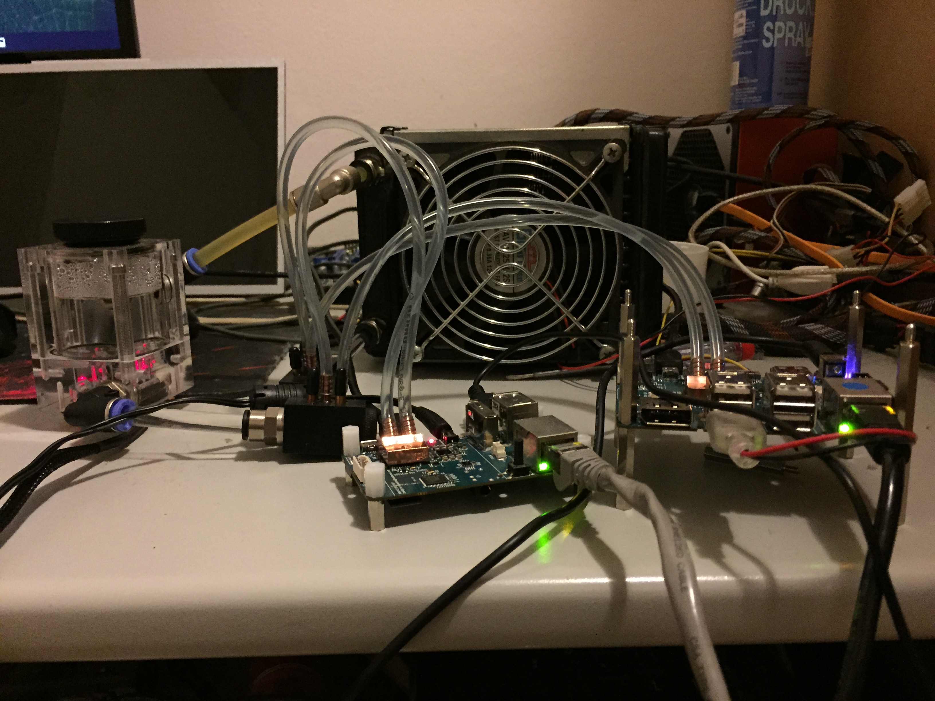
After finding some small 15x15x5mm heatsinks, I decided to create an ODROID cluster using water cooling in order to reduce its temperature and noise. I started with a single ODROID-XU4 to see if the small heatsinks were powerful enough to distribute heat away from the board. After the initial tests, I connected the cooling system to the rest of the cluster, as shown in the images.
Alphacool NeXxus Monsta 140 Radiator with NB-Blacksilent Pro PK2 (http://bit.ly/1Fi5yrA)
120mm radiator
8V pump with reservoir
Adjustable DC-DC step-up convertor to control the speed of the fan and pump
Figure 1 - The setup is not overly complicated if you want to go liquid cooling.
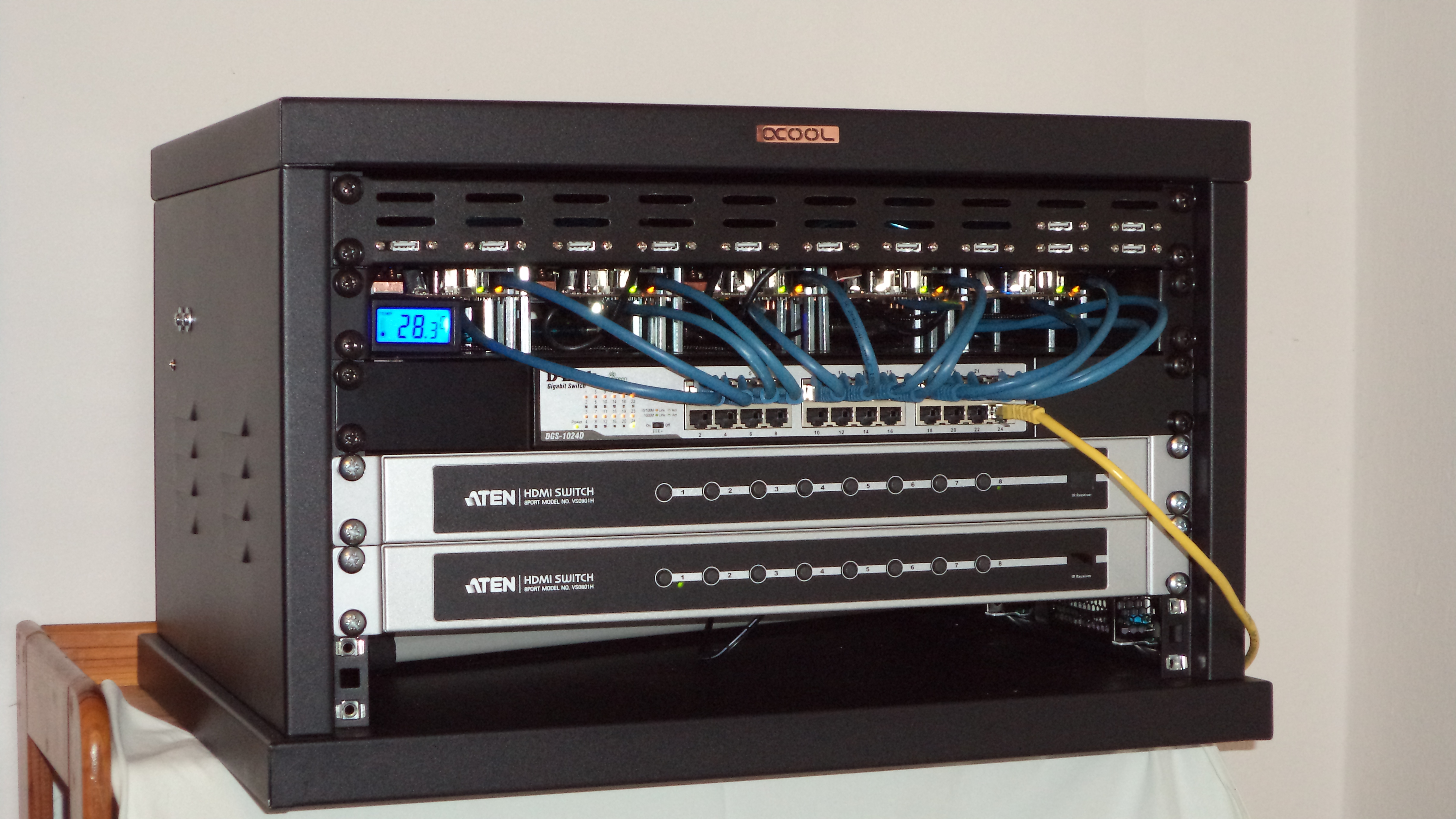
Cluster
10 x ODROID-U3
1 x ODROID-XU
1 x ODROID-XU4
2 x 5V 20A PSU
24 Port NW-Switch
2 x 8 Port-HDMI-Switch
Figure 2 - Here we see the Liquid cooled ODROIDS on a sweet setup as described above.
After filling the system, I had some problems with a leaky divider, but now it all runs fine. Using thermal paste instead of a thermal pad reduced the temperature by 5°C, and required custom fittings for the heatsink.
200TB GlusterFS Server: Using The ODROID-HC2 For Massively Distributed Applications
July 1, 2018By BaxterPadLinux, ODROID-HC2, Tinkering
Over the years, I have upgraded my home storage several times. Like many, I started with a consumer-grade NAS. My first was a Netgear ReadyNAS, then several QNAP devices. About a two years ago, I got tired of the limited CPU and memory of QNAP and devices like it, so I built my own using a Supermicro XEON D, Proxmox, and FreeNAS. It was great, but adding more drives was a pain. Migrating between ZRAID levels was basically impossible without lots of extra disks.
The fiasco that was FreeNAS 10 was the final straw. I wanted to be able to add disks in smaller quantities and I wanted better partial failure modes, kind of like unRAID, while remaining able to scale to as many disks as I wanted. I also wanted to avoid any single points of failure, such as a home bus adaptor, motherboard, or power supply.
I had been experimenting with GlusterFS and Ceph using roughly forty small virtual machines (VM) to simulate various configurations and failure modes such as power loss, failed disk, corrupt files, and so forth. In the end, GlusterFS was the best at protecting my data because even if GlusterFS was a complete loss, my data was mostly recoverable due to being stored on a plain ext4 filesystem on my nodes. Ceph did a great job too, but it was rather brittle (though recoverable) and difficult to configure.
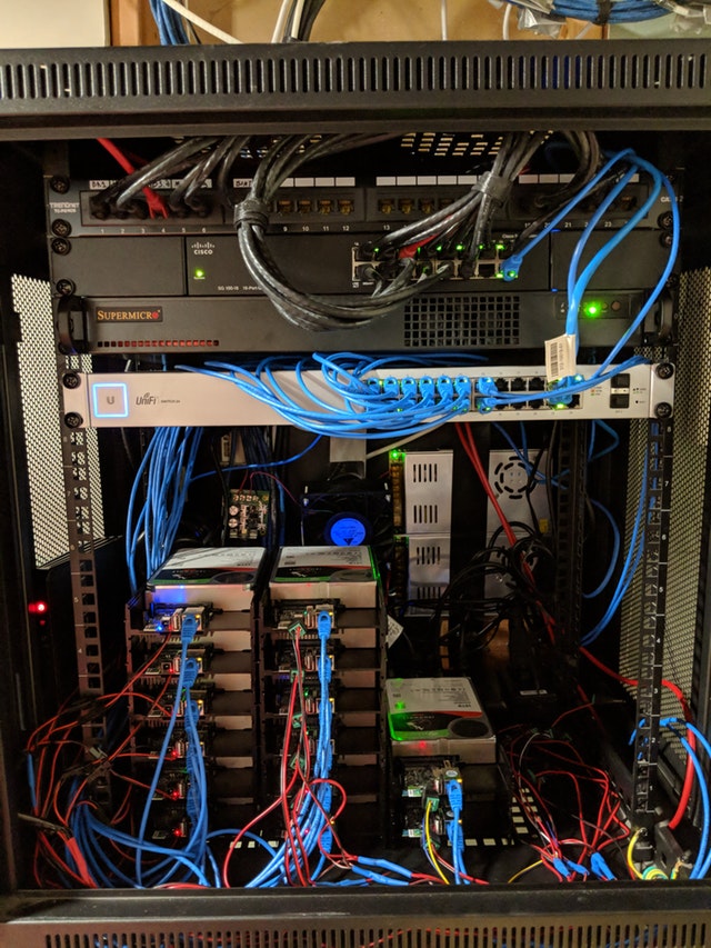
Enter the ODROID-HC2. With 8 cores, 2 GB of RAM, Gbit ethernet, and a SATA port it offers a great base for massively distributed applications. I grabbed four ODROIDs and started retesting GlusterFS. After proving out my idea, I ordered another 16 nodes and got to work migrating my existing array.
Figure 1 - This is a prime example of a cluster of ODROIDs handling real world data applications.
In a speed test, I can sustain writes at 8 GBPS and reads at 15 GBPS over the network when operations are sufficiently distributed over the filesystem. Single file reads are capped at the performance of 1 node, so ~910 Mbit read/write.
In terms of power consumption, with moderate CPU load and a high disk load (rebalancing the array), running a pfSense box, 3 switches, 2 Unifi Access Points, a Verizon Fios modem, and several VMs on the XEON-D host, the entire setup uses about 250 watts. Where I live, in New Jersey, that works out to about $350 a year in electricity. I'm writing this article because I couldn't find much information about using the ODROID-HC2 at any meaningful scale.
The crazy thing is that there isn't much configuration for GlusterFS. That’s what I love about it. It takes literally three commands to get GlusterFS up and running after you get the OS installed and disks formatted. I'll probably post a write up on my github at some point in the next few weeks. First, I want to test out Presto ( https://prestodb.io/), a distributed SQL engine, on these puppies before doing the write up.
July 1, 2018By Adrian PopaODROID-C1+, ODROID-C2, ODROID-N1, ODROID-XU4, Tutorial
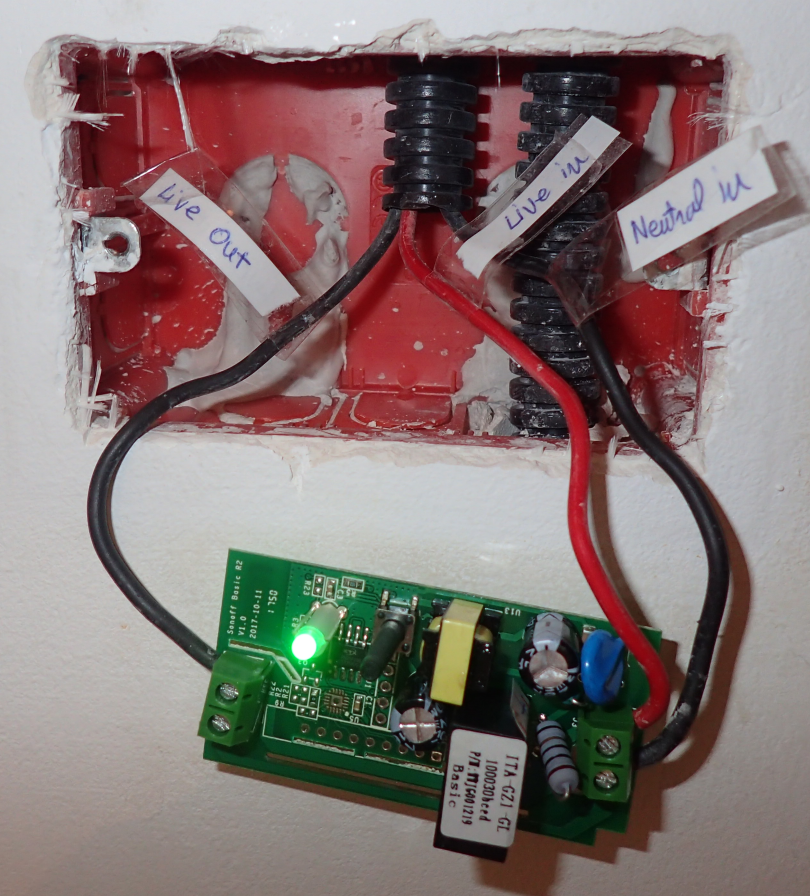
Ever since I started working with Home Assistant and automating various things around the house I wanted to have a way to control the lights. I looked at smart light bulbs, like Philips Hue, but they are expensive (about 12$/bulb - https://goo.gl/xiAqEe). Also, most solutions use proprietary protocols or cloud services which may leak personal data, or might stop working in the future leaving you with expensive paperweights. By accident, I heard about Sonoff wifi switches built by Itead (http://sonoff.itead.cc/en/products/sonoff/sonoff-basic). They combine an ESP8266 wifi-enabled microcontroller and a relay and let you turn things on and off from a distance. Apart from a low price (~5$ - https://goo.gl/WP31Ny), the microcontroller also exposes a few GPIOs and can be flashed with open source software to customize it.
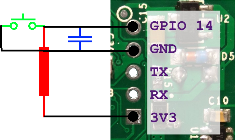
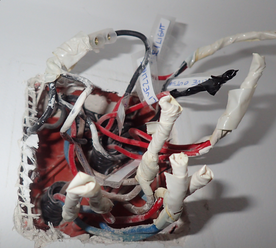
So, the plan was to get several Sonoff Basic switches, remove the case, flash Tasmota firmware (https://github.com/arendst/Sonoff-Tasmota/wiki) and find a way to interface it with my existing light switches. Itead also makes a wifi light switch I could have used (http://sonoff.itead.cc/en/products/residential/sonoff-touch), but is more expensive and I wanted to keep my existing switches. Thankfully I found this youtube guide with an idea on how to convert a basic switch in a light switch: https://www.youtube.com/watch?v=ab472a40-co. You basically need to power the Sonoff, connect its output to the light bulb/light circuit and connect the light switch to GPIO14 and GND pads, and you are in business.
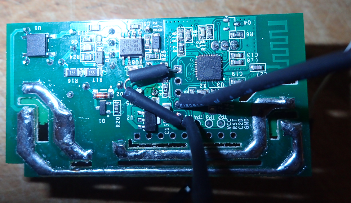
Flashing Tasmota
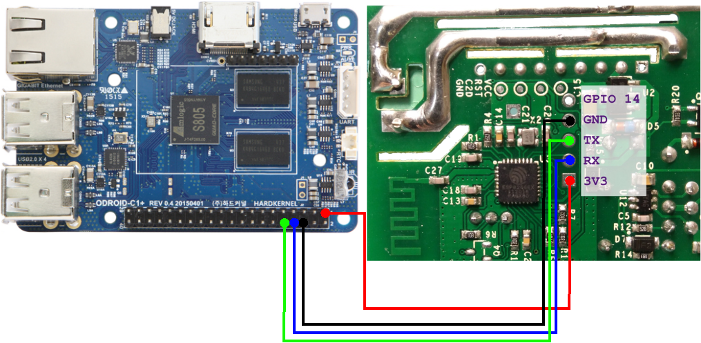
First thing you need to do is to open the Sonoff switch case (it is held in place by a few plastic clips) and identify the GPIO pads (see Figure 1). There you have a 3.3V square pad, UART RX and TX, the ground and the last one is GPIO14. In order to flash a new firmware you need to power the Sonoff, connect the UART to a device running Arduino and hold the button (GPIO0) while it boots to put it into programming mode. In order to do this, you can either solder a 5 pin header to the board or simply position the header so that it touches the pads while you flash (this is what I did). Note that during this operation the Sonoff will not be connected to the mains and will draw power from the UART cable! (details: https://goo.gl/5TUfz8). If you do not have a suitable USB-UART adapter around, you can use the UART pins from the 40 pin header on an ODROID-C1/C2 directly with jumper cables (see figure 1). Make sure to connect RX and TX crossed over so that RX on Odroid is connected to TX on Sonoff. Also, power must come from the 3.3V pin, not the 5V pin.
If you are using the ODROID-C2/N1, the arduino program will fail to run because it cannot find relevant 32bit libraries. You will need to install 32bit support in your ubuntu and then run the same steps as for ODROID-C1:
If you are using ODROID-XU4/N1, the steps are the same as above, but you will need to use a shifter shield to address the voltage difference between the ODROID and the ESP chip. For the C1 follow these steps:
$ unxz arduino-1.8.5-linuxarm.tar.xz
$ tar xvf arduino-1.8.5-linuxarm.tar
$ cd arduino-1.8.5
$ ./arduino
Allow it to start, then open Arduino IDE and select File -> Preferences and add the following text for field Additional Boards Manager URLs: https://goo.gl/EVq7nf and select OK. Next, open Tools -> Boards ... -> Boards Manager ... and scroll down and click on esp8266 by ESP8266 Community. Click the Install button to download and install the latest ESP8266 board software. Select Close. You can now close Arduino. In the following step you will download and install Tasmota firmware. You can get the latest version from here: https://github.com/arendst/Sonoff-Tasmota/releases
$ cd ..
$ wget https://goo.gl/KQwDvr
$ tar zxvf v5.13.1.tar.gz
$ cp -ar Sonoff-Tasmota-5.13.1/lib/* arduino-1.8.5/libraries/
$ cp -ar Sonoff-Tasmota-5.13.1/sonoff/ arduino-1.8.5/
$ cd arduino-1.8.5
$ ./arduino
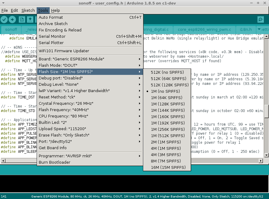
You can now open the Tasmota project by selecting File -> Open and locating and loading sonoff.ino from the sonoff directory under arduino-1.8.5. In the list of open tabs locate user_config.h, where you need to change the following settings. Note that changing settings here is not mandatory - most of them can be configured later through the web interface or MQTT, but once you reset to hardware defaults, these will be those defaults:
Set static IP address if desired (WIFI_IP_ADDRESS, WIFI_GATEWAY, WIFI_SUBNETMASK, WIFI_DNS)
Set SSID/Password for two access points (STA_SSID1, STA_PASS1, etc)
Set configuration tool to WIFI_RETRY (WIFI_CONFIG_TOOL), so that if it cannot connect to WiFi it will keep trying instead of becoming an access point. Otherwise some attacker could knock it off the WiFi network with a deauth attack (see https://goo.gl/76kYPs) and force it to become an access point and re-configure it.
Enable syslog if you have one (it helps debugging issues, though local logs will be preserved on the device, accessible through the web interface until reboot)
Disable (comment with //) MQTT TLS (//#define USE_MQTT_TLS)
Set MQTT broker IP, user, password (MQTT_HOST, MQTT_USER, MQTT_PASS)
Disable MQTT Retain (caused me some headaches) (MQTT_BUTTON_RETAIN, MQTT_POWER_RETAIN, MQTT_SWITCH_RETAIN)
Define a topic for MQTT messages (MQTT_TOPIC). Something like kids_light, or bedroom_light for example
Disable Domoticz if not needed (//#define USE_DOMOTICZ)
Set up a username and password for the web interface for a bit of protection (WEB_USERNAME, WEB_PASSWORD)
Disable mDNS discovery (//#define USE_DISCOVERY)
Set up NTP servers (NTP_SERVER1, etc)
Set up timezone (APP_TIMEZONE)
Disable I2C if not used (//#define USE_I2C)
Once your configuration is complete, you need to define flashing mode by making the changes defined here: https://goo.gl/NmnZBE in Arduino IDE. You will need to select /dev/ttyS2 as a port with 115200 baud-rate.
Figure 2 - user_config.h excerpt and flash settings
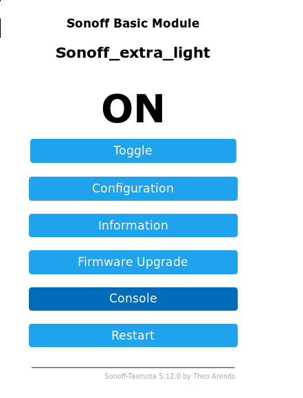
When done, insert the pin header in the Sonoff while holding the power button pressed and release the button when it has a steady connection. Start compile and flash (the second button with an arrow symbol in Arduino IDE) and wait for it to complete. If flashing fails, try again to put the Sonoff in programming mode and try again. After flashing is done, power up the Sonoff and it should connect to your desired WiFi. You can power it through the makeshift UART cable, or from the mains - but make sure to reassemble it if using the mains so that you do not risk getting shocked. You can find out its IP address (either static, or from DHCP) by consulting your router's client list. You can then connect via HTTP to its management address to configure it further.
Figure 3 - Web management
Tasmota configuration
Tasmota firmware is mostly built with MQTT in mind. MQTT is a machine to machine messaging protocol that we have discussed in a previous article (https://goo.gl/9ggqHJ). It allows integration of multiple entities with a message broker (we are using mosquitto), and also is well supported by Home Assistant. Tasmota firmware has many parameters you can configure via MQTT or REST API, (complete list here: https://github.com/arendst/Sonoff-Tasmota/wiki/Commands), but the most important ones can be configured via the web interface.
We will be configuring the following:
GPIO14 will have the same role as Switch1. To do this, you can navigate to the web interface, inside Configuration -> Configure Module:
Module Type: 01 Sonoff basic
GPIO14 sensor: 09 Switch1
If you have not configured MQTT in user_config.h yet, you can do so now by going into Configuration -> Configure MQTT and add the broker address and username/password.
If you are using passwords with MQTT, you will need to add the new account in mosquitto:
If you wait a second the Sonoff should connect to the MQTT broker and you should be able to control it from the command line. Assuming you are using a topic of bedroom_light you can turn on the switch with:
You can query the device for its settings or information through MQTT, but the replies will be sent to the syslog server so you need to keep an eye on it when issuing MQTT commands. To get the switch state run:
One extra thing you can configure is the ESP power management. It is disabled by default, but you can instruct it to go into 100ms sleeps to reduce power (and heat) with this command:
Make sure the code above uses the correct topics that you set for your device. You can restart Home Assistant and test that everything works as expected (you should be able to toggle the switch from Home Assistant, Tasmota's web interface and the button on the Sonoff).
The hardware build
In order to proceed and connect the light switch to GPIO14 we need to do some soldering and add a low-pass filter along with connector cables to GPIO14 and GND. The reason why we need a low-pass filter is because EM radiation will be picked up by the wires used (they act like an antenna) and may cause the switch to randomly toggle at times. To mitigate this you can use a low-pass filter so that only DC is allowed to pass and also you can twist the wires so that the interference cancels out (http://goo.gl/7zEPc9).
You can build a low-pass filter by following this guide (https://www.youtube.com/watch?v=aq8_os6g13s) with a 10k resistor and a 33pF capacitor. Exact values are not that important - you can use whatever you have.
Figure 4 - Schematic
Make sure the soldering is solid and use heat shrink tubing to isolate your components. When you are done test the unit taking care not to touch the exposed AC traces. You should also run some electric tape over it because we will not be using the plastic cover.
Figure 5 - Assembled unit
Attaching Sonoff to the lights
This step may be the trickiest one, because light wiring may differ from place to place and you may not have everything you need in one place. You may need to consult your electrician, the electrical code and local legislation before you proceed. Most importantly, make sure to turn off the breakers for lights and sockets before dismantling the light switch or you will risk death. You will also need a test light (https://en.m.wikipedia.org/wiki/Test_light) to identify the live wires.
Let us briefly analyze what wires run through your walls to power sockets and lights. You will have a "hot" wire (also known as "live") which has a voltage potential of 110/220V depending on where you live, a "neutral" wire which is used to complete the circuit and offer a path for the current to take (this is usually not energised) and a "ground" wire used in some electrical sockets as an emergency backup path for the neutral wire. In order to power the Sonoff we need a live and a neutral inside the light switch enclosure.
Unfortunately, not all wiring standards provide the neutral wire, so we might need to make one. In my case (and I suspect it is common for most Europe) the light switch has a live input that goes to two mechanical switches and that can continue with two independent live output wires that go up through the wall to my light fixture.
Figure 6 - Light diagram
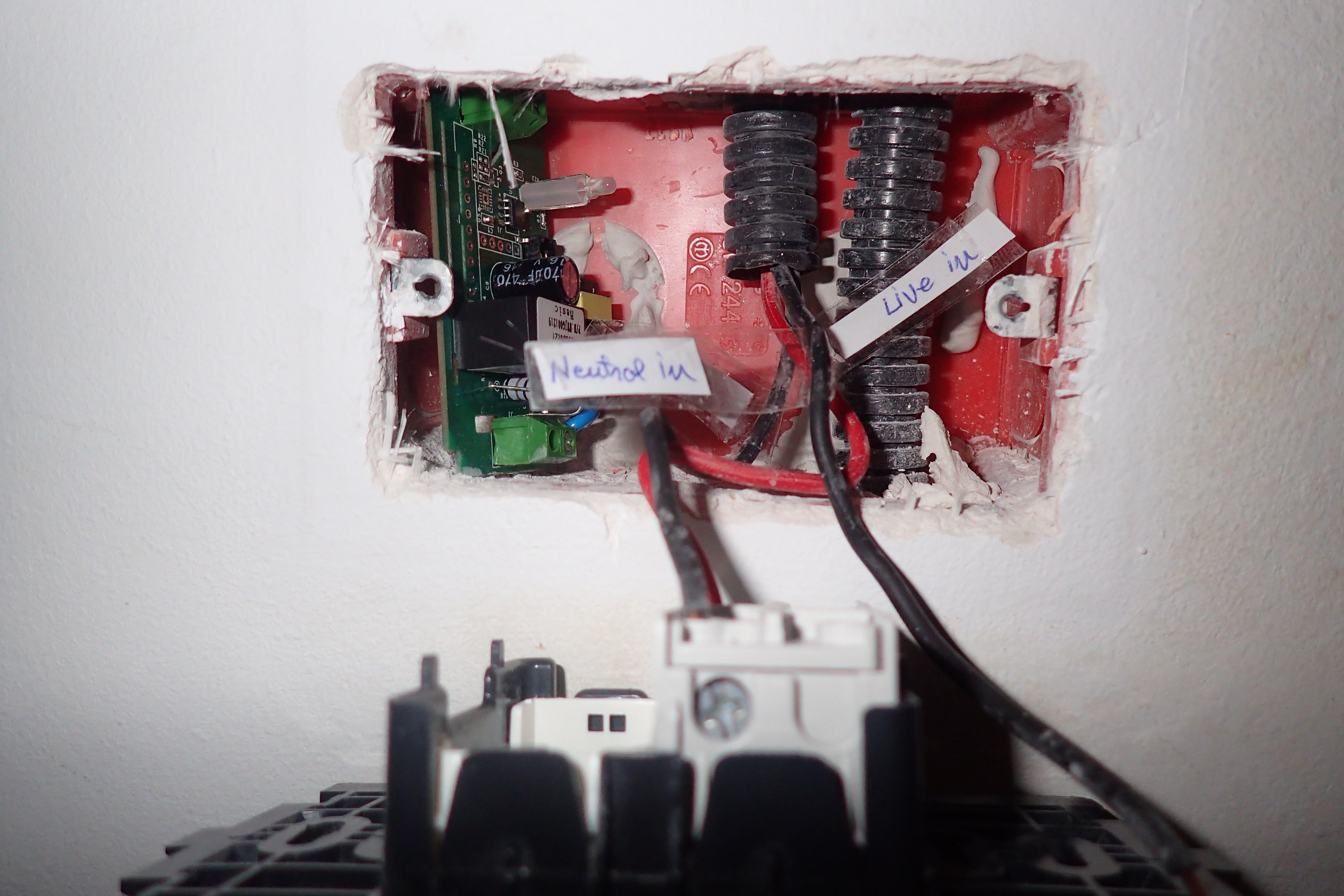
There is no neutral near the light switch. The neutral goes to the light fixture itself and closes the circuit through the lightbulb. Well, that will not do. We need to modify the circuit and suspend one live output and transform it into a neutral with a bit of wiring, mostly because I did not want to run another wire through the wall (difficult without skill/special tools).
The first thing you need to do is cut power to the breakers and remove your light switch from the wall to have a look at the wires. It might be a good idea to test and see if the Sonoff PCB fits inside the light switch electrical box (it will not fit in most Eastern European round electrical boxes). If it does not fit you need to be creative and find a place where to put it.
[ Figure 7 - Light box test and default wiring ]In my lightbox, as you can see in figure 7, I had only one live input going to both switches (red) and two live outputs going to the lightbulbs (black). You should take your time and identify each wire with a test light (when the breaker is on) and label the wires (with the breaker off, naturally).
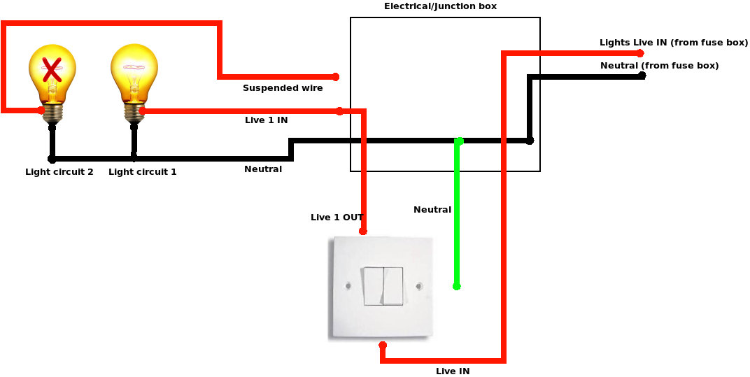
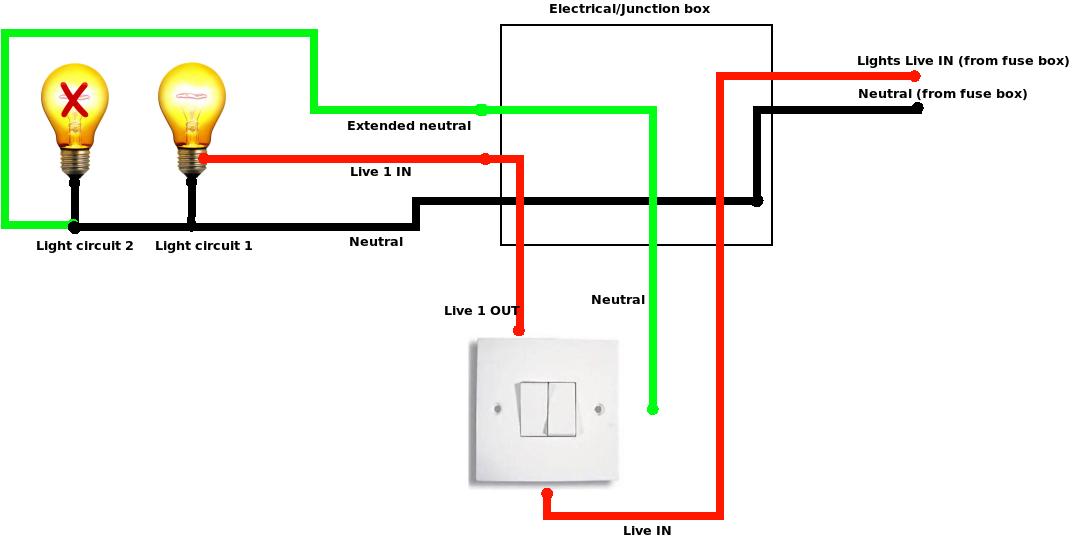
My plan is to convert a live output wire into a neutral input by disconnecting the output wire from the bulb and connecting it to neutral. By doing this I will not be able to use a light fixture with two independent lights, but I have a simple light fixture anyway, so it is no problem. There are two places where you can do this - in the intermediary electrical box (which should be close by, near the ceiling), or at the light fixture. Both wiring diagrams are presented in figure 8 and I will describe the steps needed for each variant.
Figure 8a - Wiring options - rewire at the junction box
Figure 8b - Wiring options - rewire at the light fixture
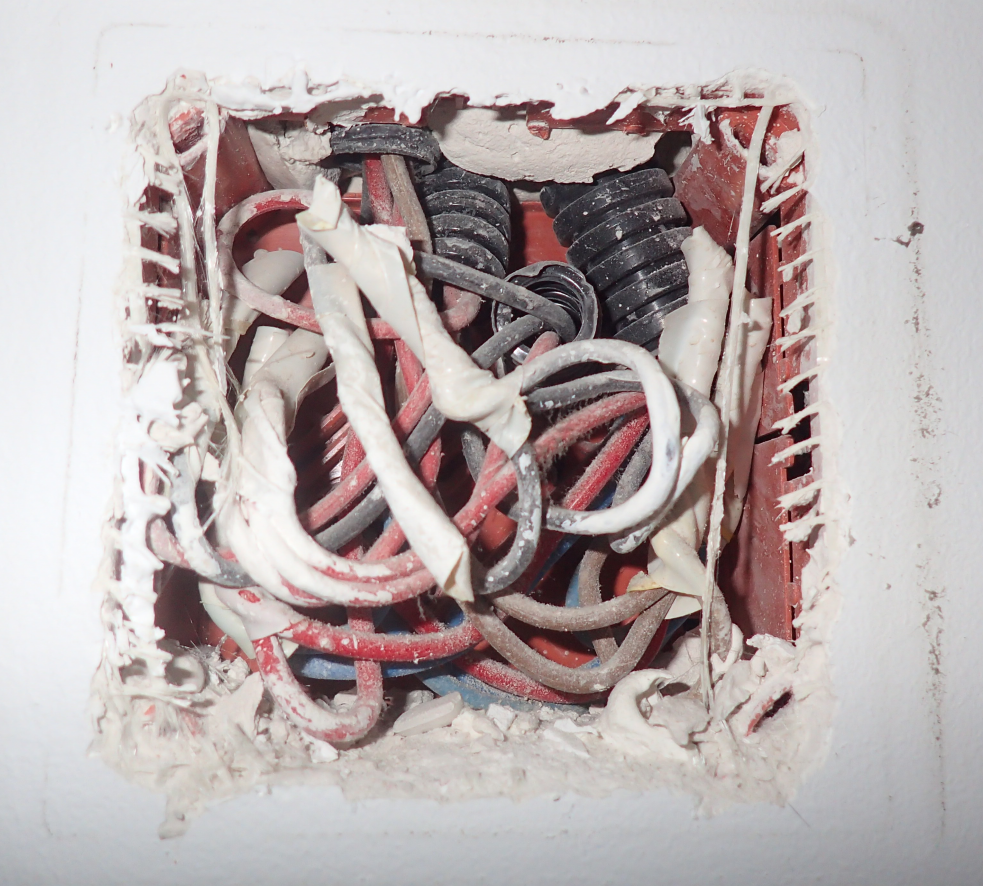
For the 8A option you need to have a look in the connection electrical box. This box should contain all electrical circuits that go to a room - lights and sockets. When you have a look inside (with the breaker off) you will probably see a jumbled mess of wires, like in figure 9. You need to identify (based on color and position) which wires go to your light switch and which go to the light bulb. You also need to chose which live output wire you want to convert to neutral and identify the top end of that wire in the electrical box. You can do this either by pulling on the wire and observing which wire moves, or by measuring the resistance of the wire ends (prolonged if needed) with an ohmmeter (resistance should be close to zero). Make sure to label all the wires you identify for future reference, in case you need to undo this mess later on.
Figure 9 - Electrical box - before
Next you need to identify a neutral wire in the electrical box. You should find two bigger bundles of wires with 3 or more wires connected together. One bundle connects all live wires (the one coming from the breaker with the one going to the light switch and the ones going to the sockets) and the other bundle will hold all the neutrals. You can find which is wich by identifying which is the hot wire going to your light switch, or by measuring them with a tester.
Now (with the breakers off) you need to disconnect the live output from the wire going to the bulb and connect it with the other neutrals. The remaining wire will be unconnected (but it is still a good idea to label and isolate its end).
Figure 10 - Electrical box - after
At this point you can connect the sonoff with live in and neutral in its input and live out in the output (with the breakers still off) and then test your setup.
Figure 11 - Live test
For the 8B option you do not need to make changes in the electrical box. I had to do this because the electrical box in my bedroom is not easily accessible. In this case we bring the neutral from the light fixture back to the light switch by connecting the neutral wire available in the light fixture directly to an old "live in" wire which we will call neutral from now on. Take great care with identifying which is the correct wire, otherwise if you directly connect neutral to the real live wire, you will create a short circuit and your fuse will blow/melt.
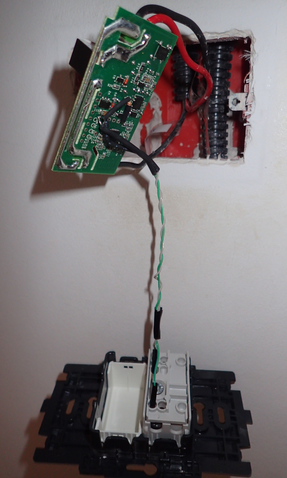
Like in the previous example you will need to connect live in and neutral in to the Sonoff's input and live out to the output (with the breakers off). Connect the lightswitch to GPIO14 and GND as well. After the tests are successful you will need to gently seat the sonoff inside the light switch electrical box and attach the light switch back to the wall and you are done.
Fig 12 - Final assembly
Automations
You should now have working light switches in Home Assistant that you can also toggle with the old mechanical switch, but it is not very impressive for the amount of work put in. Why did I want "smart" lights in the first place? Let us see.
Turn off the light after 30 minutes
Sometimes you might forget a light turned on when you leave for work. With network-enabled lights you can turn it off yourself, but that is not automation. In my case, the kids like to fall asleep with the lights on (despite the night light) so we always had to turn it off once they were asleep. If they awoke in the middle of the night they would still turn it on and go back to sleep. So, an elegant way to fix this is to create an automation that between a certain time interval (23:00-17:00) turns off the lights after they have been on for 30 minutes. You need to edit automations.yaml and add the following two automations:
- action:
- data:
entity_id: light.kids_light
service: homeassistant.turn_off
alias: Turn off Kids Light after 30 min inactivity
condition:
- after: '23:00'
before: '17:30'
condition: time
id: '1525335992266'
trigger:
- entity_id: light.kids_light
for:
minutes: 30
platform: state
to: 'on'
- action:
- data:
entity_id: light.kids_light
service: homeassistant.turn_off
alias: Turn off Kids Light at 23:00
condition: []
id: '1525343566208'
trigger:
- at: '23:00'
platform: time
The first automation listens for state changes that happen when the light turns on and if it is in the required time interval waits for 30 minutes to pass before turning it off. The second automation handles the case where light is turned on at 22:00 let us say and the previous automation will not have effect (the state change needs to happen during 23:00-17:00) - so it is lights out at 23:00. You can improve this automation and have it check if somebody is home/in the room, or operate only when the sun is up, etc.
Disable the hardware switch
If you had small children you would have noticed that there is a period in their development when they need to push all the buttons. If they get hold of the light switch they will toggle it on and off till it breaks. To prevent that you can now lock the mechanical light switch so that it will not toggle the light when pressed. Simply set GPIO14 to none in the configuration. You can do this over MQTT and it will cause the sonoff to reboot (light flickers for ~250 ms). You can create the following scripts in Home Assistant, inside scripts.yaml:
When you call the script (either from the Services menu or from a dashboard) the lights will lock or unlock and you can control them only over wifi.
Wakeup call
The last application is more sinister. If you have heavy sleepers in your family that need convincing to be woken up, how about using the US Military Bugle wake up call (https://www.youtube.com/watch?v=xt4hSs4IWPg)? Apart from sound we will also make the light flash with the same pattern as the music. That should be annoying.
You can start by downloading the audio and converting it to mp3:
I am using MPD as a media player controlled by Home Assistant, so make sure to move the MP3 file somewhere in MPD's media library path, so it can be played (typically inside /var/lib/mpd/music/). You will also need to add it to a saved playlist (I used "wakeupalarm" as a name).
Next we need to produce some rhythm information. It should correspond to on and off signals to the light bulb. My idea was to "type" the rhythm on the keyboard as I am listening to sound so that a key press/hold represents light on, a key release represents light off. We can use evtest to select the keyboard and log the duration and sequence of key presses:
Once done, the file should contain lines like the following, recording key up/down events for the letter "A":
Event: time 1525422859.108421, -------------- SYN_REPORT ------------
Event: time 1525422859.204406, type 4 (EV_MSC), code 4 (MSC_SCAN), value 70004
Event: time 1525422859.204406, type 1 (EV_KEY), code 30 (KEY_A), value 1
Event: time 1525422859.204406, -------------- SYN_REPORT ------------
Event: time 1525422859.300420, type 4 (EV_MSC), code 4 (MSC_SCAN), value 70004
Event: time 1525422859.300420, type 1 (EV_KEY), code 30 (KEY_A), value 0
The file trumpet.txt will be your rhythm file and needs to be copied to /home/homeassistant/.homeassistant/. You can also get my interpretation of it from here: https://goo.gl/cFpLbs.
Now we can build an appdaemon app (described in this previous article: https://goo.gl/npGqoX) that when triggered by an input boolean, instructs MPD to start playing the trumpet and parses the rhythm text file and issues the corresponding on/off commands to the light. You can get the app and its configuration from here (built for appdaemon 3.x): https://goo.gl/Kn7PLK.
$ cd /home/homeassistant/.homeassistant/apps
$ wget -O sound_and_light_alarm.py https://goo.gl/aNuUB6
Adjust the following configuration to match your environment (changes done in apps/sound_and_light_alarm.yaml):
You can add the following boolean to Home Assistant (configuration.yaml):
input_boolean:
wake_up:
name: Wake up
initial: off
And the following automation will trigger it when you need to - for example during weekdays, at 7:00 (automations.yaml):
- id: '1527938039163'
alias: Wake up alarm
trigger:
- at: 07:00
platform: time
condition:
condition: time
weekday:
- mon
- tue
- wed
- thu
- fri
action:
- data:
entity_id: input_boolean.wakeup
service: input_boolean.turn_on
You can see it in action here: https://www.youtube.com/watch?v=ac9xnA6Y918. From the outside it looks like your house is trying to communicate via morse code with an alien mothership, but hopefully it will get the heavy sleepers up and running.
Troubleshooting
If you find yourself that lights turn off (or on) apparently at random there may be several things going on. In my case my lights would sometimes lose TCP connectivity to the MQTT server and would reestablish a new connection. Once the connection was up it would read the state from the MQTT server and would override the local state. If you are using the "retain" option inconsistently, this leads to problems such as an open light would turn off after a reconnection. In this cases it is best to disable MQTT retention and rely on local state of the switch. This means that if the light is on and there is a power outage, the light will come on when the outage is restored and you will not be able to force it off through MQTT while the light is unpowered. More details can be found at: https://goo.gl/ECUqRY.
One more problem you might face is that when you restart Home Assistant your light entities default to "off", even if a light is on. In order to fix this you can instruct Home Assistant to "ask" all the lights what their state is with the following automation (add to automations.yaml):
- action:
- data:
topic: cmnd/sonoffs/POWER
service: mqtt.publish
alias: Get Sonoff states on restart
condition: []
id: '1518951376931'
trigger:
- event: start
platform: homeassistant
Hopefully this article helps you implement a smart light system without too much cost or vendor lock-in.
Getting Started With OpenCL: Using The ODROID-XU4
July 1, 2018By cnxsoftLinux, ODROID-XU4
While I tested OpenGL ES with tools like glmark2-es2 and es2gears, as well as WebGL demos in Chromium, I did not test OpenCL, since I’m not that familiar with it, except it’s used for GPGPU (General Purpose GPU) to accelerate tasks like image/audio processing. That was a good excuse to learn a bit more, try it out on the board, and write a short guide to get started with OpenGL on hardware with Arm Mali GPU. The purpose of this tutorial is to show how to run an OpenCL sample, and OpenCL utility, and I won’t go into the nitty gritty of OpenCL code. If you want to learn more about OpenCL coding on Arm, one way would be to check out the source code of the provided samples.
Arm Compute Library and OpenCL Samples
Since I did not know where to start, Hardkernel redirected me to a forum thread where we are shown how to use Arm Compute Library to test OpenCL on the board. The relevant post is dated January 2018, and relies on Compute Library 17.12, but you can check out the latest version and documentation here, https://arm-software.github.io/ComputeLibrary/latest/. The latest version is 18.03 at the time of writing this post, so I retrieved it, and tried to build it as instructed:
Looking at the kernel log with dmesg, it was clear the board ran out of memory: “Out of memory: Kill process 4984 (cc1plus) Out of memory: Kill process 4984 (cc1plus)“. So I had to setup a swap file (1GB):
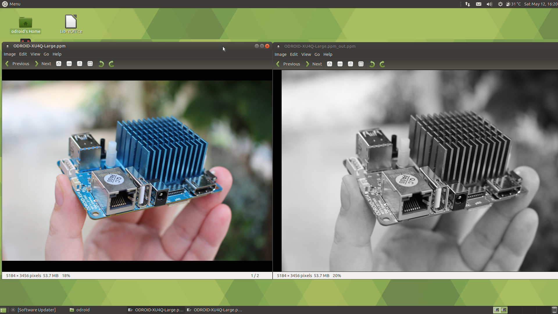
All samples have also been built and can be found in the build/examples directory. I ran cl_convolution after generating a Raw ppm image using Gimp:
$ time ./cl_convolution ~/ODROID-XU4Q-Large.ppm
$ ./cl_convolution

Test passed

real 0m5.814s
user 0m4.893s
sys 0m0.758s
It processed the photo (5184 x 3456) in less than 6 seconds. If we look at the resulting image, we can see the grayscale output from the OpenCL convolution, as shown in Figure 1.
Figure 01 - Original Image (Left) vs After OpenCL Convolution (Right)
I’ve repeated a similar operation with convert which has not been compiled with OpenCL support, using software only:
$ time convert ODROID-XU4Q-Large.ppm -colorspace Gray ODROID-XU4Q-Large-Grayscale.ppm

real 0m10.475s
user 0m0.724s
sys 0m2.957s
It took a little over 10 seconds, so almost twice the time used by the OpenCL demo. The PPM image files are however over 50MB, so part of the time is used to read and save the file from the eMMC flash. Repeating the tests provide similar performance (~6s vs ~11s), so it may be negligible. The “convert version” command’s output showing OpenCL is not part of the enabled features in ImageMagick:
$ time ./cl_events ~/ODROID-XU4Q-Large.ppm
$ ./cl_events

Test passed

real 0m3.068s
user 0m2.527s
sys 0m0.369s
What did it do? When I open the file it looks the same of the first sample (Grayscale image), but it actually scaled the image (50% width, 50% height):
The last sample cl_sgemm manipulates matrices. The main goal of the three OpenCL (cl_xxx_ samples) is to show how to use OpenCL Convolution, Events and SGEMM (Single-precision GEneral Matrix Multiply) using the Compute Library. You can also play with other samples for NEON and OpenGL ES, and ARM Community published a blog post explaining how to run neon_cartoon_effect on Raspberry Pi , and explaining the source code in details. You don’t actually need an RPi board for that since any ARM board with a processor supporting NEON should work.
clinfo Utility
clinfo is a utility that print information about OpenCL platforms and devices in the system, https://github.com/Oblomov/clinfo, which is easily installed:
$ sudo apt install clinfo
However, running the program does not return any useful information:
$ clinfo
Number of platforms 1
Platform Name ARM Platform
Platform Vendor ARM
Platform Version OpenCL 1.2 v1.r12p0-04rel0.03af15950392f3702b248717f4938b82
Platform Profile FULL_PROFILE
Platform Extensions cl_khr_global_int32_base_atomics cl_khr_global_int32_extended_atomics cl_khr_local_int32_base_atomics cl_khr_local_int32_extended_atomics cl_khr_byte_addressable_store cl_khr_3d_image_writes cl_khr_fp64 cl_khr_int64_base_atomics cl_khr_int64_extended_atomics cl_khr_fp16 cl_khr_gl_sharing cl_khr_icd cl_khr_egl_event cl_khr_egl_image cl_arm_core_id cl_arm_printf cl_arm_thread_limit_hint cl_arm_non_uniform_work_group_size cl_arm_import_memory
Platform Extensions function suffix ARM

Platform Name ARM Platform
Number of devices 2
Device Name Mali-T628
Device Vendor ARM
Device Vendor ID 0x6200010
Device Version OpenCL 1.2 v1.r12p0-04rel0.03af15950392f3702b248717f4938b82
Driver Version 1.2
Device OpenCL C Version OpenCL C 1.2 v1.r12p0-04rel0.03af15950392f3702b248717f4938b82
Device Type GPU
Device Profile FULL_PROFILE
Device Available Yes
Compiler Available Yes
Linker Available Yes
Max compute units 4
Max clock frequency 600MHz
Device Partition (core)
Max number of sub-devices 0
Supported partition types None
Max work item dimensions 3
Max work item sizes 256x256x256
Max work group size 256
Preferred work group size multiple 4
Preferred / native vector sizes
char 16 / 16
short 8 / 8
int 4 / 4
long 2 / 2
half 8 / 8 (cl_khr_fp16)
float 4 / 4
double 2 / 2 (cl_khr_fp64)
Half-precision Floating-point support (cl_khr_fp16)
Denormals Yes
Infinity and NANs Yes
Round to nearest Yes
Round to zero Yes
Round to infinity Yes
IEEE754-2008 fused multiply-add Yes
Support is emulated in software No
Single-precision Floating-point support (core)
Denormals Yes
Infinity and NANs Yes
Round to nearest Yes
Round to zero Yes
Round to infinity Yes
IEEE754-2008 fused multiply-add Yes
Support is emulated in software No
Correctly-rounded divide and sqrt operations No
Double-precision Floating-point support (cl_khr_fp64)
Denormals Yes
Infinity and NANs Yes
Round to nearest Yes
Round to zero Yes
Round to infinity Yes
IEEE754-2008 fused multiply-add Yes
Support is emulated in software No
Address bits 64, Little-Endian
Global memory size 2090397696 (1.947GiB)
Error Correction support No
Max memory allocation 522599424 (498.4MiB)
Unified memory for Host and Device Yes
Minimum alignment for any data type 128 bytes
Alignment of base address 1024 bits (128 bytes)
Global Memory cache type Read/Write
Global Memory cache size 131072 (128KiB)
Global Memory cache line size 64 bytes
Image support Yes
Max number of samplers per kernel 16
Max size for 1D images from buffer 65536 pixels
Max 1D or 2D image array size 2048 images
Max 2D image size 65536x65536 pixels
Max 3D image size 65536x65536x65536 pixels
Max number of read image args 128
Max number of write image args 8
Local memory type Global
Local memory size 32768 (32KiB)
Max number of constant args 8
Max constant buffer size 65536 (64KiB)
Max size of kernel argument 1024
Queue properties
Out-of-order execution Yes
Profiling Yes
Prefer user sync for interop No
Profiling timer resolution 1000ns
Execution capabilities
Run OpenCL kernels Yes
Run native kernels No
printf() buffer size 1048576 (1024KiB)
Built-in kernels
Device Extensions cl_khr_global_int32_base_atomics cl_khr_global_int32_extended_atomics cl_khr_local_int32_base_atomics cl_khr_local_int32_extended_atomics cl_khr_byte_addressable_store cl_khr_3d_image_writes cl_khr_fp64 cl_khr_int64_base_atomics cl_khr_int64_extended_atomics cl_khr_fp16 cl_khr_gl_sharing cl_khr_icd cl_khr_egl_event cl_khr_egl_image cl_arm_core_id cl_arm_printf cl_arm_thread_limit_hint cl_arm_non_uniform_work_group_size cl_arm_import_memory

Device Name Mali-T628
Device Vendor ARM
Device Vendor ID 0x6200010
Device Version OpenCL 1.2 v1.r12p0-04rel0.03af15950392f3702b248717f4938b82
Driver Version 1.2
Device OpenCL C Version OpenCL C 1.2 v1.r12p0-04rel0.03af15950392f3702b248717f4938b82
Device Type GPU
Device Profile FULL_PROFILE
Device Available Yes
Compiler Available Yes
Linker Available Yes
Max compute units 2
Max clock frequency 600MHz
Device Partition (core)
Max number of sub-devices 0
Supported partition types None
Max work item dimensions 3
Max work item sizes 256x256x256
Max work group size 256
Preferred work group size multiple 4
Preferred / native vector sizes
char 16 / 16
short 8 / 8
int 4 / 4
long 2 / 2
half 8 / 8 (cl_khr_fp16)
float 4 / 4
double 2 / 2 (cl_khr_fp64)
Half-precision Floating-point support (cl_khr_fp16)
Denormals Yes
Infinity and NANs Yes
Round to nearest Yes
Round to zero Yes
Round to infinity Yes
IEEE754-2008 fused multiply-add Yes
Support is emulated in software No
Single-precision Floating-point support (core)
Denormals Yes
Infinity and NANs Yes
Round to nearest Yes
Round to zero Yes
Round to infinity Yes
IEEE754-2008 fused multiply-add Yes
Support is emulated in software No
Correctly-rounded divide and sqrt operations No
Double-precision Floating-point support (cl_khr_fp64)
Denormals Yes
Infinity and NANs Yes
Round to nearest Yes
Round to zero Yes
Round to infinity Yes
IEEE754-2008 fused multiply-add Yes
Support is emulated in software No
Address bits 64, Little-Endian
Global memory size 2090397696 (1.947GiB)
Error Correction support No
Max memory allocation 522599424 (498.4MiB)
Unified memory for Host and Device Yes
Minimum alignment for any data type 128 bytes
Alignment of base address 1024 bits (128 bytes)
Global Memory cache type Read/Write
Global Memory cache size 131072 (128KiB)
Global Memory cache line size 64 bytes
Image support Yes
Max number of samplers per kernel 16
Max size for 1D images from buffer 65536 pixels
Max 1D or 2D image array size 2048 images
Max 2D image size 65536x65536 pixels
Max 3D image size 65536x65536x65536 pixels
Max number of read image args 128
Max number of write image args 8
Local memory type Global
Local memory size 32768 (32KiB)
Max number of constant args 8
Max constant buffer size 65536 (64KiB)
Max size of kernel argument 1024
Queue properties
Out-of-order execution Yes
Profiling Yes
Prefer user sync for interop No
Profiling timer resolution 1000ns
Execution capabilities
Run OpenCL kernels Yes
Run native kernels No
printf() buffer size 1048576 (1024KiB)
Built-in kernels
Device Extensions cl_khr_global_int32_base_atomics cl_khr_global_int32_extended_atomics cl_khr_local_int32_base_atomics cl_khr_local_int32_extended_atomics cl_khr_byte_addressable_store cl_khr_3d_image_writes cl_khr_fp64 cl_khr_int64_base_atomics cl_khr_int64_extended_atomics cl_khr_fp16 cl_khr_gl_sharing cl_khr_icd cl_khr_egl_event cl_khr_egl_image cl_arm_core_id cl_arm_printf cl_arm_thread_limit_hint cl_arm_non_uniform_work_group_size cl_arm_import_memory

NULL platform behavior
clGetPlatformInfo(NULL, CL_PLATFORM_NAME, ...) ARM Platform
clGetDeviceIDs(NULL, CL_DEVICE_TYPE_ALL, ...) Success [ARM]
clCreateContext(NULL, ...) [default] Success [ARM]
clCreateContextFromType(NULL, CL_DEVICE_TYPE_DEFAULT) Success (1)
Platform Name ARM Platform
Device Name Mali-T628
clCreateContextFromType(NULL, CL_DEVICE_TYPE_CPU) No devices found in platform
clCreateContextFromType(NULL, CL_DEVICE_TYPE_GPU) Success (2)
Platform Name ARM Platform
Device Name Mali-T628
Device Name Mali-T628
clCreateContextFromType(NULL, CL_DEVICE_TYPE_ACCELERATOR) No devices found in platform
clCreateContextFromType(NULL, CL_DEVICE_TYPE_CUSTOM) No devices found in platform
clCreateContextFromType(NULL, CL_DEVICE_TYPE_ALL) Success (2)
Platform Name ARM Platform
Device Name Mali-T628
Device Name Mali-T628

ICD loader properties
ICD loader Name OpenCL ICD Loader
ICD loader Vendor OCL Icd free software
ICD loader Version 2.2.11
ICD loader Profile OpenCL 2.1
That’s a lot of information, and it shows one platform with two OpenCL devices (both Mali-T628) supporting OpenCL 1.2.
That’s all for this little getting started guide. If you actually want to make something with OpenCL, it’s time to read Arm Compute Library documentation, and other resources on the web.
Building a liquid-cooled ODROID took about 5 weeks to complete, with an average of 12-18 hours a day spent working on the project. It weighs a whopping 6.5lbs, with a total cost of around $950, including the board, accessories, cooling hardware, and shipping,
Wiring
Wiring the 18 connections for the 6 fans took almost 2 days to determine how to get the brackets to be perfect. Many hours were spent cutting wires and re-soldering new connectors as well as making them shorter. The power supply proved to be a project in itself. I needed to provide 12v, 5v, 3.3v, and 1.2v to all of the various diff connectors and had to fit 15 connections into the smallest space possible, while still dishing out the various different voltages, along with placing capacitors and resistors.
Figure 1 - Wiring of the liquid cooled ODROID
Breadboard
I found that using a breadboard permanently, rather than soldering up a new PCB, was actually better, since it had a deep base already and can be changed quickly if needed. The main input is a breadboard Arduino power supply, which gave me 5v/3.3v without having to use voltage regulators. I just soldered new leads to the bottom of the input board at the main 12v jack in order to bypass the board and rails, which gave the center of the board the 12v needed for the fans, pump, and LED bars.
Figure 2 - All pumps and cooling are cooling this machine perfectly
Fan and pump
I added a fan controller to tone down the fans and lights when I want it to run it silent and dim. The main UV led strip and fans are connected to the fan controller that gears the voltage down to approximately 6v, which keeps the fans just barely spinning but dead silent. I used a polycarbonate bullet-proof plexiglass as the base, then ran a multicolor LED through a hole that I drilled and installed a switch for selecting the color for the base. The pump runs at a constant 12v and seems perfect for the pressure required, so I didn’t bother implementing the pump that into the fan controller loop. The pump’s instructions state that it can run as low as 6v, but I determined that the bottleneck at my radiator could be overcome by pushing the pump at full strength. The pump is quiet and worked out well.
Figure 3 - With this setup this ODROID works perfectly even under extreme stress tests
Enhancements
I have ideas for a better setup, but can’t really afford to do another one for some time. I think that I can cool the XU-E significantly more, but for now I’ve shown that the concept works and runs solidly. Although the project could have been built for much less money, I wanted to use high end parts to give it a more polished look.
Hardware
Alphacool DC-LT Ceramic 12V DC Pump + Plexi Top
Alphacool NexXxoS XT45 Full Copper Triple 40mm Radiator with 6 fans in a push/pull configuration.
12V fans are 40mmx10mm running at ~6000rpm pushing ~9.5cfm
3/8ID 5/8OD tubing, aside from the 1/4ID to 3/8OD tubing to convert down to the radiator. Only 2 types of 40mm radiator are made, and there are no options for anything except 1/4ID on this breed, so I needed to use a bunch of extra fittings in order to convert it down
Bitspower, Enzotech, and Koolance connectors
Monsoon Free Center compression fittings for the tubing
XSPC LCD temp display with temp sensor for reservoir
FrozenQ Flex tank reservoir
Fesser One UV Blue Non-Conductive Coolant
Fujipoly Extreme Builder Thermal Pad 11.0W/mk
Darkside UV LED strips
The rest of the parts were o-rings and lighting, as well as various other accessories needed for the power supply setup. The base is an old Macintosh CPU heatsink I found. The rest of the project is mostly held together by an older Erector set that I disassembled. The rubber feet are salvaged from a Playstation controller.


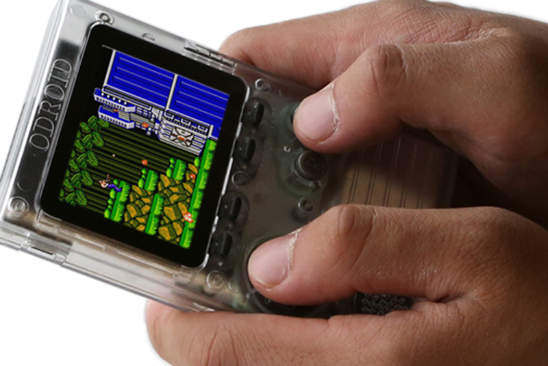


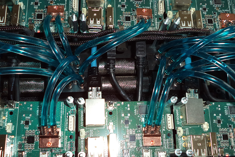


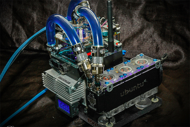

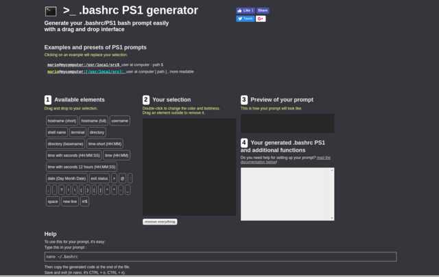
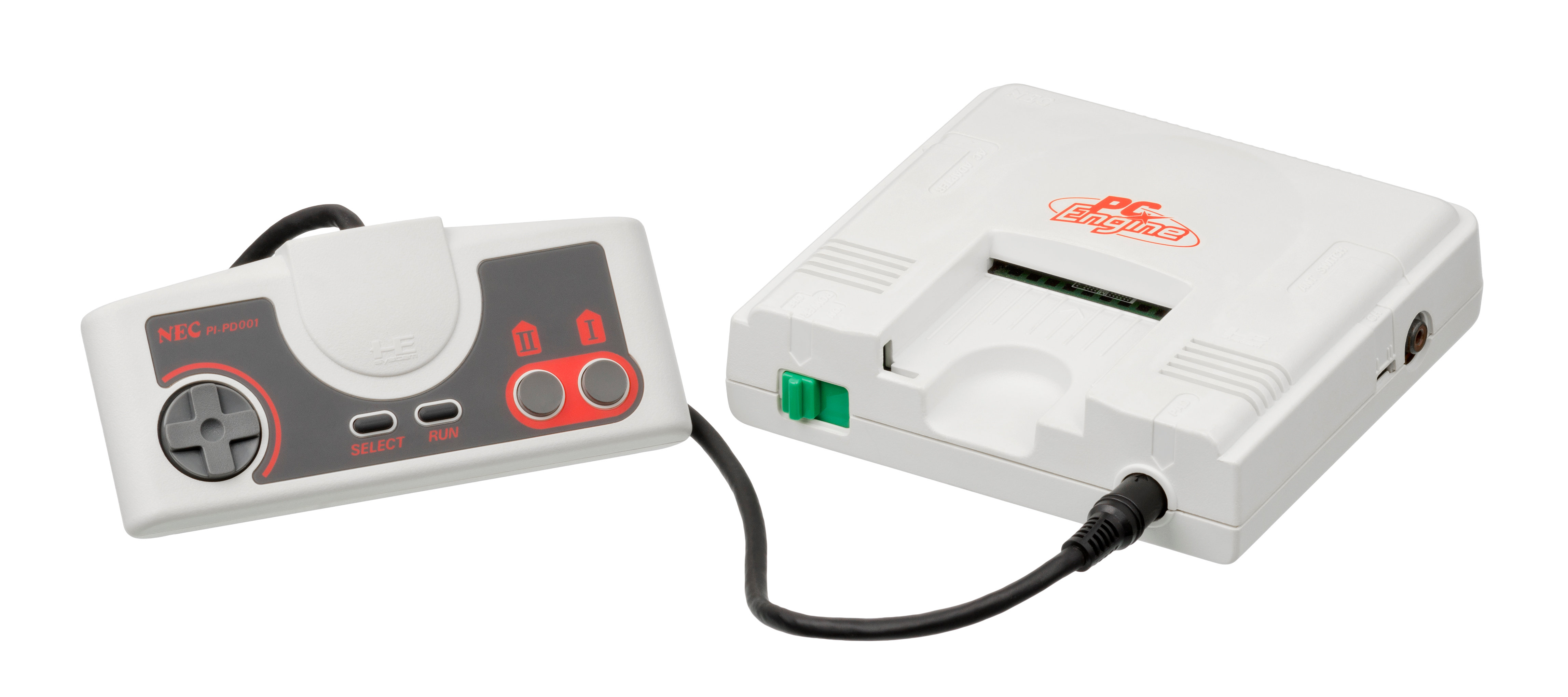
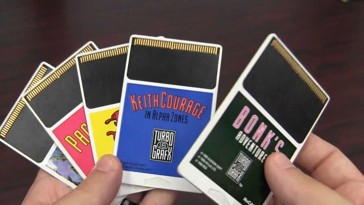
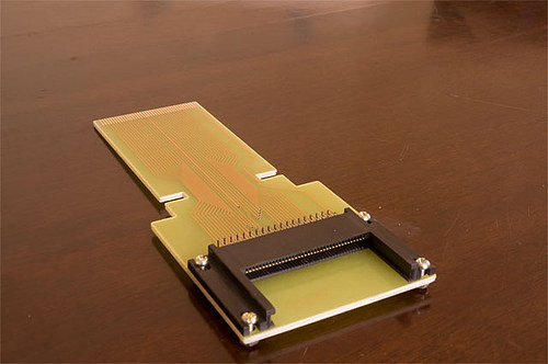
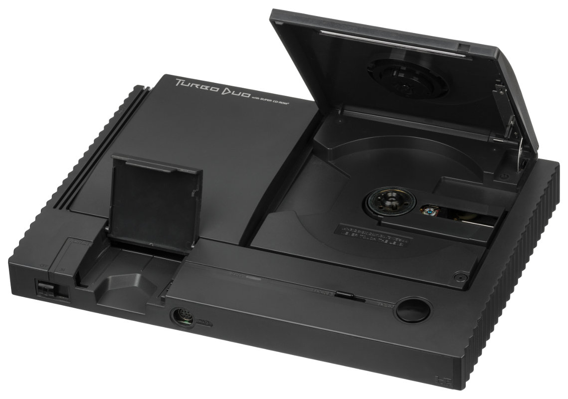

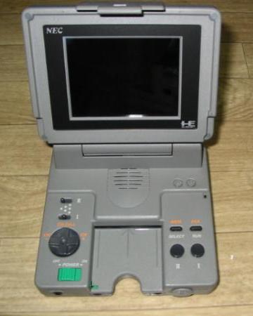
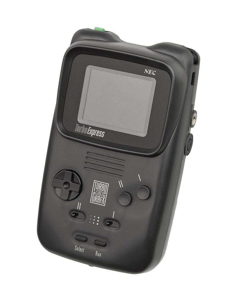
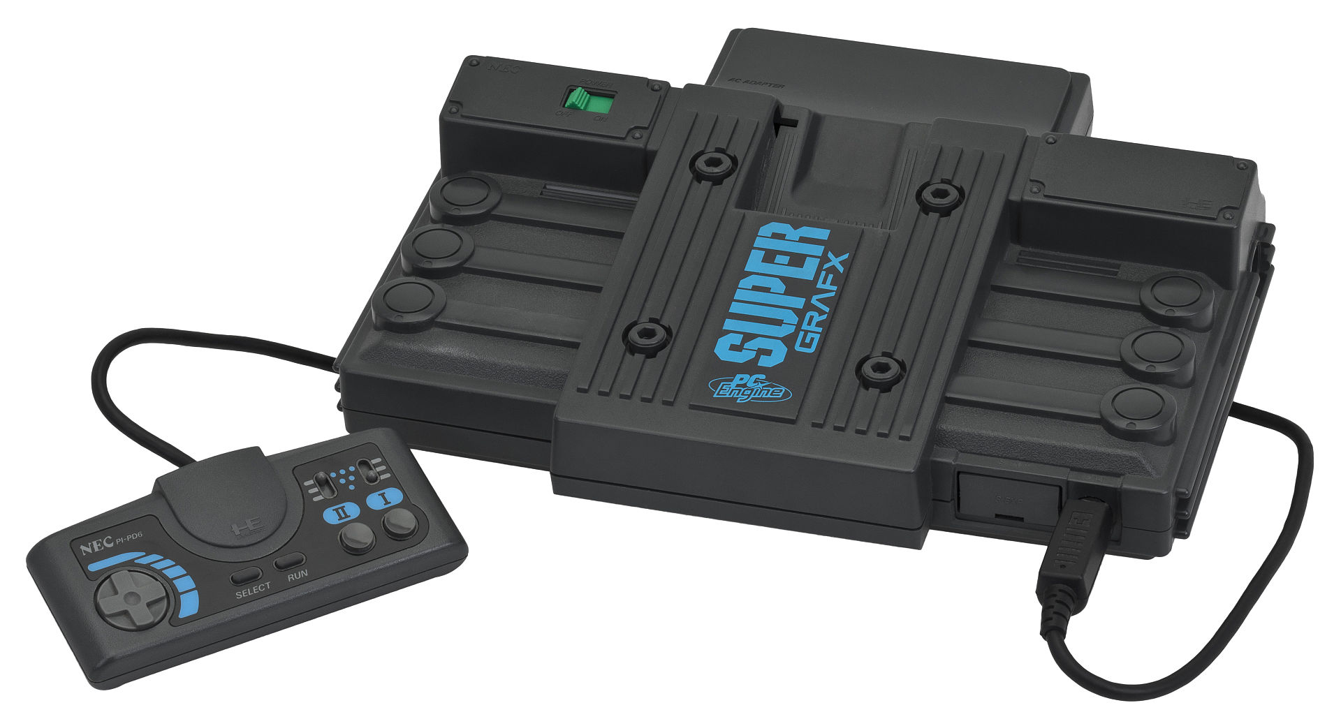
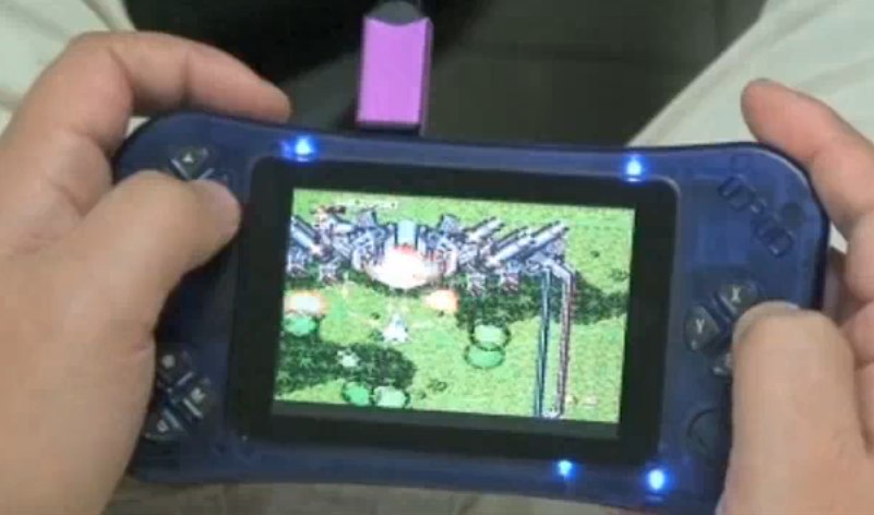
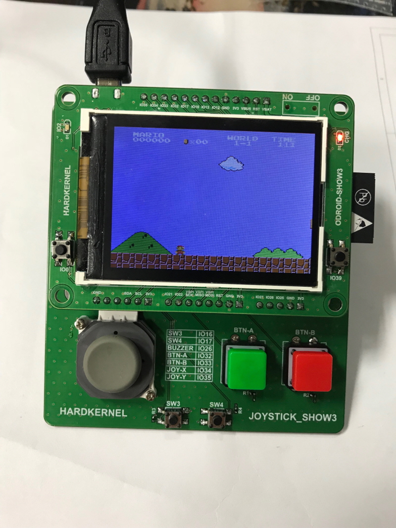

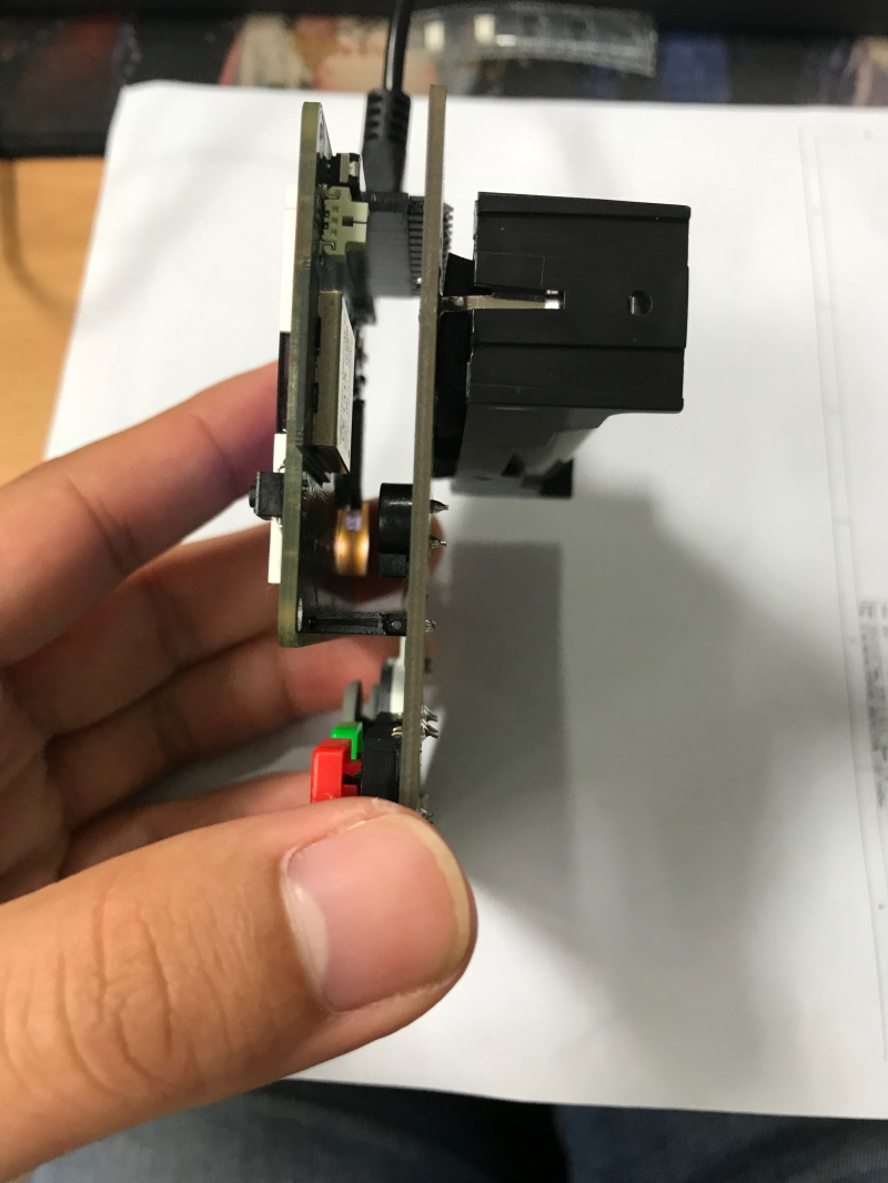
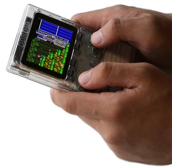
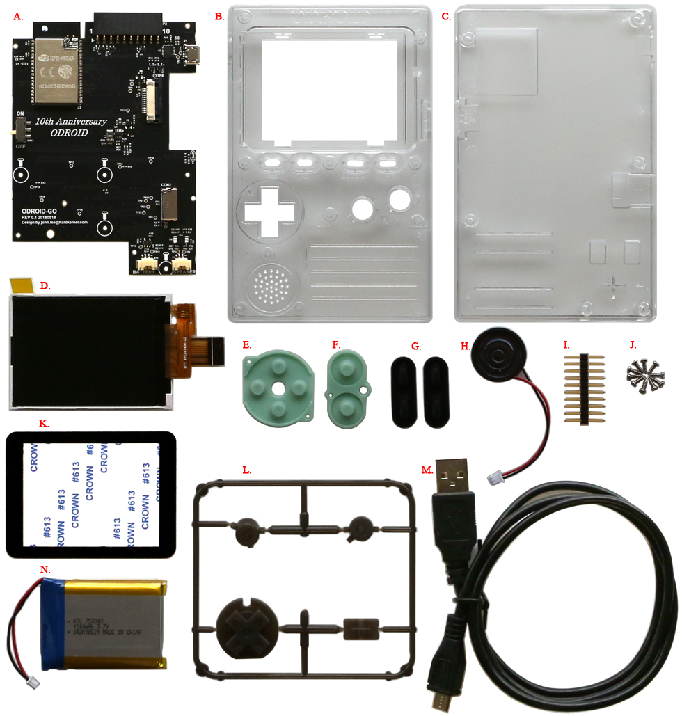
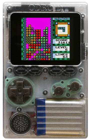
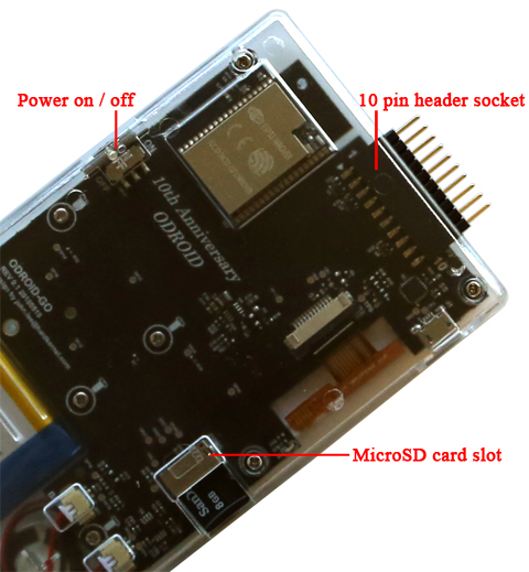
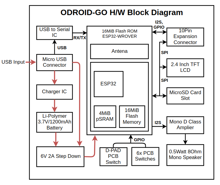
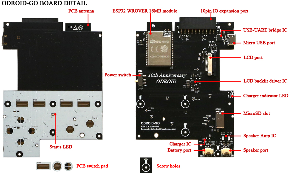

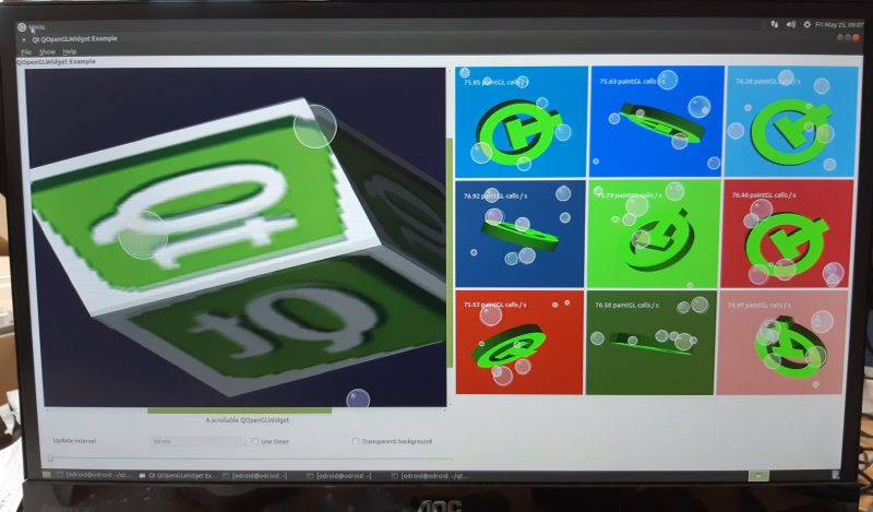
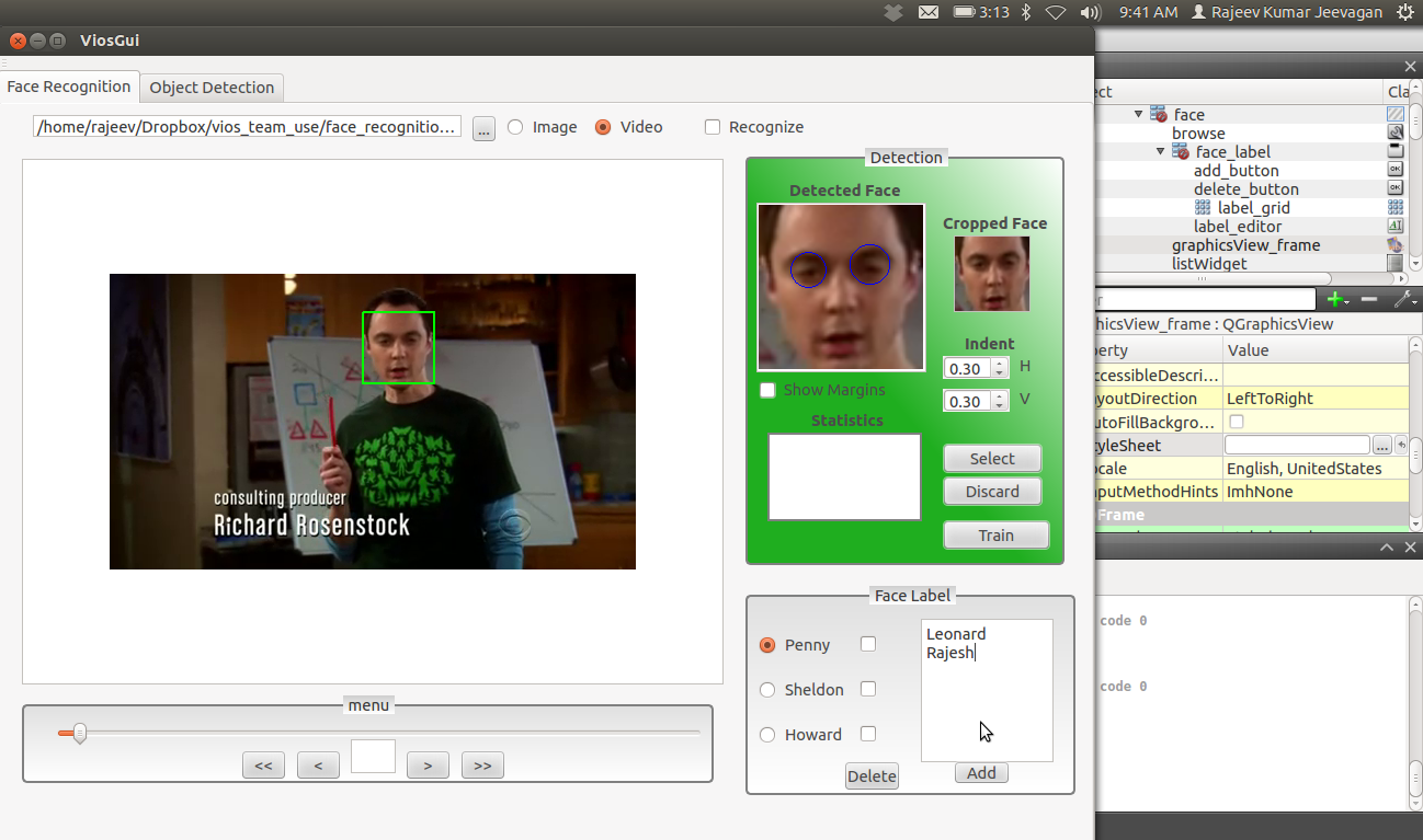

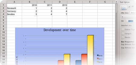
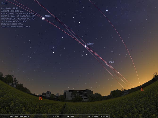

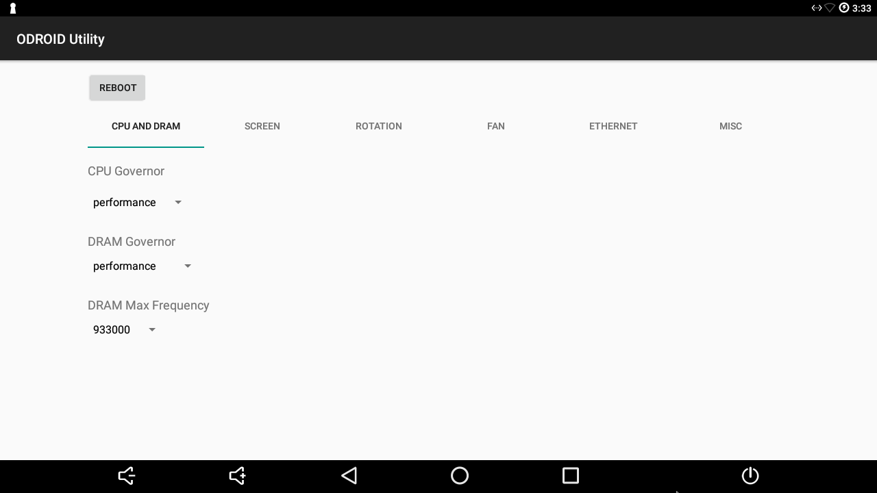
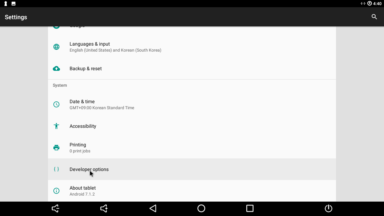
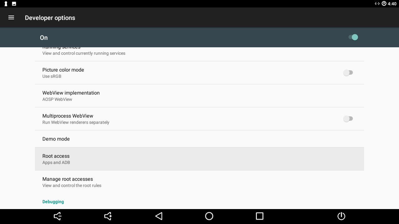
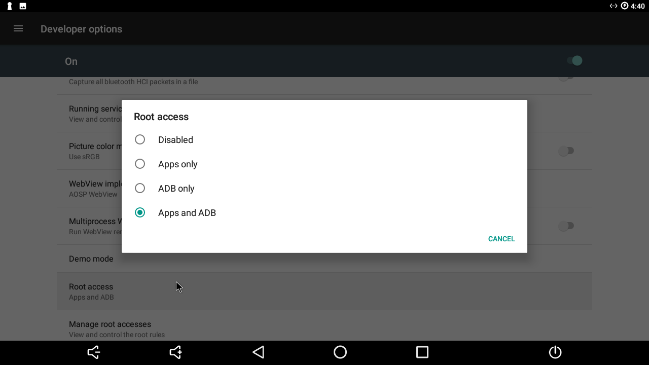
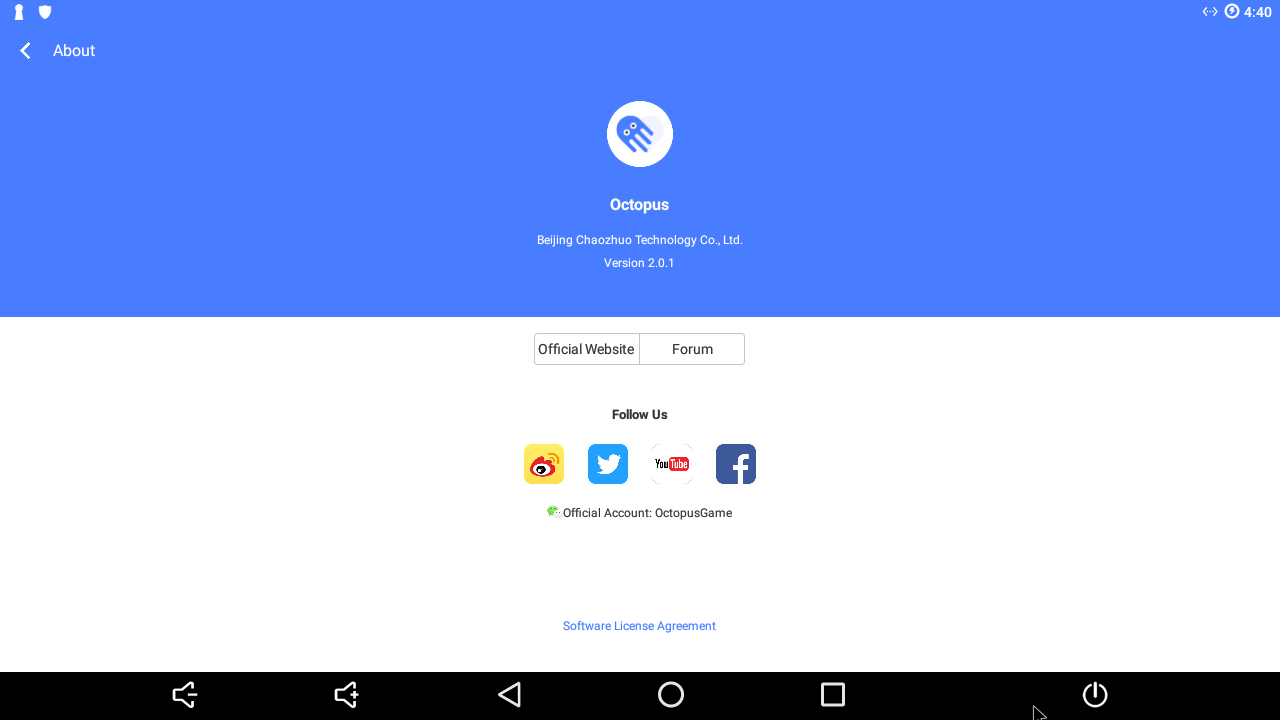
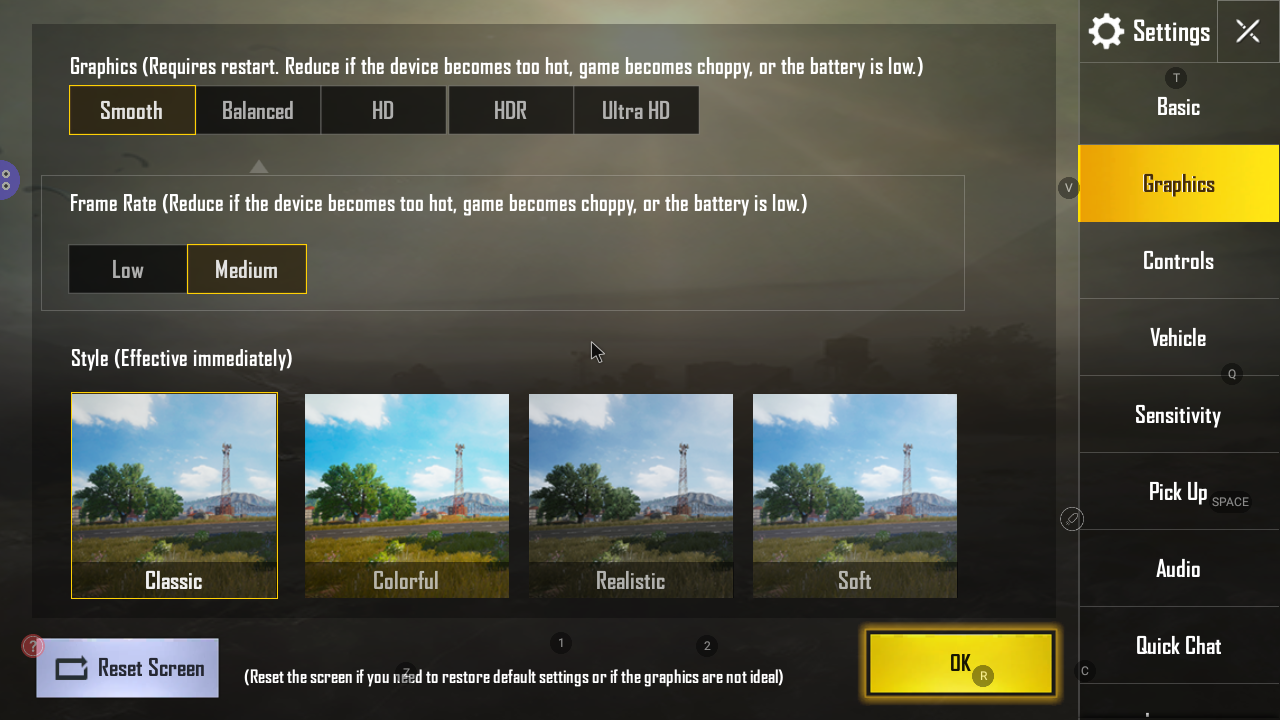
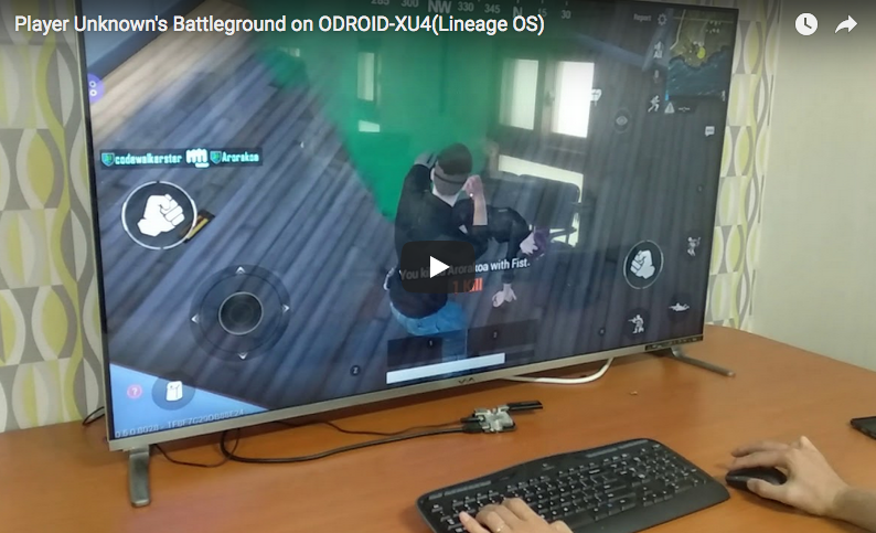
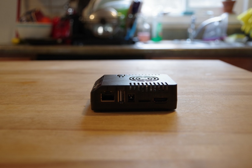 Installing Recalbox on the ODROID-XU4 is fairly simple. You only need the ODROID-XU4 board, a compatible 5V/4A power supply (PSU), eMMC module or microSD card running the ODROID-XU4 Recalbox image, and an optional but recommended case.