Backup Scripts: Keep your data safe for your peace of mind

Backup Scripts

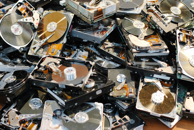
You've worked hard to get your system in shape and worked out all of the bugs, but you know that things are not going to last, and you may be an update away from a broken browser, or you might want to experiment with a new kernel or beta package. To save yourself from future trouble, it's always a good idea to make a backup! However, backups are usually a source of confusion on the forums, and lots of new users struggle with them. In this article, we'll learn what needs to be done to keep your system safe.

Disks, partitions and file systems

Seasoned computer users have no problem distinguishing between disks, partitions and filesystems, but let's analyze them to have a common starting point. A disk is generally a physical device that stores data into randomly-accessible blocks. In more complex setups, multiple physical disks can be combined as RAID arrays using either hardware or software, and exposing them to the operating system as virtual disks. Partitions are sections on disks that usually hold a filesystem. Filesystems manage how files and data are stored in order to be found later on. In order to make a backup of your ODROID system, you will need to preserve the partition information and the contents of the partitions.

Figure 1 - Partition layout of an Odroid C1 triple-boot image
Figure 1 - Partition layout of an ODROID-C1 triple-boot image

All disks start off with a 512 byte block of data that typically holds the bootloader (for x86 systems, 446 bytes) and the 64B Master Boot Record (MBR), which is explained at http://bit.ly/2bMCTUh. The MBR is a table with the start offset, length and partition type of your 4 primary partitions. These are the partitions mapped as 1-4 in the Linux kernel (e.g., sda1-sda4 for a disk called sda). The MBR is an old data structure, introduced in 1983, so it has some limitations. The need to use ever-larger disks (>2TB) led to the introduction of the GUID Partition Table (GPT) which replaces the MBR in newer systems and is detailed at http://bit.ly/2bvb4oL. ODROIDs can use both MBR and GPT, but the boot media is designed as a MBR volume because of its relatively small size and simplicity.

But, as shown in Figure 1, a disk may have more than 4 partitions. This is achieved by using a trick - one primary partition is marked as "extended" and it can contain any number of logical partitions. Linux represents them with numbers from 5 upwards (i.e., sda5, sda6 and so on). The partition information for the logical partitions is stored in structures similar to the MBR called Extended Boot Record (EBR) as explained at http://bit.ly/2bw47Re, which looks like a linked list as shown in Figure 2, but precedes the actual partition on disk.

Figure 2 - EBR position on disk

The partitions you'll usually see on ODROIDs are FAT16/FAT32 (seen as VFAT under the mount command) and Ext2/3/4. There are other partition types supported by Linux, such as NTFS, XFS, and ZFS, but they are usually not critical to the boot process, so they will be out of our scope. There are backup tools such as BackupPC (http://bit.ly/2bx3J6R) or Clonezilla (http://bit.ly/1Iq2mN7), which support more partition types or do backup on file level. These same tools should be used to backup your personal data, such as files, pictures or music. It's also a good idea before starting a backup to do some "spring cleaning" and delete things you no longer need, such as temporary files or downloads, in order to reduce the time it takes to do the backup and the size of the backup file. For instance, you can delete the cache of downloaded apt packages with the following command:

$ sudo apt-get clean

Backup strategies

There are a few ways of making a backup of your eMMC/SD card. The simplest to implement is to make a 1:1 binary copy of your data to an image file. For this task, you can use a tool such as dd or Win32DiskImager. Note that all of the commands that follow expect to have the variable $backupDir replaced by the path to your desired backup directory, which can't be on the same partition you're trying to backup for obvious reasons.

$ sudo dd if=/dev/mmcblk0 of=$backupDir/backup.img bs=1M
In the command above, "if" represents "input file" and should point to the block device representing your disk, such as /dev/mmcblk0, and "of" represents the "output file" where data should be written to. The parameter "bs" represents "block size", which signifies how much data is read and written at once. A variation of the dd command that shows progress uses the "pv" command (pipe viewer):
# apt-get install pv
# dd if=/dev/mmcblk0 bs=1M | pv | dd of=$backupDir/backup.img
Restoring the data is equally easy: just replace the values of "if" and "of":
$ sudo dd if=$backupDir/backup.img of=/dev/mmcblk0 bs=1M
Note that dd makes a binary copy of your disk. This means that it will copy also the free space on your disk. The default output file will be as large as your disk, which means that copying a 64GB SD card of mostly empty space will take a long time and take up a lot of room. The advantage is that you can later run tools like PhotoRec (http://bit.ly/1jwXElB) on the free space and possibly recover deleted files, which is useful when doing data forensics or recovering from bad media. The disadvantage is that the image will be big and slow to copy. You can use dd together with gzip to shrink the image before writing it to reduce size a bit, but you won't save time:
# dd if=/dev/mmcblk0 bs=1M | gzip -c > $backupDir/backup.img.gz
# gunzip -c $backupDir/backup.img.gz | dd of=/dev/mmcblk0 bs=1M
Also note that, in theory, you can do a backup with dd on a live system by copying it while the partitions are mounted, but there is a risk of inconsistencies if files are changed while doing the backup. It's best to do an offline backup by pulling the eMMC/SD card, plug it into a different system, and do the backup without having mounted partitions. There's also a disadvantage when copying between media of slightly different sizes. Since not all 16GB cards are exactly the same size, you might end up with a truncated partition on your destination.

The "dd" utility has the advantage that it is easy to use, but to gain backup/restore speed and minimize necessary backup space, you need to break up the backup operation into several steps and avoid backing up free space. For this, you'll need to backup the MBR + EBR, bootloader, and individual partitions.

You can still cheat and use dd if you use gparted in order to shrink your largest/last partition to only the used size, dd up to that size, then resize the partition back to the original size after you restore it, but it involves some manual work.

MBR backup and restore

The MBR and EBR are small data structures and can be easily backed up with dd. But because the EBR's position on disk can vary, you should rely on a partitioning tool to extract and restore the MBR/EBR data. Such a tool is sfdisk:

$ sudo apt-get install sfdisk
$ sudo sfdisk -d /dev/mmcblk0 > $backupDir/partition_table.txt
To restore it later, you need to supply the saved file to sfdisk like this:
$ sudo sfdisk /dev/mmcblk0 < $backupDir/partition_table.txt
Note that overwriting the MBR on a disk with existing partitions is equivalent to deleting the partitions since the operating system will not be able to find the offsets to the old partitions anymore, so use the restore step with extreme care! This backup can be performed on a live system without risks since partition tables are not usually changed during runtime.

Bootloader backup and restore

ODROIDs use U-Boot as a bootloader, as detailed in the November 2015 issue of ODROID Magazine November 2015 (http://bit.ly/2bA3P9g). U-Boot stores its code and data in the unallocated space after the MBR and at the beginning of the first partition. There is also some bootstrap code in the first 446 bytes in the first sector, before the partition table. Since the size and structure of U-Boot may differ between ODROID models, it's safest to do a binary backup of this unallocated space with dd. First, you need to find out the start sector of the first partition with sfdisk:

$ sudo sfdisk -l /dev/mmcblk0
Figure 3 - Identify the start sector of the first partition with sfdisk and sector size

As indicated in Figure 3, the first partition (loop0p1) starts at offset 49152, so we'll need to copy everything up to and including sector 49151. The bs (block size) parameter must match what sfdisk reported in the "Units" line:

$ sudo dd if=/dev/mmcblk0 of=$backupDir/bootloader.bin bs=512 count=49151
Note that the dd command will also copy over the MBR, which is sector 0). To restore the bootloader and skip restoring the partition table as well, you can use the following command:
$ sudo dd if=$backupDir/bootloader.bin of=/dev/mmcblk0 bs=512 skip=1 seek=1
You should also restore the bootstrap code from the first sector:
$ sudo dd if=$backupDir/bootloader.bin of=/dev/mmcblk0 bs=446 count=1
To restore the partition table as well, do not add the skip and seek parameters. This too can be done on a live system since the data is mostly read-only.

FAT partitions backup and restore

By default, Hardkernel's images come with a FAT16/32 partition mounted under /media/boot that contains the kernel, initrd, device tree and boot.ini files. All of these are crucial to system startup. Android systems expose this partition as "sdcard" storage.

There are several tools for linux that backup FAT partitions. I used to use partimage, but it fails to verify the checksum of the partitions on C2, so I switched to partclone. Partclone can do a block backup of FAT partitions preserving data at the same offsets, but can skip empty space.

$ sudo apt-get install partclone
$ sudo partclone.vfat -c -s /dev/mmcblk0p1 -O $backupDir/partition_1.img
The "-c" specifies "clone", "-s" is the source partition, which is the first partition in our case, and "-O" is the output file, which will get overwritten if it exists. Note that partclone cannot operate on mounted filesystems and will exit with an error. In order to back up from a running ODROID, you will need to unmount /media/boot, perform the backup and mount it back again.

To restore a FAT partition, you can run the following command:

$ sudo partclone.restore -s $backupDir/partition_1.img -o /dev/mmcblk0p1
Figure 4 - Partclone backup with prior unmounting of /media/boot

Unfortunately, PartClone will not allow you to restore a partition to a smaller or larger target partition, so any size adjustment you will need to make after the restore is done. You can actually restore to a larger partition, but you will need to manually grow it in order to use the extra space.

Ext2/3/4 partitions backup and restore

In order to backup and restore Ext2/3/4 filesystems, we'll need to use a different tool called FSArchiver. Unlike PartClone, FSArchiver creates a file level backup and reconstructs the filesystem upon restore. Unfortunately, because of certain particularities of FAT systems where Windows boot files need to be at specific offsets, the author of fsarchiver does not support backing up FAT filesystems as well, so we're stuck to using two tools for the job. But with the help of external packages fsarchiver can support other filesystems as well, such as XFS, ReiserFS, JFS, BTRFS and NTFS. It usually backs up unmounted filesystems, but can be used on live filesystems as well with the "-A" flag, which may not always work. FSArchiver has the advantage that it can restore a filesystem in a bigger or smaller target partition while preserving UUIDs. In order to back up the second partition, you can run the following commands:

$ sudo apt-get install fsarchiver
$ sudo fsarchiver -o -v -A -j 4 savefs $backupDir/partition_2.fsa /dev/mmcblk0p2
The "-o" flag means overwrite the destination file if it exists, "-v" is verbose output, "-A" allows you to backup a mounted partition and "-j 4" allows it to use 4 cores for compression.

In order to restore a fsa backup you can run the following command:

$ sudo fsarchiver restfs $backupDir/partition_2.fsa id=0,dest=/dev/mmcblk0p2
Note that since FSArchiver supports multiple partitions inside an archive, it needs you to specify which partition id to restore. In our example, we store only one partition in an archive, so you'll always specify id=0 when restoring.

SPI Flash

Newer boards, like the development Odroid N1 may feature a low capacity SPI NAND Flash chip designed to store the bootloader and kernel, so that it can boot from network, or from a SATA disk, without the need of a eMMC or SD card. Even if the layout of this chip hasn't been decided fully at the time of this writing, we can still back it up and restore it as a block device with dd. You can get a list (and description) of MTD devices in your Odroid by running:

$ sudo cat /proc/mtd
 dev: size erasesize name
 mtd0: 01000000 00001000 "spi32766.0"
To back it up, you can simply use:
$ sudo dd if=/dev/mtd0 of=$backupDir/flash_mtd0.bin bs=4096
In order to write to a flash device, to restore it, you need to erase the block you're going to write to. Fortunately, since we will write the whole device, we can erase it all before writing. For this we need mtd-utils which provides flash_erase:
$ sudo apt-get install mtd-utils
$ sudo flash_erase -q /dev/mtd0 0 0
$ sudo dd if=$backupDir/flash_mtd0.bin of=/dev/mtd0 bs=4096

ODROID backup tool

Now that you know how to do things manually, you may question why backup and restore operations are not simpler, using point and click operations. I agree that nobody has the time to remember all the command line arguments from various commands, so I hacked together a rudimentary GUI that can walk you through your backup and restore process.

The tool is descriptively called "odroid-backup". It's written in Perl and uses zenity and dialog to build a rudimentary GUI, because I'm too old to learn Python. To install the tool, you can download it from my GitHub repository:

$ sudo wget -O /usr/local/bin/odroid-backup.pl https://raw.githubusercontent.com/mad-ady/odroid-backup/master/odroid-backup.pl
$ sudo chmod a+x /usr/local/bin/odroid-backup.pl
The script depends on a bunch of non-standard Perl modules as well as some Linux utilities, and will display a list of missing dependencies and ways of fixing it when you first run it. To install all dependencies at once, run the following:
$ sudo apt-get install libui-dialog-perl zenity dialog libnumber-bytes-human-perl libjson-perl sfdisk fsarchiver udev util-linux coreutils partclone parted mtd-utils
The script is designed to run on Linux systems, such as a PC to which you've hooked up a SD card or eMMC module via a USB adapter, or directly on the ODROID (sorry Windows fans). Also, the script will create graphical windows if it detects that you're running an X11 session, or will fall back to ncurses (display) if you're connected via ssh or terminal. You can manually force this with the --text switch.

Figure 5 - Zenity vs display rendering

To perform a backup, start the tool in a terminal and select "Backup partitions", then select OK (1):

$ sudo odroid-backup.pl
You will be presented with a list of removable drives in your system. You can start the program with the -a flag in order to display all drives, which is the case when running directly on the ODROID, since eMMC and SD are shown as non-removable. Select the desired one and click OK (2). You will then be presented with a list of partitions on that drive. Select the ones you wish to backup (3). Next, you will have to select a directory to which to save the backups. It's best to have a clean directory (4). Press OK, and backup will start with a rudimentary progress bar to keep you company (5). When the backup is done, you will be presented with a status window with the backup results and possible errors (6). The backup files have the same naming convention used in this article. To backup a Flash NAND as well you need to re-run the tool and select it from the available disks. You can save the resulting file in the same directory as the partition backups.

Figure 6 - Backup steps

To perform a restore, start the tool in a terminal, select "Restore partitions", then select OK (1):

$ sudo odroid-backup.pl
You will have to select the directory holding your valuable backups and select OK (2). In the resulting window, select which partitions you wish to restore from the backup and select OK (3). Note that the partitions are restored in the same order as they were on the original disk, which means that partition 1 will be the first partition, and so on. In the last window, you will be asked on which drive to restore the data (4). Enjoy watching the progress bar progressing (5), and in the end you will have a status window with the restore results (6). The log file is also saved in /var/log/odroid-backup.log.

Figure 7 - Restore steps

Known limitations

If you backup an eMMC for XU3/4, the hidden sectors (/dev/mmcblk0boot0, /dev/mmcblk0boot1) are not backed-up/restored. These blocks contain parts of the UBoot loader. When restoring a backup on an SD card or on a new eMMC, the board might boot with an older UBoot version (stored before the first partition). As a result of this the UBoot environment might be incomplete (e.g. there is no ${board_name} set), and booting might be different than normal (network might be missing). Once you do boot it is recommended that you reinstall uboot with this command on the new card:

$ sudo apt-get install --reinstall uboot
As you might suspect, no piece of software is free of bugs, but hopefully this six step script will have its uses. This script has some shortcomings, such as the zenity windows not always displaying the instruction text, which is why I added the title bar. There is also no validation of the backups or restores. You will have to review the log to verify that the backup or restore operation completed successfully. One other limitation is that FAT partitions need to be manually unmounted before backup, although Ext2/3/4 can be backed-up live. Finally, the sfdisk utility on Ubuntu 14.04 doesn't support JSON output, so it will not work there, although I can add support if needed. The program was tested by backing up and restoring several official Hardkernel Linux and Android images, as well as triple-boot images, and so far everything seems to work. Ideas for improvement and patches are welcome as always on the support thread at http://bit.ly/2bEyFzl.

Android Auto: Take Your ODROID On The Road

Android Auto

Android Auto is a Google application that allows an ODROID-C2/C1+ to function as an in-dash car computer to support navigation, audio, and hands-free operation. Video instructions are available on the YouTube video, "[ODROID/Android Auto]chip car head unit". The application runs inside Linux using the OpenAuto application.

Figure 1
Figure 1

Figure 2
Figure 2

Materials

Figure 3 - We prepared two buttons for use as a shut-down switch. For this project, we used the bigger button

Figure 4 - We prepared two buttons for use as a shut-down switch. For this project, we used the bigger button

Figure 5 - We used a cigarette lighter power adapter as power supply

Figure 6 - To connect the power adapter to SmartPower2, we changed the connector to a 5.5mm L type cable

Software

This project is based on ubuntu64-16.04.3-mate, version 2.2. Android Auto works well on both the ODROID-C2 and the ODROID-C1+.

Install dependencies

Before installing the Audio Auto, you should install the dependency packages.

$ sudo apt-get update && sudo apt-get upgrade
$ sudo apt-get install -y git-core curl dh-autoreconf libboost-all-dev libusb-1.0.0-dev libssl-dev cmake libqt5multimedia5 libqt5multimedia5-plugins libqt5multimediawidgets5 qtmultimedia5-dev libqt5bluetooth5 libqt5bluetooth5-bin qtconnectivity5-dev pulseaudio gstreamer1.0-plugins-bad gst123 librtaudio-dev
The following script will automatically log into the Android account after each boot:
$ sudo vi /usr/share/lightdm/lightdm.conf.d/60-lightdm-gtk-greeter.conf
 [Seat:*]
 greeter-session=lightdm-gtk-greeter
 autologin-user=odroid

Installation

To use Android Auto, you will need to install OpenAuto, which requires both aasdk and protocol-buffers to be installed. Before updating the compiler, please check the version of the GCC compiler. The GCC version should be 6 or higher:

$ gcc -v
 Using built-in specs.
 COLLECT_GCC=gcc
 COLLECT_LTO_WRAPPER=/usr/lib/gcc/aarch64-linux-gnu/5/lto-wrapper
 Target: aarch64-linux-gnu
 Configured with: ../src/configure -v --with-pkgversion='Ubuntu/Linaro 5.4.0-6ubuntu1~16.04.9' --with-bugurl=file:///usr/share/doc/gcc-5/README.Bugs --enable-languages=c,ada,c++,java,go,d,fortran,objc,obj-c++ --prefix=/usr --program-suffix=-5 --enable-shared --enable-linker-build-id --libexecdir=/usr/lib --without-included-gettext --enable-threads=posix --libdir=/usr/lib --enable-nls --with-sysroot=/ --enable-clocale=gnu --enable-libstdcxx-debug --enable-libstdcxx-time=yes --with-default-libstdcxx-abi=new --enable-gnu-unique-object --disable-libquadmath --enable-plugin --with-system-zlib --disable-browser-plugin --enable-java-awt=gtk --enable-gtk-cairo --with-java-home=/usr/lib/jvm/java-1.5.0-gcj-5-arm64/jre --enable-java-home --with-jvm-root-dir=/usr/lib/jvm/java-1.5.0-gcj-5-arm64 --with-jvm-jar-dir=/usr/lib/jvm-exports/java-1.5.0-gcj-5-arm64 --with-arch-directory=aarch64 --with-ecj-jar=/usr/share/java/eclipse-ecj.jar --enable-multiarch --enable-fix-cortex-a53-843419 --disable-werror --enable-checking=release --build=aarch64-linux-gnu --host=aarch64-linux-gnu --target=aarch64-linux-gnu
 Thread model: posix
 gcc version 5.4.0 20160609 (Ubuntu/Linaro 5.4.0-6ubuntu1~16.04.9)
Add the repository via add-apt-repository commands, then install gcc-6:
$ sudo apt update
$ sudo add-apt-repository ppa:ubuntu-toolchain-r/test -y
$ sudo apt update
$ sudo apt install gcc-snapshot -y
$ sudo apt update
$ sudo apt install gcc-6 g++-6 -y
$ sudo update-alternatives --install /usr/bin/gcc gcc /usr/bin/gcc-6 60 --slave /usr/bin/g++ g++ /usr/bin/g++-6
$ sudo update-alternatives --config gcc
After installation, you should see that the updated GCC is available:
$ gcc -v
 Using built-in specs.
 COLLECT_GCC=gcc
 COLLECT_LTO_WRAPPER=/usr/lib/gcc/arm-linux-gnueabihf/6/lto-wrapper
 Target: arm-linux-gnueabihf
 Configured with: ../src/configure -v --with-pkgversion='Ubuntu/Linaro 6.3.0-18ub
 untu2~16.04' --with-bugurl=file:///usr/share/doc/gcc-6/README.Bugs --enable-languages=c,ada,c++,java,go,d,fortran,objc,obj-c++ --prefix=/usr --program-suffix=-6
 --program-prefix=arm-linux-gnueabihf- --enable-shared --enable-linker-build-id
 --libexecdir=/usr/lib --without-included-gettext --enable-threads=posix --libdir=/usr/lib --enable-nls --with-sysroot=/ --enable-clocale=gnu --enable-libstdcxx-debug --enable-libstdcxx-time=yes --with-default-libstdcxx-abi=new --enable-gnu-unique-object --disable-libitm --disable-libquadmath --enable-plugin --with-system-zlib --disable-browser-plugin --enable-java-awt=gtk --enable-gtk-cairo --with-java-home=/usr/lib/jvm/java-1.5.0-gcj-6-armhf/jre --enable-java-home --with-jvm-root-dir=/usr/lib/jvm/java-1.5.0-gcj-6-armhf --with-jvm-jar-dir=/usr/lib/jvm-exports/java-1.5.0-gcj-6-armhf --with-arch-directory=arm --with-ecj-jar=/usr/share/java/eclipse-ecj.jar --with-target-system-zlib --enable-objc-gc=auto --enable-multiarch --enable-multilib --disable-sjlj-exceptions --with-arch=armv7-a --with-fpu=vfpv3-d16 --with-float=hard --with-mode=thumb --disable-werror --enable-multilib --enable-checking=release --build=arm-linux-gnueabihf --host=arm-linux-gnueabihf --target=arm-linux-gnueabihf
 Thread model: posix
 gcc version 6.3.0 20170519 (Ubuntu/Linaro 6.3.0-18ubuntu2~16.04)
Next, download the protobuf-compiler source code:
$ wget https://github.com/google/protobuf/archive/v3.0.0.zip
$ unzip v3.0.0.zip
$ cd protobuf-3.0.0
In the autogen.sh file, change the Google Mock packages to Google Test packages:
$ vi autogen.sh
 .
 .
 . (:32)
 if test ! -e gmock; then
 curl $curlopts -L -O https://github.com/google/googletest/archive/release-1.7.0.zip
 unzip -q release-1.7.0.zip
 rm release-1.7.0.zip
 mkdir -p gmock/gtest
 mv googletest-release-1.7.0 gmock/gtest
 fi
 .
 .
 .
If you are using an ODROID-C2 for your build, you can add the “-j4” option to the “make” command but on the ODROID-C1+, you should avoid this option due to the lower system memory size.
$ ./autogen.sh
$ ./configure --prefix=/usr/lib/arm-linux-gnueabihf/
$ make [-j4]
$ sudo make install
$ sudo ldconfig
$ export PATH=/usr/lib/arm-linux-gnueabihf/bin/:$PATH
$ cd
$ git clone -b master https://github.com/f1xpl/aasdk.git
$ mkdir aasdk_build
$ cd aasdk_build
$ cmake -DCMAKE_BUILD_TYPE=Release ../aasdk
$ make [-j4]
Finally, build and install Open Auto:
$ cd
$ git clone -b master https://github.com/f1xpl/openauto.git
$ mkdir openauto_build
$ cd openauto_build
$ cmake -DCMAKE_BUILD_TYPE=Release -DRPI3_BUILD=FALSE -DAASDK_INCLUDE_DIRS="/home/odroid/aasdk/include" -DAASDK_LIBRARIES="/home/odroid/aasdk/lib/libaasdk.so" -DAASDK_PROTO_INCLUDE_DIRS="/home/odroid/aasdk_build" -DAASDK_PROTO_LIBRARIES="/home/odroid/aasdk/lib/libaasdk_proto.so" ../openauto
$ make [-j4]
$ echo "./openauto/bin/autoapp &" >> .bashrc

Add account to group

To solve the account permission problem, set the user group as shown below:

$ sudo usermod -a -G root odroid
$ sudo usermod -a -G tty odroid
$ sudo usermod -a -G voice odroid
$ sudo usermod -a -G input odroid
$ sudo usermod -a -G audio odroid
$ sudo usermod -a -G pulse odroid
$ sudo usermod -a -G pulse-access odroid
You should see the Android auto ready screen upon booting.

Figure 7
Figure 7

Figure 8
Figure 8

Attaching and setting the materials

To use the ODROID-VU7 display, edit the boot.ini files as shown below. You should edit resolution and vout_mode options. The ODROID-VU7 has 800×480 60hz, and DVI mode.

$ sudo vi /media/boot/boot.ini

# setenv m "576p" # 720x576
setenv m "800x480p60hz" # 800x480
# setenv m "800x600p60hz" # 800x600
# setenv m "1024x600p60hz" # 1024x600
# setenv m "1024x768p60hz" # 1024x768
# setenv m "1360x768p60hz" # 1360x768
# setenv m "1440x900p60hz" # 1440x900
# setenv m "1600x900p60hz" # 1600x900
# setenv m "1680x1050p60hz" # 1680x1050
# setenv m "720p" # 720p 1280x720
# setenv m "800p" # 1280x800
# setenv m "sxga" # 1280x1024
# setenv m "1080i50hz" # 1080I@50Hz
# setenv m "1080p24hz" # 1080P@24Hz
# setenv m "1080p50hz" # 1080P@50Hz
# setenv m "1080p" # 1080P@60Hz
# setenv m "1920x1200" # 1920x1200

# HDMI DVI Mode Configuration
# setenv vout_mode "hdmi"
setenv vout_mode "dvi"
# setenv vout_mode "vga"
Figure 9
Figure 9

Mount SmartPower2

This is an optional device, and you can use any other 5V/3A PSU for this. The SmartPower2 has an auto-run function, and you can communicate with it via WiFi.

Figure 10 - Output power ON/OFF automatically when you power on the SmartPower2

Check the Auto Run option and connect SmartPower2 using the cigarette lighter power adapter as the input and the ODROID-C1+ as the output.

Figure 11
Figure 11

Figure 12
Figure 12

Mount Stereo Boom Bonnet

If you have to load the driver every time your ODROID-C1+/C2 starts up, simply register the driver into /etc/modules (more details):

odroid@odroid64:~$ su
 Password: /* root password is "odroid" */
 root@odroid64:/home/odroid# echo "snd-soc-pcm5102" >> /etc/modules
 root@odroid64:/home/odroid# echo "snd-soc-odroid-dac" >> /etc/modules
 root@odroid64:/home/odroid# exit
 exit
 odroid@odroid64:~$
Select “output to ODROID-DAC Analog stereo” via System » Preferences » Hardware » Sound » Output.

Figure 13 - Select Output: ODROID-DAC Analog Stereo

Figure 14 - Make sure to check the connector!

Set Up your power button

Using the keypads on the TFT LCD, the Android Auto system can be shut down by powering off the car system, but we wanted to include a separate power button for convenience. To make this work, change “KEY_UP” to “KEY_POWER” in the source code for the tftlcd_key service:

{ PORT_KEY1, HIGH, KEY_UP, KEY_RELEASE },
Next, update rc.local to automatically load the tftlcd_key service on boot:
$ sudo vi /etc/rc.local

# By default this script does nothing.
 sudo /home/odroid/tftlcd_key &

if [ -f /aafirstboot ]; then /aafirstboot start ; fi
Now connect the power button to the GPIO expansion connectors J2. We used Pin 6 and Pin 12.

Figure 15
Figure 15

Figure 16
Figure 16

To map a shutdown action, go to System » Preferences » Hardware » Power Management » General.

Figure 17 - When power button is pressed: Shutdown

Figure 18
Figure 18

Mount USB Microphones

To use Google Assistant, you will also need a USB microphone. Set the input to USB device using System » Preferences » Hardware » Sound » Input.

Figure 19
Figure 19

Figure 20 - Select input : USB PnP Sound Device Analog Mono

Figure 21
Figure 21

Install Android Auto in a car

We’ve now installed the Android Auto device in my personal car, which works great. After start up, Android Auto is automatically ready to connect your Android device. After connecting your Android device to Android Auto, the Android Auto will detect your device so that you can use it.

Figure 22
Figure 22

Figure 23
Figure 23

Figure 24
Figure 24

ODROID-C2 Kodi Media Center: Build Your Own Entertainment System With A Custom LED-enabled Case

I am one that likes my movies, and also one that likes to fiddle and make, so the two came together in wanting an easy way to play things from my movie/music collection. It had to be simple to use, reliable and look good too. My movie / music collection is stored on a NAS drive allowing me to store the originals out of the way. So, I thought it was going to be simple given that all I wanted to do was play Blu-Ray iso’s, DVD VideoTS/VOBs, CD MP3s and FLAC files.

Over the years, I have tried many media clients on various platforms, but they were often tripped up by poor audio and unreliable video playback. It did not seem to be related to cost as I have spent a fair bit on dedicated media-center PCs over the years. I have even purchased ready-made solutions. One thing that did keep happening though, was that I kept coming back to Kodi, previously known as XBMC.

Then came along the Raspberry Pi, which was full of promise, attractively priced, with lots of dedicated programming from the Kodi community. For the money, it is incredible what can be done. However, I found everyday use sluggish and even with my basic video standards with many would cause it to skip and stutter.

Kodi installation

Anyone who has used Kodi will know that it comes in a huge number of flavors supporting a huge range of hardware. After the support issues of keeping the OS alive with Windows I knew this had to be moved out of the picture and came across a build called LibreELEC that supplied a basic Linux OS leaving all the power of the device to be dedicated to the main purpose of running Kodi. After a bit of research and LibreELEC’s supported platforms, I came across Hardkernel’s ODROID-C2, which is like a Raspberry Pi in terms of size and cost. With it, I had a slick Kodi platform up and running in minutes and it just worked! So much so it sat as just a bare board on top of my set-top box in my lounge for ages. I almost forgot about it, sitting back playing movies. Installation is simple:

A note on the reader: I am not sure if this has been fixed, but I found that using Rev0.2 20130402 of the reader tricky and it only seemed to work with certain slots or SD adaptors. I think it is down to the mechanical tolerances of the PCB.

Finding a home for the ODROID-C2

Along came a nice shiny 4K OLED TV, and I took stock of my supporting hardware thinking it was really about time to find the ODROID-C2 a proper home/housing. With most of the purpose build units wrapping the PCB you end you with cables coming at the box from all angles and I wanted it to be more like a set top box. A quick search came up with a nice Aluminium chassis from DoukAudio available all over eBay.

Figure 1 - DoukAudio Chassis

However, I still had to get all the connections I needed to the back of the chassis including, power, LAN, USB and HDMI. Again, a search on eBay resulted in a viable short HDMI adapter.

Figure 2 – HDMI Adapter

PSU

From my involvement with RPi’s I knew a good PSU was also important, so I built my own basic internal 5V 2A supply that was hardwired directly to J8 of the C2 PCB and followed the advice to remove jumper J1 disabling the USB OTG input.

You could of course purchase a ready built module if you do not feel confident with mains or just power via the normal way using the micro USB port or DC jack.

Heatsink

Given that I had a nice large Aluminium case it seemed sensible to heatsink the C2 via the housing rather than drilling holes all over it and/or using forced air. I removed the stock heatsink and used a block of aluminium to take the heat of the processor out to the case.

Figure 3 – Heatsink
Figure 3 – Heatsink

Overclocking

With a nice cool processor, I had some headroom for overclocking. A good power supply is a must. I suggest overclocking one step at a time. First, I followed the overclocking steps in the forum article: (https://forum.odroid.com/viewtopic.php?t=30078&p=214852). For me it was a case of loading up the eMMC card on a PC and editing the boot.ini file to see what worked. A CPU frequency of 1.752GHz was stable for me. This was the line I added to the boot.ini file:

 setenv max_freq “1752”
If there are any other lines starting with setenv max_freq simply comment them out using a “#” in front eg: #setenv max_freq “1536”. Plug the card back in to the C2, reboot and test. Next, was setting up the 792 Mhz graphics chip overclock (https://goo.gl/TgGqVx). For this you need to login to your box while it is booted. First you need to know its IP address and this can be found on the Kodi Settings/System information/Network page. Then using a telnet client such as PuTTy (https://www.chiark.greenend.org.uk/~sgtatham/putty), SSH into your box and logon as root using the password libreelec. At the command line run the following, then reboot:
 $ echo "echo 5 > /sys/class/mpgpu/cur_freq" >> /storage/.config/autostart.sh
The final overclock you can apply is to the RAM (http://odroid.com/dokuwiki/doku.php?id=en:c2_adjust_ddrclk). Again, SSH into your box and enter the following:
 $ wget https://dn.odroid.com/S905/BootLoader/ODROID-C2/c2_update_ddrclk.sh
 $ chmod +x ./c2_update_ddrclk.sh
 $ ./c2_update_ddrclk.sh 1104
 $ reboot
Please note that overclocking is a trial and error process and not all systems will work the same due to factors such as component tolerances, but give it a go. I was able to overclock the RAM, graphics and processor and still maintain a reliable Kodi box albeit just that much slicker to use and navigate, which was a nice freebie.

Remote Control

A disadvantage of housing the C2 in this way was that the IR remote did not work with the lid on and this was needed to power the board ON/OFF. There are some options to attach an IR receiver via the GPIO pins, but it was a simple task to remove the IR receiver and extend it, so it sat behind one if the existing 3mm LED holes on the chassis front plate. I enlarged this hole to 5mm. Other navigation and control was made super responsive by using the USB Bluetooth adapter (https://goo.gl/zYPdkc), which sat on the rear panel of housing.

Figure 4 - ODROID-C2 Wiring

Front Panel Power LED

One thing was left: I wanted an LED on the front panel to tell when the box was alive. Now the C2 already has some Red & Blue LEDs mounted on the PCB. But the Red LED is connected to the 5V rail and is on all the time the board has power even if the OS has gone to sleep. The Blue heartbeat LED flashes and flickers with activity and can be distracting so much so that this has been turned off with more recent builds of LibreELEC.

I needed another way and the obvious route was the GPIO (https://goo.gl/GzKcVY) pins. Now, I am no programmer and I had already given myself the mental block that it was going to be to hard to implement and put out a request for help on the forum (https://forum.odroid.com/viewtopic.php?f=144&t=30505). In the meantime, I did some digging and it turns out that access to the pins has been made really easy (https://wiki.odroid.com/odroid-c2/application_note/gpio/enhancement_40pins) by Hardkernel.

The LED is 3mm, which is a nice press fit into one of the pre-drilled holes of the front panel. Being a high efficiency White LED, it does not take much current to make it light up and I did not want a flood light illuminating the room. So, I chose a high value current limiting resistor of 47k ohms wired in series with the LED. There is a 3.3V @ 3mA limit on the pin. I could have used Ohm’s law to work out the value, but I just used trial and error to get a brightness that I liked.

I then connected it between 0V & GPIO pin 249 (Pins 7 & 9) of the J2 Header. You can use pins of your choice I just used these because they were next to each other and I could use a pre-wired connector I had.

Figure 5 – ODROID-C2 & LED

With some simple additions to the startup and shutdown scripts, I now have my LED. I edited the files by SSH’ing in and first edited the autostart.sh file:

 $ nano /storage/.config/autostart.sh
I then added the following lines:
 $ echo 249 > /sys/class/gpio/export
 $ echo out > /sys/class/gpio/gpio249/direction
 $ echo 1 > /sys/class/gpio/gpio249/value
For the shutdown procedure, I edited the shutdown.sh file:
 $ nano /storage/.config/shutdown.sh
I then added then following lines:
 $ echo 0 > /sys/class/gpio/gpio249/value
I am not sure if this is the best way, but it works for me. Coupled with a Logitech Elite remote to manage my AV system I now have a family friendly media center.

Figure 6 - Chassis Front

Figure 7 - Chassis Rear

Figure 8 - Chassis Internals

For comments, questions, and suggestions, please visit the original forum post at https://forum.odroid.com/viewtopic.php?f=144&t=30505.

Home NAS and Media Player: Building The Perfect Entertainment System

If you are old enough, you may remember and even relate. Picture this: Early 2000s; DivX--and later, its rival XviD--on the software side, and Pentium 4 and Athlons on the hardware side have finally made video compression a thing; no more bulky, moldy VHS tapes; Napster in its best days, changing P2P history forever. Down here in South America, dial-up internet was finally dying and ADSL had arrived. CD-RW drives were relatively accessible as were their media, especially when compared with the emerging--and expensive--DVD. Youtube wasn’t even born. Add it together and you have the perfect scenario to end up with this in your house:

Figure 1
Figure 1

A CD tower full of physical media containing software, mp3 files, and movies. My tower was exactly like the one pictured, but in tobacco. It could hold up to two hundred CDs. When this was taken, I’d switched from standard CD cases to slim cases, doubling the capacity.

Let’s fast forward a few years to the early 2010s. Youtube existed, but wasn’t as huge as it is today. Netflix had just arrived in South America, with just a few unknown titles in its portfolio. Faster ADSL--2 to 5 mbps--was widely available in most big cities down here. Downloading not just movies, but entire series, became a big deal. Although DVDs and DVD drives had become cheaper, it still wasn’t cheaper than the price per Mb for hard disk drives (HDDs) before the floods in Indonesia (https://goo.gl/rP6kyE). Instead of managing a lot of media, some of which were starting to go bad, why not have it all on HDDs, available with just a click? What about all the CD and DVD covers? Would I trust my family photos to a mechanical HDD prone to failure?

When I started planning how to organize all the media, some research showed XBMC (which would be renamed Kodi a few years later) to be the perfect the solution. XBMC could handle the media library, download covers and lyrics, play back almost any video codec with subtitles, display my family photos, and much more. All it would take was a good amount of work on standardizing folders and file names.

What about the data itself? Disks fail and have bad blocks all the time. RAID is okay, but it had one main problem when dealing with large amount of almost static files--efficiency! RAID 1 would have doubled the cost of disks, space, noise, and energy. RAID 5 seemed okay, but what if a disk failed and I could not get another the same size right away? What if two disks failed? There’s RAID 6 but few controllers support it. What if the controller fails? Different manufacturers have different implementations, making recovery of all the data a nightmare!

Here comes Snapshot RAID. Compared to the usual RAID, it doesn’t work on the disk level. Instead, it works on the data level, over any file system. As long as you have a parity disk with an equal or greater amount of space than the data on the biggest disk on the array, you’re fine. You can even use disks of different sizes. The con is the lack of speed and data availability. Some RAID 5 controllers have live data reconstitution as long as there is just one disk fail. RAID parity is calculated live as data changes. It’s fine, but it does keep all disks spinning most of the time even if you’re just changing a small file. Snapshot RAID, as the name says, works by calculating parity in snapshots. If a disk fails, you’d be stuck with the last snapshot. The good part is that any file that is not in the failed disk is available for use, with no need of reconstruction.

Another goal was merging all data and displaying it as one big disk--almost like JBOD, but with security. Using multiple disks is fine, but makes handling the media too complex. With this in mind, and with plans to use the server as a gaming PC as well (which kind of limited the OS options to Windows) I decided to go with FlexRAID (http://www.flexraid.com/). It was still in its beta stage back then, but showed a lot of potential. To my surprise, as the Brazilian translator I was gifted a full license when it became paid.

With all the software needs addressed, it was time to get my hands dirty and build some hardware. As this was intended to be a media/gaming PC, and as one or two 1.5TB HDDs would be enough to hold all of my media at the time, I chose this case by Sentey to be my living room rack. I will explain all the dust later.

Figure 2
Figure 2

The case could fit up to three 3.5” HDDs, a DVD-RW drive, a micro ATX motherboard, a full ATX PSU and a full height GPU. It worked wonderfully until I added the third disk. No matter how many fans I added, or how fast the fans worked (producing a lot of noise), it would overheat.

It became quite obvious that I would need more fans and additional case to fit more disks as the library grew fast as a result of the convenience of running a 24-hour server and faster available internet.

It just happened that I had this old Compaq desktop case laying around:

Figure 3
Figure 3

With a “few”, not particularly pretty mods in the case and the PSU housing, it became this:

Figure 4
Figure 4

I added seven HDDs and two additional HDD controllers, as the motherboard could only handle two disks. At the time the GPU, the additional fan in the back, and the 120mm one in the top of the case were not yet added. This was the original motherboard, which I replaced a few months later with one that would work better with the processor. The four 80mm fans in the front--added to cool down the HDDs--were removed for cleaning. The power connector is hanging in the front.

Specifications:

  • Motherboard - Abit VA-10 (changed after)
  • Processor - AMD Athlon XP 2000 + (changed to a Atlhon X2 after)
  • RAM - 2Gb DDR 333 (actually, DDR 400 underclocked) (two more gigs added after)
  • SiI 3112 RAID Controller
  • Sil 3114 RAID Controller

HDDs: (the small ones changed to bigger ones after)

  • 1x40Gb IDE (System)
  • 3x1.5Tb SATA (Media)
  • 1x1.5Tb SATA (Personal Data)
  • 1x500Gb SATA (Downloads and virtual memory)
  • 1x1.5Tb SATA (Parity)

Software:

  • Windows 7 32 bits
  • Flexraid
  • XBMC

This setup worked decently for weeks until my then-fiancée (now my wife) started complaining about the noise. I must admit, it was LOUD, especially with the extra fans that came with the graphics card. With a pending marriage and no plans on leaving my fiancée, I decided to expand the bathroom renovation we were planning to the living and bedrooms too. Remember all the dust in first case pic? This is why:

Figure 5
Figure 5

Figure 6
Figure 6

Figure 7
Figure 7

Figure 8
Figure 8

Yes, we use masonry down here in Brazil, not drywall. And yes, renovating an apartment while living in it can be compared to hell with no exaggeration. You can see the CD tower can be seen in the first two pics, by the table. The computer case is on the right side of the first pic. All those yellow things are conduits to hide the cables and wires that would connect the living room and bedroom TVs to the server, now confined to a cabinet in the hallway. Of course, heat would be a problem in a confined space. Yet more fans were added to the cabinet itself, pumping the hot air to an upper partition that was vented. After a lot of dust and days of hard work, the results can be seen in Figures 9 and 10.

Figure 9
Figure 9

Figure 10
Figure 10

The server could still be heard, even with the door closed, but it was not even close to the noise we had before. As for the living room, Figure 11 shows the result.

Figure 11
Figure 11

If you’re still reading after all this, you’re probably asking, “What about ODROID in all this?” After a few years focused on expanding the family, we decided to move to a bigger apartment. Since almost every apartment where we live is about 70 years old, some renovation would again be required, and again we’d be having to live through the renovation. Since we had an extra small room in the back of the new apartment, I decided to put the old server there, passing conduits into the walls and everything. After months of renovation the time to power up the old server finally came, and after discussing the capabilities of the Raspberry Pi with some work friends, the big idea popped up. Small, incredibly powerful boards with lots of processing cores and RAM were available. Many people were using them as retro gaming consoles and even mini-PCs. The big questions were: “Is the technology there yet?” and “If so, which board to use?”

If successful, the new server would be way smaller, quieter, and more energy-efficient than the old one. At least five years had passed since my initial server build. A few weeks of research and the answer to that question was clear: the technology was there and the ODROID-XU4 was the obvious choice. Why? Its eight cores were way more than the two I had on the old server. Even with 2GB less RAM would not be a problem, as I wouldn’t be running Windows anymore, but the lightweight Linux instead. Gigabit ethernet would be perfect to feed all devices at the new apartment. The ODROID-XU4 also has a decent GPU with hardware decoding capabilities which was important, as I planned to use it not only as a server but as a video player too, just like the old PC server. Finally, but very important, was the USB 3.0 availability. As the XU4 has no SATA interfaces (and even if it had one or two, it would not be enough), USB 3.0 made the perfect alternative. Its theoretical 625MB/s speeds are way faster than any mechanical hard drive. In fact, in testing the HDDs I was using, the fastest one only delivered about 120MB/s directly attached to a PC via SATA or using a SATA-USB adaptor via USB 3.0.

Figure 12
Figure 12

One important thing was that I would no longer be able to use the old 3.5” HDDs. They are power hungry, bulky, and need 12V to run. I could have used a PC or ITX PSU to power them, but once again this solution would have been bulky and inefficient. So 2.5” HDDs came in play, as they are small, resilient, power efficient, silent and can be run with only 5V from a USB port if you have enough juice for them.

I ordered the ODROID-XU4 from Hardkernel and in a few days I had it in my hands. What a beauty! It even has an intelligent fan to reduce the noise. After a few more days, I got some HDDs and a self-powered USB 3.0 hub to start testing. Before gall the tech stuff, here’s a comparison of the box from ODROID that contained the XU4 and power adapter, and the old server. You can’t see it but inside the box, along with the XU4 and it’s power adapter, there were seven HDDs with their SATA-USB adapters, a USB hub and its power adapter, and a lot of SD cards with OS images. Having all this stuff in a box about the same size as the old PSU was not bad at all.

Figure 13
Figure 13

In the final version of the old server, the PSU would no longer fit inside the case with the DVD drive (the red cable to the left is connected to it).

During the first tests the powered USB hub created a bottleneck. An USB 3.0 port can only drop up to 900mA, which is not even close to the amount needed to run more than one or two disks, depending on the model used. Disks randomly spinning up and down during boot up and general use made that very clear. The first powered USB hub I tried did not provide enough power for just two disks. I even tried running one directly from the XU4’s USB 3.0 port and another from the USB 2.0 to divide the load, but the ones plugged to the hub kept shutting down.

Figure 14
Figure 14

The solution was to find a decent powered USB hub. After more research and reviews, I decided to go with a Xcellon 10-port USB 3.0 hub. It’s made of aluminum so it dissipates heat. The 5A from its power adapter proved to be enough to run at least the five disks I now use. I never tested it with all the seven I have.

Figure 15
Figure 15

Hardware tested, it was time to focus on the software. As running Windows was no longer an option, the question became which Linux flavor to use. As I said before, the old PC served as my home NAS, media player, gaming machine, and download center using Sonarr and Torrent. I would not accept losing any capability.

First, I focused on data availability and safety. I wouldn’t put my data on a unreliable server. The easiest and safest way I could find was OpenMedia Vault (https://www.openmediavault.org/). It’s open source and has everything I need, in an easy-to-use web interface with tons of plug-ins. As it’s based on Debian, the OS choice was already made. I downloaded a Debian image from the Hardkernel forums and started installing everything. It took me a few weeks to figure it all out. OMV’s Greyhole plug-in would now do the job of merging all the disks in to one. SnapRAID plug-in would deal with data parity. OMV would handle the rest and let me configure the two. But just then, something occurred me. After so many years, I no longer have a 56 kbps dial-up connection, but a 60 mbps cable one. Protecting anything more than my family photos and personal documents is irrelevant. I can now watch most movies and series via streaming or simply download it in minutes if it’s not available to stream. I don’t need that much disk space. Maybe not even parity. As Greyhole offers an option to replicate the data of a share in as many HDDs from the pool as I want, and as my sensitive data are not that large, simple double or triple copies would be enough.

But since the local copy isn’t backup, I’ve configured this data to be synchronized with the Cloud too (real backup), just in case. So, I’ve left SnapRAID behind after a few weeks as it would no longer be needed. It may still fit your needs, if you have a huge amount of sensitive, slow-changing data. I ran this system for about two months flawlessly, so the concept was right. It was time to bring the focus back to media-playing and gaming. Digging into how to install Kodi on Debian I stumbled on the amazing work of Meveric: ODROID GameStation Turbo (https://forum.odroid.com/viewtopic.php?f=98&t=7322).

It’s based on Debian, but has a lot of optimizations for video playback and retro gaming. A few days and I had it all merged. After two or three months of running just fine I started to experience some eventual system hangs. It turned out to be a dying SD card. As I could not recover it, the solution was to rebuild from scratch. I figured hey, if rebuilding the software, why not the hardware? For months, a bunch of wires hid behind my living room door.

With some creativity and a Dremel tool, I turned a two-drawer mini desktop organizer into the latest version of my server. Here are pictures of the process:

Figure 16 - Testing the spacers

Figure 17 - Drilling the holes, fixing the spacers and HDDs to the “case”

Figure 18 - OS/Temp files HDD on the top for easy access

Figure 19 - Let’s not forget the star of the show. Enter the ODROID-XU4 (and a fan too)

Figure 20 - The USB hub, some cables, and a reminder of what the “case” was in first place

Figure 21 - Everything all together

Figure 22 - On the left there’s a USB 2.0 hub with my wireless keyboard receiver and an old 4GB flash drive that was needed to keep some SnapRAID data, which will remain there just in case I decide to use it again

Figure 23 - All powered up and to the right of the server, the ODROID-C2 I use as my media player with my bedroom TV

In this last build, I added one of the fans from the old server to help to cool down the HDDs and maybe extend their life-span. The HDD at the top holds the OS/download/temp files. I could have mounted it behind the fan to keep it cool too, but I decided to keep it more accessible in case of maintenance. It’s more reliable than the previous SD card, but not immune to failure. In addition, I can attach one additional HDD to the server via the USB hub, if needed. The whole system is so silent that it resides on the TV rack in the living room. If you don’t look at the LEDs, you can’t tell if it’s even powered on or not.

Figure 24
Figure 24

This is not to say everything was perfect. A few weeks ago, the system froze a few times. The cause was easy to figure out. Again, overheating. The server was on the top shelf of the rack, in the same place the stereo is now. It is hard to see, but there is a 400VA APC nobreak there too, in the back. The wiring goes out through a hole in the back of the lower shelf. The heat from the server and its power supplies, plus the nobreak and a lack of ventilation made the ODROID-XU4 run at around 79°C (174°F) all the time, even with no load at all. It’s likely the HDDs did as well, especially the one containing the OS. With a medium load, the CPU and/or the HDDs--I forgot to check the temperatures--passed their limit, bringing the whole system to a halt. Swapping the stereo with the server solved the issue. The heat can now flow through the wiring hole. Even after six hours of a series marathon, the server runs fine for weeks without glitching or freezing. The temperatures dropped by around 4°C (about 7°F). It could be better, but I can open the rack door whenever I need to. If the system didn’t freeze during a Brazilian summer with temperatures up to 43°C (109°F), I doubt it will freeze due to overheat ever again. In the future, I may 3D-print a case for the server. But the current one fulfills my needs.

The saga is not over, and probably never will be. I’d love to upgrade to an XU5 with 4GB RAM, H.265 and 4K support, and an even faster processor. It would be the perfect transcoding/playing platform. Running OMV combined with Emby or Plex would make the ultimate powerhouse for home transcoding and streaming. Imagine a C3 with embedded 5GHz AC WiFi: it would be THE combo, making any “Smart” TV look like a piece of trash, in terms of power and flexibility. Right now, it’s more than good enough for playing retro games, holding almost all of my media (H.265 is gaining force with 4K), serve my files all over the apartment, manage and download my movies and series while staying small, silent, and power efficient. Any media that I can’t play on the XU4 I can do on my bedroom’s ODROID-C2 (another Hardkernel’s piece of art).

So, this is it. I hope this helps others like me. Any further questions, you may find me on the ODROID forums (https://forum.odroid.com) under will_santana.

Linux Logical Volume Manager (LVM2)

The Linux Logical Volume Manager (LVM) is software system designed for adding a layer between real disks and the operating system’s view of them to make them easier to manage, replace, and extend. It is used in data centers to use upgrade disk hardware as well to mirror data to prevent loss. There are of course alternatives: hardware RAID is better at performance but more restrictive: for example you cannot sanely replace a disk in a hardware RAID0; then there is mdadm - or software RAID which is a software implementation(OS level) of RAID but comes with similar shortcomings. LVM is more flexible allowing for configuration that RAID cannot do. That said, because it is a pure software solution (comprised of kernel modules and user space daemons) there is a performance hit involved, and you will lose some speed over using the disks natively.

The Debian wiki explains pretty well the core concepts so I will not attempt to compete with them, see this: https://wiki.debian.org/LVM. For a more detailed tutorial on LVM see RedHat’s excellent at https://access.redhat.com/documentation/en-US/Red_Hat_Enterprise_Linux/4/html/Cluster_Logical_Volume_Manager/ch_Introduction-CLVM.html.

The core concepts I will use here are:

  • PV - physical volume
  • VG - volume group
  • LV - logical volume

All LVM commands use these initials to designate the above concepts.

Installation

If you are running any of the official Ubuntu images from Hardkernel’s repository, this is all you need to do:

$ sudo apt install lvm2
This will install the kernel packages, the user space daemon, and everything else you need to work with LVM.

Cloudshell2

Cloudshell2 offers hardware RAID with 2 disks but your disk upgradability is somewhat limited unless you have a way to clone the array each time you want to upgrade. The ODROID Wiki explains how to set up your JMicron controller at https://wiki.odroid.com/accessory/add-on_boards/xu4_cloudshell2/raid_setting. If you want to use LVM then you will need to use the JBOD setting. You can also run LVM on top of a hw RAID config like RAID0 or RAID1 but I think it the context of just 2 disks it kills any advantage LVM would bring into the mix. After you connect your disks, you will want to partition them. LVM docs recommend that you do not use raw disks as PVs(physical volumes) and use partitions instead, even it’s a disk spanning partition. In my setup I did just that, I used 2x3TB HDDs that contain one partition that fills the disk.

A quick way to partition your disk is with the following commands:

$ sudo fdisk /dev/sda
Command (m for help): n
Command action
   e   extended
   p   primary partition (1-4)
p
Partition number (1-4): 1
First cylinder (1-621, default 1):
Using default value 1
Last cylinder or +size or +sizeM or +sizeK (1-621, default 621):
w
For more information on disk partitioning, please refer to https://www.tldp.org/HOWTO/Partition/fdisk_partitioning.html.

One of the cool things about LVM is that you can plan and simulate your setup with loopback devices before actually implementing it. The following section details a 2 identically sized disks used for 2 striped volumes(for performance, not safety), and it’s the setup that I did. As a bonus step, we are also going to simulate upgrading one of the disks with a new disks, twice it size, this something I also did - simulated and then implemented. In this final scenario part of your volume will no longer be striped because the disks are no longer of equal sizes.

Setup loopback devices

$ dd if=/dev/zero of=/tmp/hdd1.img bs=1G count=1
$ dd if=/dev/zero of=/tmp/hdd2.img bs=1G count=1
# twice the space
$ dd if=/dev/zero of=/tmp/hdd3.img bs=1G count=2

$ losetup -f

$ losetup /dev/loop0 /tmp/hdd1.img
$ losetup /dev/loop1 /tmp/hdd2.img
$ losetup /dev/loop2 /tmp/hdd3.img
So we have created 3 disks: two 1GB disks and one 2GB disk, feel free to use any dimensions you want, it’s the proportions that matter and not the actual sizes. Create physical volumes (PV) $ pvcreate /dev/loop0 $ pvcreate /dev/loop1 $ pvcreate /dev/loop2

What this did was tell LVM that we plan to use these disks as physical support for our future logical volumes. The cool part to remember here is that each PV is given an unique ID that is written to the disk so that even if you move the disks around in your system, LVM will find them based on their IDs. This will come in handy when we will be upgrading our disks in the Cloudshell2 enclosure and one of the new disks will be connected via USB 3.0 and then swapped with one of the disks in the enclosure.

We will need to put our PVs in a Volume Group before using them to create logical volumes, this is a mandatory step, also note that it is not possible to create logical volumes using PVs from different VGs.

$ vgcreate vgtest /dev/loop0 /dev/loop1
Now that we have created a VG using our 2 simulated 1GB disks, we can check the status of our setup any moment using these commands:
$ pvs
$ vgs

$ pvdisplay
$ lvdisplay

Create logical volumes (LV)

Now we will create our volumes that will become the drives that the OS sees as usable. In this scenario, I am creating 2 striped volumes, one 1GB one and another one that just fills up any remaining space.

$ lvcreate -i2 -I4 -L1G -nlvdata1 vgtest
$ lvcreate -i2 -I4 -l100%FREE -nlvdata2 vgtest
The parameters are:

  • -i2 : strip this volume across 2 PVs
  • -I4 : extend size(the equivalent of a block in LVM parlance) will be 4MB
  • -n : what to name the volume

The last parameter is the volume group to operate on. The size is specified using the -L or -l option, the -L requires specific sizes while -l allows for percentages and other specifiers. At the end, we will have 2 volumes that are evenly distributed across our 2 PVs in stripes, similar to a RAID0 ( actually, 2 RAID0s, one for each logical volume or LV). At this point, we will also need to format our new logical volumes with the filesystem we want to use you do that by running the following commands:

$ mkfs.ext4 /dev/mapper/vgtest-lvdata1
$ mkfs.ext4 /dev/mapper/vgtest-lvdata2
Just like on any regular partition, except notice the path of the devices, these logical devices are exposed by LVM. For extra safety, mount these disks and write some test files to them, just like you would mount a regular disk. This will allow you to test integrity at the end.

Once you got the hang of it, you can implement the above scenario with real disks instead of loopbacks. Just replace /dev/loop0 and /dev/loop1 with /dev/sda and /dev/sdb and adjust the sizes of your LVs.

Upgrading your disks

Now, here’s where LVM really shines; unlike hardware RAID which can be quite rigid about upgradability(unless your using a mirrored setup) LVM allows for all kinds of crazy disk arrangements. This part is based on the cool tutorial at https://www.funtoo.org/LVM_Fun.

The scenario we are going to implement is as follows: we will replace one of the disks in the setup with one that is double the original capacity, e.g. if we have 2x2GB disks, we will replace one of them with 4GB disk. To figure out which disk is which, use this command:

$ sudo smartctl -i /dev/sda1
$ sudo smartctl -i /dev/sdb1
Make sure to run this on the partitions and not on the disks. Because of the JMicron controller in front of our disks you will not get any info from the disks themselves. The above command will tell you the disk product code, such as ST2000DM for a 2TB Seagate Barracuda. This will help you decide which physical disk you want to replace.

The full procedure is:

  • Connect new spare disk via the second USB3.0 port using an external enclosure(the cloudshell only supports 2 SATA drives and both ports are occupied right now)
  • Create a PV(physical volume) on the new disk
  • Add new PV to existing VG(volume group)
  • unmount all VG volumes and/or freeze allocation on the PV to migrate
  • pvmove one of the 2 existing PVs onto this new PV
  • Leave it overnight since it is going to copy sector by sector a 2 TB disk
  • Reduce VG by removing old PV(the one moved at the previous step)
  • Shutdown and swap out old disk with new one
  • Boot and check that the LVs(logical volumes) are correctly mapped to the PVs

Be warned that not all external USB3.0 enclosures will be supported by the UAS driver. I used a ORICO branded one, but your mileage may vary.

Like with all things LVM, you can (and you should!) simulate the upgrade before executing it.

Attach the new PV

First, let’s attach the 3rd loop device we created earlier (the 2GB one) to our existing VG:

$ vgextend vgtest /dev/loop2

Migrate the old PV to the new PV

In this step, we migrate the old disk to the new disk:

$ pvmove --atomic -v -A y /dev/loop1 /dev/loop2
There are 2 important parameters here:

  • - --atomic: the move will be done transactionally, if it fails at any point, it just gets reverted, no data loss
  • -A y: automatically backup the LVM config for restoring in case something bad happens. The tool you will need to use then is vgcfgrestore.

If you interrupt the process or you experience a power loss, you can restart the process by running the following command:

$ pvmove
Although, I would suggest aborting, and starting again instead:
$ pvmove --abort
Because our pvmove was atomic, this abort will restore everything to its original state(if we did not use --atomic then some PE - physical extents would get moved and some would still be allocated on the old volume and you would need to manually move them). In the real world this step takes quite a while, and I usually just let it run over night (I was moving 2 TB of data).

Resize the new PV

We need now to resize the newly moved PV to include the extra free space on the disk, this is simply done with the following command:

$ pvresize /dev/loop2

Resize the Logical Volume

Now we can take advantage of that brand new disk space and extend one of our LVs to include it. Because our setup uses stripes, and because this new free space is only on one PV, we will not be able to make the new space striped so we will need to use this command:

$ lvextend -i1 -l +100%FREE /dev/vgtest/lvdata2
The parameter -i1 tells LVM that we are reducing to just 1 stripe. This will result in an overall impact performance as the data written on this part of the volume will be on a single disk. By running the “lvdisplay -m” command, we can inspect our resulting setup:
$ lvdisplay -m /dev/vgtest/lvdata2
  --- Logical volume ---
  LV Path              /dev/vgtest/lvdata2
  LV Name              lvdata2
  VG Name              vgtest
  LV UUID              vDefWQ-1ugy-1Sp5-T1JL-8RQo-BWqJ-Sldyr2
  LV Write Access      read/write
  LV Creation host, time odroid, 2018-03-06 17:43:44 +0000
  LV Status            available
  # open               0
  LV Size              1.99 GiB
  Current LE           510
  Segments             2
  Allocation           inherit
  Read ahead sectors   auto
  - currently set to   256
  Block device         254:2

  --- Segments ---
  Logical extents 0 to 253:
  Type              striped
  Stripes           2
  Stripe size       4.00 KiB
  Stripe 0:
    Physical volume   /dev/loop0
    Physical extents  128 to 254
  Stripe 1:
    Physical volume   /dev/loop2
    Physical extents  128 to 254

  Logical extents 254 to 509:
  Type              linear
  Physical volume   /dev/loop2
  Physical extents  255 to 510
As you can see, the second LV contains a linear segment at the end, that’s the new space we just added which could not be striped. In theory, if replacing the second disk as well, you can restripe it but I have not yet found a safe way to do that. If I do, I will write another article about it.

Recycle the spare disk

Now it’s time to remove the disk we migrated from our setup:

$ vgreduce vgtest /dev/loop1
That just removes it from the volume group. You can also use pvremove to wipe the LVM label if you want. We are going to also simulate physically removing the disk:
$ losetup -d /dev/loop1
Now, let’s simulate the part where we shutdown the system and put the new disk directly in the Cloudshell2 (remember that we had it in an external enclosure), effectively replacing the old one. In this step, disk 3 will go offline, then come back as a new disk:
$ losetup -d /dev/loop2
$ losetup /dev/loop1 /tmp/hdd3.img
If you run pvs, vgs and lvs, they should indicate that your volumes are intact:
  PV       VG       Fmt  Attr PSize  PFree
  /dev/loop0 vgtest   lvm2 a--  1020.00m  0
  /dev/loop1 vgtest   lvm2 a--   2.00g  0
Finally, mount the volumes and check that your test files are still there. For comments, questions, and suggestions, please visit the original article at https://www.cristiansandu.ro/2018/03/06/lvm-fun-swap-out-disk-in-lvm2-stripe/.

USB 3.0 eMMC Reader

Hardkernel’s ODROID platform has a unique advantage over other similar Single Board Computers (SBCs) that they allow the eMMC module to be removed and reflashes using an external USB adapter. All of Hardkernel’s eMMC modules ship with an SD card adapter that allow the user to flash an operating system or inspect the contents of the solid state drive on another computer using utilities such as Etcher or dd. However, the SD card adapter required that another adapter be used in order to access the drive via USB, and many SD to USB adapters were not compatible with Hardkernel’s adapter.

Figure 1 - Hardkernel’s new eMMC to USB adapter is a convenient way to read and write the eMMC module contents on a host computer without needing to buy an additional adapter

A new eMMC to USB all-in-one adapter is now available from the Hardkernel store at http://www.hardkernel.com/main/products/prdt_info.php?g_code=G152105300286 for USD $9.90, and is an improvement over the original SD card adapter, since a separate third-party USB adapter is not required to convert from SD to USB. It also does not the same type of compatibility issues as the original SD card adapter, and can be used with any operating system and any platform that supports USB 3.0.

The original SD card adapter was also confusing to some new users, who assumed that the eMMC module needed to be attached to the adapter, then inserted into the SD card slot of the ODROID, which decreased the performance of the EMMC module. All ODROIDs have an eMMC slot directly on the PCB, which optimizes the performance of the eMMC module and makes it much more secure during handling.

To use the USB 3.0 eMMC Reader, simply align the eMMC module with the white outlined box labeled “eMMC” on the adapter’s PCB, and press gently until the adapter snaps into place. Then, insert the male USB adapter into the USB 3.0 slot on the host computer, and access it like any other USB drive. A red light will appear when the USB power is being applied.

When you are finished using the eMMC module on the host computer, eject it using the operating system’s Eject feature, then remove the adapter from the USB port and detach the eMMC module from the adapter by gently pulling up on the adapter, away from the PCB. Finally, the eMMC module may then be attached to the ODROID by first powering down the ODROID and unplugging it from the power source, then aligning the eMMC module with the white outlined box labeled “eMMC” on the ODROID, and pressing gently until the adapter snaps into place. Apply power to the ODROID and the ODROID should boot from the eMMC adapter. Some models of ODROIDs have an SD card/eMMC selector switch which needs to be in the “eMMC” position in order to boot from the eMMC module.

For more information on flashing operating systems to the eMMC module, please visit the ODROID Wiki at https://wiki.odroid.com/troubleshooting/odroid_flashing_tools. Please note that this reader does not work with the eMMC Black modules.

Specifications

  • USB 3.0 Interface
  • Native eMMC 8bit wide data interface, instead of slow SD 4bit width
  • Works in HS200 mode
  • Windows / Mac / Linux Compatible
  • Works with ODROID Orange, Red and Blue eMMC modules
  • Use with Etcher or Win32DiskImager software on your PC
  • It can't access the eMMC hidden boot blocks
  • Rated Power : 5V/500mA (including eMMC module)
  • Dimensions : 60x26x4.5 mm

Speed tests

We compared the OS flashing speed between our USB 3.0 eMMC Module Writer and a generic card reader. The USB 3.0 eMMC Module Writer is 3-4 times faster than a normal USB 3.0 card reader.

  • Intel(R) Core(TM) i7-7700 CPU @3.60GHz 3.60GHz / RAM 16GB / 64bit Windows 10
  • Etcher version 1.3.1
  • 64GB Yellow eMMC
  • ubuntu-16.04.3-4.14-minimal-odroid-xu4-20171213.img(1.63GB)

USB3.0 eMMC Module Writer: Flashing 28.18s, Validating 20.31s, Total 48.49s Transcend USB3.0 card Reader: Flashing 93.64s, Validating 81.23s, Total 174.86s

Affordable UPS Solution: Ensure That Your ODROID-HC2 Has 100% Uptime

UPS with ODROID-HC2

A lot of NAS systems have an Uninterrupted Power Supply (UPS) to protect their valuable data from accidental corruption due to loss in main power.

This article helps you build an UPS for the ODROID-HC2 using some off-the-shelf parts. It is based on an inexpensive mini DC UPS, which I believe is good alternative to expensive UPS’s. This mini DC UPS offers 12V output. This is stepped down to 5V using two resistors as voltage dividers.

Following are the steps to create your own UPS.

Parts List

Disassemble mini DC UPS and Wiring

The mini DC UPS has two parts: one is the PCB and the other is a battery.

Figure 1
Figure 1

Figure 2
Figure 2

The battery connector of the PCB offers the 12V output. The soldered red wire is at +12V and the black wire is ground (GND).

ADC Reference voltage Changing

The USB IO Board can be setup for the default 3.3 V or 5 V, based on the the position of R1 (soldering is required). The selection becomes the ADC reference voltage.

Figure 3
Figure 3

I have decided to use 5V ADC reference voltage. I soldered the R1 resistor to VBUS 5V from 3V3 on the PCB.

Define value of resistors

Using two resistors 10 KOhm( R1) and 7.143 KOhm (R2), we can divide the 12 V output to 5 V and 7 V using the formula: 12V x ( R2 / (R1 + R2) ) = 5V For example, if R1 is 10,000 Ohm, R2 is about 7,143 Ohm.

However, since there is no 7,143 Ohm resistor out there, I used a 10 K potentiometer. With my selection of R1 of 9.98 KOhm (5 V) and R2 of 7.44 KOhm (7 V) I observed the mini DC UPS offering slightly less than 12V when charged fully. I increased the R2 value a little more to get an ADC value to a full 10 bit value of 1024.

Figure 4
Figure 4

The circuit diagrams are below:

Figure 5
Figure 5

Figure 6
Figure 6

Figure 7
Figure 7

Define the Maximum & Minimum ADC value

Build the software using the following commands:

$ sudo apt-get install libusb-1.0-0-dev
 $ git clone https://github.com/hardkernel/Odroid-USBIO
 $ cd Odroid-USBIO/usbio/linux
 $ make
 $ sudo ./usbio
Then the sequence of options is: a. Toggle LED b. AN0/POT Value c. Button status d. Get Register e. Set Register f. Get Register Bit g. Set Register Bit q. Exit

Use the following values:

msb = 512, lsb = 212 potentiometerValue = 724

I have set the maximum ADC value to 1023 (10 bits all high) by manipulating R2 when mini DC UPS is charged fully. We have to know the minimum ADC value to see remaining battery level. I have found this minimum ADC value to be 724 by giving some load like, stress app to the system supplied power using mini DC UPS only.

This following script helps me to get minimum ADC value.

# cat -n batCheck.sh
 #!/bin/bash

for i in {1..100000}
 do
 ./usbio << endl >> ./adcValue.log
 b
 q
 endl
 echo "`date +%Y/%m/%d-%H:%M:%S` : ${i}"
 sleep 2
 done
 # nohup ./batCheck.sh &

Remaining battery level

Now that we have figured out the maximum and the minimum ADC value, we can calculate the remaining battery level. You may refer to the shell script in the Wiki article.

Remaining battery level(%) =
 (ADC value - minimum ADC value) x 100
 --------------------------------------
 (1023 - minimum ADC value)
As noted before, the minimumADC value was found to be 724 by experimentation, so I set the minimumADC value is 800 by a wide margin in this script. If the remaining battery level of the mini DC UPS is lower than 10 % as I set ${minRemainBat} in the script, it is going to invoke the shutdown procedure.

Reference

For more information, please refer to the wiki article at https://goo.gl/zMwFbf.

Fan Control: Tailor the ODROID-XU4 To Your Perfect Settings

The ODROID-XU4 supports 3 cooling levels for the thermal control: 0, 1, 2. Level 0 is the lowest level for thermal control and comes with the slowest fan speed. Level 2 is the highest level for thermal control and comes with the fastest fan speed, as shown in the following table:

This table shows the default values for how the fan behaves. When the temperature reaches to 60°C, the target trip point will be changed to level 1 and the fan starts to run at 120 PWM value (0~255). The same idea holds for when the target trip point will be level 3, the fan runs at 240 PWM value when the temperature reaches to 80°C. You can adjust the target trip points and its fan speed to be any values you want. You can even set the fan speed to be constant.

Modify the trip points

You can check current trip points via the command prompt.

$ cat /sys/devices/virtual/thermal/thermal_zone{0,1,2,3}/trip_point_{0,1,2}_temp
# results
60000
70000
80000
60000
70000
80000
60000
70000
80000
60000
70000
80000
Yes, they’re the other trip points named 3, 4, 5. But, you can ignore them as we don't use them. Same with thermal_zone4. As we can see, each trip point at each thermal zone has the same value 60000, 70000, 80000. That means each trip point is activated at 60°C, 70°C, 80°C. Each trip point is editable by writing a custom values to the each trip point files. For example, if you want to set trip point 1 to be activated at 30°C, you can just write a value for it.
$ echo 30000 | sudo tee /sys/devices/virtual/thermal/thermal_zone{0,1,2,3}/trip_point_0_temp
$ cat /sys/devices/virtual/thermal/thermal_zone{0,1,2,3}/trip_point_0_temp
# results
30000
30000
30000
30000
Then the fan starts spinning up at 30°C. If you want to do that automatically, write some code in the /etc/rc.local file. Copy and paste the following code:
# Target temperature: 30°C, 50°C, 70°C
TRIP_POINT_0=30000
TRIP_POINT_1=50000
TRIP_POINT_2=70000
 
echo $TRIP_POINT_0 > /sys/devices/virtual/thermal/thermal_zone0/trip_point_0_temp
echo $TRIP_POINT_0 > /sys/devices/virtual/thermal/thermal_zone1/trip_point_0_temp
echo $TRIP_POINT_0 > /sys/devices/virtual/thermal/thermal_zone2/trip_point_0_temp
echo $TRIP_POINT_0 > /sys/devices/virtual/thermal/thermal_zone3/trip_point_0_temp
 
echo $TRIP_POINT_1 > /sys/devices/virtual/thermal/thermal_zone0/trip_point_1_temp
echo $TRIP_POINT_1 > /sys/devices/virtual/thermal/thermal_zone1/trip_point_1_temp
echo $TRIP_POINT_1 > /sys/devices/virtual/thermal/thermal_zone2/trip_point_1_temp
echo $TRIP_POINT_1 > /sys/devices/virtual/thermal/thermal_zone3/trip_point_1_temp
 
echo $TRIP_POINT_2 > /sys/devices/virtual/thermal/thermal_zone0/trip_point_2_temp
echo $TRIP_POINT_2 > /sys/devices/virtual/thermal/thermal_zone1/trip_point_2_temp
echo $TRIP_POINT_2 > /sys/devices/virtual/thermal/thermal_zone2/trip_point_2_temp
echo $TRIP_POINT_2 > /sys/devices/virtual/thermal/thermal_zone3/trip_point_2_temp
Reboot and verify that the changes have been applied.

Modify The Fan Speed

You can check current fan speed scaling with the following command:

$ cat /sys/devices/platform/pwm-fan/hwmon/hwmon0/fan_speed
# results
0 120 180 240
You can adjust these values by writing a set value to the file. If you want to make your fan more aggressive, you can use the following command:
$ echo "0 204 220 240" | sudo tee /sys/devices/platform/pwm-fan/hwmon/hwmon0/fan_speed
# results
0 204 220 240
This makes a fan turn on to 80% (204 == 80 * 255 * 0.01) when the temperature reaches to trip point 0. When the fan speed is newly set, its kernel message shows up and you can find out by using the dmesg command:
$ dmesg
# results
...
[ 1998.019631] hwmon hwmon0: fan_speeds : set_fan_speed [0 204 220 240]
If you want to do that automatically, copy and paste the following lines into the /etc/rc.local file:
# Target fan speed (PWM): 0, 204, 220, 240
echo "0 204 220 240" > /sys/devices/platform/pwm-fan/hwmon/hwmon0/fan_speed
Reboot and check if the changes were applied.

Emulate Temperature

You don't have to stress your ODROID out to test the new settings. The fan settings can be checked with these files.

$ ls -l /sys/devices/virtual/thermal/thermal_zone{0,1,2,3}/emul_temp
# results
--w------- 1 root root 4096 Apr 11 01:55 /sys/devices/virtual/thermal/thermal_zone0/emul_temp
--w------- 1 root root 4096 Apr 11 02:05 /sys/devices/virtual/thermal/thermal_zone1/emul_temp
--w------- 1 root root 4096 Apr 11 02:05 /sys/devices/virtual/thermal/thermal_zone2/emul_temp
--w------- 1 root root 4096 Apr 11 02:05 /sys/devices/virtual/thermal/thermal_zone3/emul_temp
These writable files let us fake any temperature value to cover the real temperature on the board and finally it makes the fan run with the settings. If you want to set to 85°C, just write it.
$ echo 85000 | sudo tee /sys/devices/virtual/thermal/thermal_zone{0,1,2,3}/emul_temp
# results
85000
Verify if the changes took effect:
$ cat /sys/devices/virtual/thermal/thermal_zone{0,1,2,3}/temp
# results
85000
85000
85000
85000
If you want to get back to normal, write 0:
$ echo 0 | sudo tee /sys/devices/virtual/thermal/thermal_zone{0,1,2,3}/emul_temp
# results
0 
$ cat /sys/devices/virtual/thermal/thermal_zone{0,1,2,3}/temp
# results
30000
30000
30000
29000
This would be helpful for you to check the new fan speed and trip point settings you've just set.

Fully manual way to control the fan speed

This is the most programmatic method to adjust the fan speed in a manual way:

# Set fan to manual mode
$ echo 0 | sudo tee /sys/devices/platform/pwm-fan/hwmon/hwmon0/automatic
 
# Set speed to 100%
$ echo 255 | sudo tee /sys/devices/platform/pwm-fan/hwmon/hwmon0/pwm1
The fan ignores written scaling files (trip points and fan speed) and runs constantly at the same speed, you can do this automatically too. Edit the /etc/rc.local file and reboot to check if the changes applied. The following example makes the fan always run at full speed:
# Fix fan speed
echo 0 | sudo tee /sys/devices/platform/pwm-fan/hwmon/hwmon0/automatic
echo 255 | sudo tee /sys/devices/platform/pwm-fan/hwmon/hwmon0/pwm1
Additionally, you can write an application using the fan.

Fan control script examples

There are some nice script code examples you have to refer. https://forum.odroid.com/viewtopic.php?f=77&t=30743 https://forum.odroid.com/viewtopic.php?f=146&t=30745

References

https://forum.odroid.com/viewtopic.php?f=52&t=16308 https://forum.odroid.com/viewtopic.php?f=99&t=30675

The original text can be found on the ODROID wiki page for manually controlling the ODROID-XU4 fan at https://wiki.odroid.com/odroid-xu4/application_note/manually_control_the_fan#fully_manual_way_to_control_the_fan_speed.

Minecraft Client on ODROID

Minecraft landscape

Minecraft can now be played on the ODROID! Installation is pretty easy, thanks to the packaging skills of Tobias aka @meveric. After installing his repository, type the following command:

$ sudo apt-get install minecraft-odroid
Minecraft will install with a couple of dependencies and be ready to launch. It comes packaged with the default launcher, so you can play the demo, or you can login with your account to play.

Performances

One thing to know is that currently, it’s not really compatible with mipmaps, and will get poor performances unless you set mipmaps to “none”. Once the game has started, go to the Options menu, select Video, then choose Mipmap Levels: OFF.

Figure 1 - Video Settings

After that, other settings are pretty standard and have the expected effect. I recommend lowering the Render Distance (5 chunks is fine but you may want to lower this to get more FPS), choose Graphics: Fast (so that tree leaves will not be transparent), and set Smooth Lightning to OFF for max speed or Minimum for some soft shadows (but it’s slower). Also, the Max Framerate should be around your current FPS (30 fps is nice for a smooth gameplay). With these settings, I can get around 12 to 15 FPS in full HD. You can use “F3” during the game to have some statistics displayed, including FPS, but be aware that the F3 screen uses some FPS itself, around 3 or 4 at least.

Figure 2 - Death screen

More performance

If you want your Minecraft to run faster, you can use OptiFine, which is a mod that lets you tweak many Minecraft settings as well as the rendering method in order to get smoother gameplay. You need to first start Minecraft and launch a game, so that the current version of Minecraft is registered and downloaded. Then, go to the OptiFine website at http://bit.ly/1jOG2Di and download the version for your Minecraft version (at the time of writing, it’s 1.9.4). You will receive a .jar file that can launched, which will install automatically. To launch it, just double-click or, using a terminal, type the following command:

$ java -jar OptiFine_1.9.4_HD_U_B4.jar
You will then see a menu asking what you want to do. OptiFine first auto-detects the locale Minecraft folder, and after a short while, it should install smoothly,

Figures 3 - Optifine mod installation

Re-launch Minecraft, and you will notice that the profile is now called OptiFine. Once in game, you will notice the chunks are loading faster. There are a lot more settings to play with in the Options screen, as shown in Figure 5.

Figure 4 - Optifine video settings

Without touching anything, OptiFine can give you a few more FPS (I get 4 FPS more on my ODROID), but it greatly depends on the actual configuration. I estimate that you can expect around 25% to 50% better performance.

How it works

The first question you may ask is why Minecraft wasn’t available sooner on the ODROID. After all, it’s a Java game, so it should run as is. However, Java programs are not CPU dependent, and not system dependent either, since it’s a Virtual Machine. So, a Java program that runs on x86/Windows can also be run on x86/Linux or ARM/Linux. Sometimes Java is not enough to make a program, and you need to interface with some native library to do more advanced stuff. It’s called JNI (Java Native Interface), and it’s a mechanism that allows a Java program to directly call a native library. For example, you need that to use an OpenAL sound or OpenGL graphics, and that’s what Minecraft does: it uses a Java library called “lwjgl” (Light Weight Java GL) to access OpenGL for the rendering. In order to use this library, Minecraft downloads it directly from its server, along with all other needed libraries and assets, when you first launch a game. And it checks you have everything correctly in place every time you launch it. The issue is that Minecraft is not supported on ARM. It doesn’t even know this architecture. So when it downloads its version of lwjgl, it obtains a version meant for an x86 CPU, which simply doesn’t work because it’s not the right one. To work around that, a special launcher has been created which intercepts all calls to Java, analyzes the commands, and replaces the link to the x86 version with the one installed in the system. It’s a bit crude, but it does work in allowing Minecraft to start. Although it does start, it doesn’t get far since it needs OpenGL, and the ODROID only provides GLES. So glshim needs to be used in order to translate all OpenGL calls to GLES. Glshim has only provided OpenGL 1.5 up until now, so Minecraft warns us to update our drivers with a warning that OpenGL 1.x won’t be supported anymore, and OpenGL 2.0 will be needed. Incidentally, glshim contains some special hacks that were created specifically for Minecraft. The first version of Minecraft on ARM machine was on the OpenPandora, 2 years ago. And in the beginning, it looked as shown in Figure 5.

Figure 5 - Early version of Minecraft on OpenPandora

As you can see, it was not very colorful! After some debugging, I eventually coded a hack in glshim to compensate for the way that Minecraft does its lighting. It uses multitexturing, where the first texture is the color of the block, and the second texture is the light map, which is a very common method of lighting. However, what Minecraft does is render the textures such that each block is considered to have a uniform lightning, so that you don’t have a half-lit block. So, when issuing the drawing command for a block/cube, all the vertex coordinates are given to openGL, along with the textures coordinates for the first texture, with only one texture coordinate for the light map. And that case, which is technically correct according to OpenGL specs), wasn’t handled by glshim. It was fixed by checking to see if there were only one texture coordinates for a texture. In that case, those coordinates are duplicated for all vertexes, making it easier to handle in glshim. If you are curious about the technical details, inpect the function “glshim_glEnd” in the file “gl.c” (http://bit.ly/24WP30W).

What’s next

After creating the custom launcher and modifying glshim, Minecraft runs pretty well. Still, things can always be improved. There are still three main areas to work on in the glshim application:

  • Improve the handling of the Mipmap settings
  • Get more speed by using Batch mode of glshim
  • Have a glshim working in GLES2

The mipmap settings is a bit puzzling, and I have to understand what the Mipmap levels really do, which is not easy with closed source software. The Batch mode can be quite effective sometimes, such as with Xash3D or Emilia Pinball, for example, but completely ineffective sometimes. It can even break the rendering engine, as is the case with Minecraft. More work is needed to get this feature stabilized. Having glshim use GLES2, and proposing an OpenGL 2.x version is a long term goal for glshim, but will be needed sooner or later, as more and more software has dropped support for the fixed pipeline, which is an OpenGL 1.x function, in favor of using shading instead.

ODROID-XU4 Cluster

In the past few years, the topics of big data and data science have grown into mainstream prominence across countless industries. No longer are high tech companies in Silicon Valley the sole purveyors of topics like Hadoop, logistic regression, and machine learning. Being familiar with big data technologies is becoming an increasingly necessary requirement for tech jobs everywhere. Unfortunately, getting real, hands-on experience with big data technologies typically means having access to an expensive computer cluster to run your queries. However, the recent single board computer revolution has made true distributed computing accessible for personal use and education for tasks such as these and more.

I have worked in the big data space for eight years. While I have had access to a cluster to crunch petabytes of data for some time, I have never had the opportunity to design and build a cluster of my own. I decided to build a small cluster primarily to become more familiar with the underlying setup and operations of big data software and an underlying cluster. My price goal was to build a four-node cluster for under USD$600. I also wanted build a cluster powerful enough to be reasonably able to process data on the 10s of gigabyte scale in size.

Key elements of consideration when selecting the cluster technology is data storage and I/O, networking performance, CPU cores, and available RAM. Fortunately, Hardkernel makes a single board computer that excels in these spec needs: the ODROID-XU4. With a 2GHz Samsung Exynos 5422 8-core processor, onboard Gigabit ethernet, multiple USB 3.0 ports, 2 GB of RAM, and availability of high performance data storage with both eMMC drives and UHS-1 microSD cards, the XU4 is a formidable single board computer for a relatively low cost.

With the node hardware selected, our first task is to design the cluster topology, or how the nodes will be connected to each other. Several things influence this, most notably the type of distributed computing you expect to do. Distributed computing paradigms can be categorized roughly as either big CPU or big data. For this project, we are focusing on the big data use case, specifically for data analysis. The most common big data paradigm in use today for data analysis is mapreduce, which is implemented famously by both Apache Hadoop and Apache Spark, both very popular data warehousing technologies in use by many of the big tech companies out there.

In most commercial scale MapReduce clusters, the general cluster topology has any number of edge nodes that a user logs into to use the cluster, one or more head nodes which are used by the cluster to coordinate both compute activity and data storage, and any number of slave nodes which are used for compute tasks or data storage or both (see Figure 1). Think of it like dividing a large project between multiple people to improve everyone’s speed: a director issues the project request (the edge node) with several managers coordinating what to do (the head nodes), and employees taking those tasks and combining their work (the slave nodes) into a final solution for the director.

Figure 1 - Typical MapReduce Cluster Topology

For our XU4 cluster, we are going to combine the concept of an edge node and a head node into one master node, and then link slaves to the master node. This means the master node will be the node users log into to use the cluster and the node that coordinates the slaves. This also implies that the cluster’s node-to-node communication would occur over a private network, while the master node needs to have connection to the outside network. Given that, the XU4’s networking design for a four node cluster would need to resemble the one shown in Figure 2.

Figure 2 - ODROID-XU4 Cluster Topology

This topology requires the master node to be able to connect to two separate networks. However, the XU4 has only one ethernet port. A second network connection will need to be added to the master node with a USB 3 ethernet dongle.

The XU4 offers two storage options: an eMMC drive and a microSD card. Both have their pros and cons. The eMMC drive is extremely fast, while the microSD card cost per gigabyte is very affordable, but slower than the eMMC drive. The good news is that a UHS-1 microSD card’s read and write performance can be on par with spinning hard drives, which are typically used in large commercial clusters. This makes the microSD card a good option for bulk data storage. However, the speed of the eMMC drive is attractive for using as a boot drive from which software is executed. Given that, each node in our cluster will have both an eMMC drive for booting from and a microSD card for bulk data storage. I recommend getting at least a 16GB eMMC drive for the master node, since it will be where you, as a user, will work from, while money can be saved by getting the cheaper 8GB eMMC drives for the slave nodes. For data storage, find some fast 64GB or greater microSD cards for each of the nodes.

The final set of materials necessary for the project include a small Ethernet switch for the cluster’s internal network, a number of 6 inch Ethernet cables, and PCB standoffs to stack the XU4s together. I also picked up a serial UART for the XU4 in case I needed to connect to a device directly to sort out any issues, although I never needed it. One item which I did not purchase that would be nice to have in retrospect was a single power supply that could provide 5V power at 4 amps simultaneously to all the nodes, rather than a messy and inefficient collection of wall adapters plugged into a power strip. That will be a future improvement to the project.

Once all the materials are collected and the cluster is constructed, our first task is to configure the operating system and networking on all nodes. I chose to go with ODROID’s current Ubuntu 15.10 distribution for the XU4. I flashed this OS onto each of the eMMC modules, and then one-by-one booted each device without the additional microSD card (which will be used for later storage after provisioning) and while directly connected to my home network. This allowed me to directly SSH into the device after the first boot. After the device booted, I found the IP address each XU4 grabbed from my home’s DHCP server and logged in. The default user account is “odroid” with a password of “odroid”. After connecting, I installed the ODROID Utility to further configure the OS. This can be done by directly downloading the utility from Github:

$ sudo -s
 $ wget -O /usr/local/bin/odroid-utility.sh https://raw.githubusercontent.com/ mdrjr/odroid-utility/master/odroid-utility.sh
 $ chmod +x /usr/local/bin/odroid-utility.sh
 $ odroid-utility.sh
The three tasks the ODROID Utility is used to accomplish is to name the node, disable Xorg, and maximize the partition size of the eMMC drive. I named the master node master, and the other three: slave1, slave2, and slave3.

The master node needs to be configured further to use the USB 3 ethernet dongle as it’s external network. To configure the master node for getting its external internet connection from the network attached to USB dongle, you will need to create a file named “eth1” in the /etc/network/interfaces.d/ directory with the following contents (assuming that network has a DHCP server):

auto eth1
 iface eth1 inet dhcp
Similarly, to have the onboard ethernet be used for the internal cluster network, a file named eth0 needs to be created in the same folder indicating a static IP address:
auto eth0
 iface eth0 inet static
 address 10.10.10.1
 netmask 255.255.255.0
 network 10.10.10.0
 broadcast 10.10.10.255
A DHCP server needs to be set up on the master node in order to provide an IP address to the slave nodes on the internal network, and the master node will need to provide NAT services between the external and internal networks. Furthermore, all nodes will need their /etc/hosts file edited to allow mnemonic addressing of nodes by their name without needing a DNS service. Detailed instructions for accomplishing these tasks can be found at my blog at http://bit.ly/2aJdAmi.

Once the nodes are configured for the desired networking design, the nodes can be shut down and disconnected from the home networking. The nodes’ on-board Ethernet should be connected to the internal network’s Ethernet switch, and your home network should connect to the master node’s USB 3 Ethernet dongle.

Before restarting each node, format the microSD cards with an ext4 file system, and attach one to each node. Boot up all the devices. You should be able to SSH into the master node, and from there you can SSH into each slave. Your final setup task is to configure the /etc/fstab file on each device such that the microSD card is mounted to a /data mount point. To do this, you need to find the UUID of the microSD card’s volume after mountain it for the first time with the blkid command, then adding a line to the /etc/fstab file that looks like:

UUID=c1f7210a-293a-423e-9bde-1eba3bcc9c34 /data ext4 defaults 0 0
Replacing your microSD card’s UUID with the one listed above, which is also detailed on my blog. Once these steps are completed, you will have a fully configured cluster that is ready to have big data software such as Hadoop installed. Installing Hadoop is a fairly involved process, and I will cover that in a future article. For now, we have successfully provisioned an XU4 cluster that can be used for any sort of complex data processing. Further information about this ODROID-XU4 cluster can be found at http://bit.ly/2aJdAmi.

BASH Basics: Introduction to BASH

This guide is a beginner-friendly introduction to the BASH shell (https://www.gnu.org/software/bash/), the terminal and general Linux concepts, like file organization. Chances are, if you are not already approaching retirement age, the computers you have used always came with a graphical user interface (GUI). When you start your ODROID SBC, you are greeted with a nice Ubuntu MATE desktop not much different from Windows 10 or OS X. In contrast, a shell or command-line interpreter like BASH seems like a relic from 50 years ago, so why should you leave your comfort zone?

There are several answers to this:

  • You are lazy, just like me. It is better to think a few minutes about a problem and have a tedious, repetitive task automated than doing it yourself.
  • Your SBC has either no video output, like the HC1 or the HC2, or you have it somewhere else and are connected only via network. GUIs over the net are eating bandwidth and are a pain to work with; the lag of everything you do because of the added latency drives you crazy after a while. Command line solutions are usually more responsive and easier to work with on remote connections.
  • You want to understand the system better, and have full control over it. This is also best achieved on the command line in the shell. You are at a lower layer than with a GUI. Your little ODROID is less of a black box, you have fine-grained control and can do more things than with the GUI alone.

Figure 1 - The Ubuntu Mate desktop is a modern GUI

Figure 2 - The BASH command prompt seems like a relic

Let us start a terminal now with the default BASH shell and see how it can help us with all these. On Ubuntu MATE, just type CTRL-TAB-T to open the terminal, or shell.

Terminal window

By using the shortcut, you opened an 80x24 character terminal (using a default profile, that can be changed, copied and edited) with the command line at the top. The prompt you see is composed of your user name (usually ODROID), the machine name, a colon, the path or working directory, and a $ sign to show that you are a normal user. The root user would get a # instead, as shown in Figure 2. Later on, we are going to customize this to your liking.

Since you start at your home directory, the home directory shows with the ~ as abbreviation. The ls command shows you the contents of your working directory, similar to opening the File Explorer.

What is a shell?

This terminal runs the BASH shell. A shell is a command-line interpreter which runs in a text window, the terminal. The standard for Linux is BASH. BASH can also read and execute commands from a script, called a shell script.

So far, it has not very spectacular. However, if you use ls -l or ll for short, you already get more information than File Explorer is giving you without going to the Preferences menu to change the settings. But wait, there is more. If you want to see a nice tree of what you have in your home directory, try running the tree command. If it is not installed, install it by running: $ sudo apt update && apt install tree Depending on how many files you have, there can be a lot of output. Limit the output to directories only with tree -d, and if you have a lot of levels you are not interested in at the moment, you can limit to i.e., 2 levels by using tree -d -L 2. When you use a command, you can get an abbreviated summary with:

 $ <command></command> --help
or use:
<command></command> $ man
for a full manual page of it.

File system

With ls / command, you get the contents of the root directory. Everything else you can access is bound to one branch of its tree. For a nice overview, use the following command:

 $ tree -d -L 1 /
The directories you see follow a standard, the File System Hierarchy Standard (FHS). The ones of interest for us are mainly:

  • /bin - Essential command binaries that need to be available in single user mode for all users, e.g., cat, ls, cp.
  • /boot - Boot loader files like the initrd ram disk, the kernel and the ARM device tree blobs for the board. These are also found in /media/boot, the place where the FAT32 partition is mounted from which the ODROID SBC boots.
  • /dev - The device files for everything attached to the ODROID. /dev/mmcblk0 is the eMMC, /dev/mmcblk0p1 is the first partition on the eMMC, the FAT32 boot partition for the ARM processor. /dev/mmcblk0p2 is the system partition which is your root partition if you boot from eMMC. In case of using the SD card, it is mmcblk1 instead of mmcblk0.
  • /etc - This is the place for all system-wide configuration files.
  • /home - The home directories for the users. With standard setup, you have /home/ODROID for the ODROID user, the shortcut for each users home directory is ~.
  • /lib - Libraries for programs in /bin and /sbin.
  • /media - Mount point for removable storage like USB sticks. The boot partition for the ARM processor is also mounted here.
  • /mnt - Temporarily mounted file systems.
  • /opt - Optional software. Things like ffmpeg, Google Chrome, Skype, TeamViewer. If you want to see what's there, tree -d /opt or just ls /opt gives you the overview.
  • /proc - Virtual filesystem providing process and kernel information, populated by the system.
  • /root - Home directory for the root user, the superuser.
  • /run - Information about the system since last boot.
  • /sbin - Essential system binaries like mount, iw, fdisk, mkfs.
  • /srv - Data served by this system. If you have one of the new HC1 or HC2 or generally use your ODROID as a file server, the recommended place to mount your hard drive to would be
  • /srv/samba or /srv/ftp or /srv/nfs.
  • /sys - Information about devices, drivers and some kernel features. For SBCs, a lot of control is done here. To control the fan on a XU4, you would use:

$ echo 0 > /sys/devices/platform/pwm-fan/hwmon/hwmon0/automatic
to shut it off and
 $ echo 255 > /sys/devices/platform/pwm-fan/hwmon/hwmon0/automatic
to switch it on again.

  • /tmp - Temporary files, often not preserved between reboots.
  • /usr - Contains the majority of (multi-)user utilities and applications. Has its own hierarchy with /usr/bin, /usr/lib, /usr/local, /usr/sbin and so on.
  • /var - Variable files such as logs and spool files.

Useful commands

Now that you know the layout of your system, what are the other useful commands in the terminal besides ls and tree? In the next parts, we are going to cover:

  • The most basic commands, usage, application for ODROID SBCs
  • What happens during startup and login with regard to BASH
  • Customizing the BASH prompt
  • Brief introduction to scripting, including variables, tests, loops
  • Useful one-liners for the command line

Android Oreo: Get The Latest Version of Android For Your ODROID-XU4

ODROID Forum user voodik has been porting Android 8.1 (based on LineageOS 15.1) for ODROID-XU4 since last October. He recently released the first alpha version for community debugging.

What works

  • Hardware-accelerated GPU driver for 3D rendering
  • Hardware-accelerated VPG driver for video playing
  • Ethernet
  • GPS receiver
  • USB sound card
  • WiFi (including AP mode)
  • Bluetooth Source mode
  • Navigation bar
  • Antutu benchmark score looks great

Known issues

  • Bluetooth Sink mode
  • Some problems with Play Store: When downloading the app, you may get stuck with a “Download Pending” message. Just kill the Play Store in recent apps and open it again
  • Not all ODROID-specific features are ported at this point, such as using the mouse wheel to zoom. These are currently works in progress.

Feel free to join the debug party by visiting the development thread at https://forum.odroid.com/viewtopic.php?f=94&t=28622. You can also contribute to the kernel source on Github at https://goo.gl/JBrPiB.

Prospectors, Miners and 49er's - Part 3: Operation and Maintenance of Crypto-Currency Mining Systems

crypto-currency mining

In the last two articles for the Prospectors, Miners and 49er's series, I introduced dual CPU/GPU Mining with sgminer-arm-5.5.6-RC and briefly examined system thermal trends and GPU tuning. In this third article, we'll take a look at the broader operational issues of crypto-currency mining and its system and maintenance ramifications, as well the results of a dual CPU/GPU four-day, eight-hour mining stability test. In some ways these are the most important of the areas covered and can be the difference between a stable running system and instability; even possible physical damage to your system.

Why is my system hanging, crashing, or not stable while cryptocurrency mining? Some people facing this issue have asked this question. There is not one single solution that will answer this question. The act of CPU mining, let alone dual CPU/GPU mining, is a complex and extreme computing activity for a system-on-a-chip regardless of the manufacture of the SOC or SBC. The engineered and deployed use case for SOC's and SBC systems did not include the type of extreme computing they are being more frequently subjected to these days. The following insight is offered from experience gathered while actively operating a mining cluster of thirty ODROIDs. The cluster is made up of twenty-five OEM active cooled XU4s, one custom active cooled XU4, and an MC1 quad system.

If we consider typical uses for general computing, almost without exception none approach the resource allocation and stress of modern cryptocurrency mining and other extreme cluster computing applications. Yet many extreme applications are regularly run unmanaged at or near maximum system physical capability and resources. Any disturbance in a multitude of areas can, and will, cause instability. These instabilities manifest themselves in system hangs, crashes, errors, and potentially damaged hardware. When using these types of applications, a systematic approach must be used to prove out the many criteria for deployment. They include CPU frequency, system temperature, cooling capability, power usage, ambient temperature, application and system resource usage, and preventive maintenance. The dynamic nature of any environment, even one thought to be controlled, must be monitored and appropriate adjustments made. Any variance in one factor potentially changes and affects others and the system as a whole.

This is a new frontier for ARM SBC's, so keep in mind you are on the sharp edge of extreme system utilization. To emphasize this point, we’ll use the analogy of getting in your car and driving as fast as it will go, with the tachometer redlined 24 hours a day, 7 days a week. It can be done, but how long will the car last and what other problems will it cause? How reliable will it be? Cars were not designed for that type of use, and neither was the hardware we're using to mine cryptocurrency. How do we deal with this? To start, constant monitoring and adjustment, but there is another question you must ask: What is my operational philosophy? There are two trains of thought that most miners fall into. One group thinks that the capital cost of mining equipment is sunk and will have no residual value at the end of its life cycle. They believe the best approach is to mine the equipment as hard as they can with the sole purpose of maximizing profitability, then in a couple of years, disposing of the hardware with zero residual value. The other group feels that there is, or should be, a residual value after a couple of years and as such, run their mining rigs much more conservatively. Which are you? The answer to this question will dictate how you operate and what is or is not acceptable. Someone else may have a different opinion and approach. Regardless of your strategy, these eight topics must be consider for reliable 24/7 operation:

  • CPU frequency
  • System temperature
  • Cooling capability
  • Ambient temperature
  • Power usage
  • Application and system resource usage
  • Preventive maintenance
  • Active management

CPU Frequency

The designed use of SOC's and SBC's do not allow them to mine at their maximum clock frequency. As a general guideline when configuring a system start at approximately 60% of the rated frequency. This gives a comfortable starting point to prove out your configuration. If there is any doubt about the suitability of a given frequency, err on the conservative side until you stabilize the mining rig. You can easily increase the frequency once the other areas are proven. Expect to be constantly adjusting the frequency as part of actively managing your miner setup; more on that later.

System Temperature

The simple reality is that 70°C-75°C (158°F-167°F) is the maximum XU4/MC1/HC1/HC2 SOC temperatures that can be sustained for a 24/7 mining operation. If you run hotter, you’ll likely experience intermittent problems. It may take a day or two, or more, but you will get system hangs, crashes, errors, and an increased likelihood of permanent SOC damage the longer and higher the temperature. Not all same model SBC's will perform identically either. There are a number of reasons for this, that include not only everything in this article, but what some refer to as the “silicon lottery.” If you’re running a medium to large cluster, it is recommended that you divide your cluster into thermal groups. Something as simple as a four-tier system of hot, warm, cool, and cold will allow you to manage the cluster more effectively and set different parameters that are appropriate to a given thermal group. This particularly applies to the ability to control system temperature through manipulation of the clock speed for a given group.

Cooling Capability

The first order of cooling is to make sure that you have 100% coverage of thermal paste on the SOC and that there are no air voids. Air voids and uncovered areas are a form of insulation and will cause heat retention and abnormal thermal flows. Even though most manufacturers use acceptable thermal paste in the range of 2.5W/mK, consider upgrading to something better. There are many thermal pastes with 2-3 times better thermal conveyance. Look for one that can perform in the 5W/mK-8W/mK range. This alone will help move more heat away from the SOC to the heatsink. Be wary of anything that isn't clearly labeled or uses a different metric.

In general, passive cooling should not be used for mining. Adding a fan to a passive cooled system can be fraught with problems. The quantity and quality of airflow depends on many factors and unless the time is taken to prove out a give change, stick with an OEM active cooled system. If you're going to try something different, some factors to consider include fan proximity, angle, coverage, airflow quantity, and static pressure. Only quantitative testing will tell whether an improvement was actually realized. Having a bigger heatsink is not necessarily a better solution in itself The development of the XU4 Split Airflow case covered at the Odroid Forum (https://forum.odroid.com/viewtopic.php?f=97&t=26373) and in the April 2017 and June 2017 issues of Odroid Magazine (https://magazine.odroid.com/wp-content/uploads/ODROID-Magazine-201704.pdf and https://magazine.odroid.com/wp-content/uploads/ODROID-Magazine-201706.pdf) can serve as an example. Many people like the large, tall North Bridge heatsink used in that project. But it's not perfect and has some nuances that need to be addressed to be significantly better. It's worth taking a few minutes to talk about them as a guide to doing custom miner cooling.

In the initial prototype design, the fan and case were not boxed, which lowered the static air pressure. As such, it gave very similar performance of the OEM stock active cooled heatsink. It wasn't until it was fully boxed and a fan with a higher air volume was used that much of a performance increase was recognized. Only after a copper perch and spreader were added to affect the thermal pipeline did it see a significant improvement as the testing revealed (https://forum.odroid.com/viewtopic.php?f=97&t=26373&start=104). Even still, the further out in time one tested, the less effective the heatsink became under heavy stress. It eventually becomes saturated as time increases. It's fine for general computing, but when mining 24/7, the improvement is going to be less meaningful.

If a fan is used on top, as is often the case, static air pressure drops significantly because the heatsink is not flat and the fins are thicker and closer together. Both work against better cooling by reducing the amount of pressure to force air down the heatsink, and deflecting more air out at the top of the heatsink. It is easy to assume that because it is bigger, it should perform much better, without realizing that this may not be true for mining. If you simply remove the fan from the OEM stock heatsink and mount it on the top, the fan itself is not boxed which further reduces the static pressure allowing even less air to actually penetrate the heatsink. Most of it will be going sideways. The lesson here is if you’re customizing a cooling system, pay attention to all of the details and do long term testing. A bigger heatsink or fan may not always be significantly better for mining, depending on how it is deployed and whether further improvements are applied.

Ambient Room Temperature

One of the most overlooked areas for mining systems is the ambient temperature, especially for unmanaged systems. The temperature change in uncontrolled and unmonitored environments can be very significant. The average house's ambient temperature can vary greatly during a 24-hour period. This matters a lot when pushing the boundaries of a mining operation. Experienced miners know this and are constantly checking their rigs for this reason. Let the sun shine on all or part of a mining system and the effect is even greater. Even a location within a room or building can be significant. When you’re running in the 70°C-75°C (158°F-167°F) range, as you should be in most cases, it only takes a change of 1-2 degrees to affect your miners and potentially push them out of a safe range of operation.

Active Management and Maintenance

Many times new mining operators set up their rigs, start them using all the system resources they can, and think they are done. This is a sure way to have serious instability in a mining operation, whether you're running one system or a large cluster. All of the factors we are talking about must be constantly monitored and adjustments made in order to have a reliable operation. At minimum system resources, CPU/GPU temperature and ambient room temperature must be monitored constantly and the CPU/GPU frequency or workload changed accordingly.

Preventative maintenance is another important area that is often neglected. At minimum, it must happen on a regular schedule. Even then, with fans becoming dirty or lubricant expended, constant vigilance for decreased RPM, noise, dust, and dirt must be maintained. heatsinks and fans must be kept clean. Fans must spin at their full RPM's. Continued operation and static electricity significantly increases the collection of dust, dirt, and pollen. It only took a few months for this system to exhibit reduced performance and instabilities in a room with an open window.

Figure 1 - The ODROID-XU4 heatsink needs to be maintained when operating in a dusty environment

Fans must be maintained and should probably be re-lubricated every few months as well. The best time to do this is when the fans and heatsinks are being cleaned. For the stock OEM active heatsink, the four screws can be removed and the plastic fan assembly can be separated from the heatsink without disrupting the heatsink and thermal paste. Use a dry toothbrush to thoroughly clean the heatsink fins and both side of the fan blades. An appropriate lubricant can be applied to the fan hub. For a noisy fan, this can be accomplished In between maintenance cycles by holding the SBC upside down with the fan spinning while using a spray extension to apply a lubricant, temporarily stopping the fan with the extension and allowing the lubricant to drip down into the hub assembly. Though not appropriate in all cases WD-40 will work in a pinch and is non-conductive. Have some extra fans handy as you should expect to have to replace them.

In general computing, maintenance is something that people can let slide a bit without catastrophic impact. When dual CPU/GPU mining, the increased demand of some crypto algorithms and pool mining, while running systems at their full potential, you do so at your own peril. System reliability can be seriously impacted when multiple factors are allowed to be introduced through poor management, and accumulate through insufficient maintenance. Keep in mind we are not talking about average computer usage: We're talking about pushing operating systems at their full potential for what amounts to an indefinite timeline. Remember our car analogy; pedal to the metal with a redlined tachometer. Coming full circle, back to our original question: Why is my system hanging, crashing, or not stable while cryptocurrency mining? Here is a guide for places to look.

Long Term Stability Test

After a four-day, eight-hour stability test dual CPU/GPU mining Monero using the cryptonight algorithm on a ODROID-MC1 cluster, everything ran as expected with no errors reported in any syslog. Sgminer-arm-5.5.6-RC1, XMRig and cpuminer-multi were used and ran normally. Approximate reported hashrate for each GPU's 19h/s, CPU's 19h/s as reported by the application. All machines 1.7Ghz frequency, ambient temperature 71f (21.66c)

Linux Version

 Linux c5n0 4.14.5-92 #1 SMP PREEMPT Mon Dec 11 15:48:15 UTC 2017 armv7l armv7l armv7l GNU/Linux

Applications Used

 c5n0 - GPU sgminer-5.5.6-ARM-RC1, CPU XMRig version 2.44
 c5n1 - GPU sgminer-5.5.6-ARM-RC1, CPU XMRig version 2.51
 c5n2 - GPU sgminer-5.5.6-ARM-RC1, CPU cpuminer-multi version 1.3.1
 c5n3 - GPU sgminer-5.5.6-ARM-RC1, CPU cpuminer-multi version 1.3.1

Application Configurations

 sgminer-5.5.6-ARM-RC1 GPU Configuration
 -I 6 -w 32 -d 0,1 --thread-concurrency 8192 --monero --pool-no-keepalive

XMRig version 2.44 & 2.51 CPU Configuration
 -t 7 --cpu-affinity 0xFE

cpuminer-multi CPU Configuration
 -t 7 --randomize --no-redirect --cpu-affinity 0xFE

sgminer-arm-5.5.6-RC1 Results Summary

c5n0

 [13:53:00] Shutdown signal received.
 [13:53:00]
 Summary of runtime statistics:

[13:53:00] Started at [2018-03-25 05:38:19]
[13:53:00] Pool: stratum+tcp://pool.supportxmr.com:3333
[13:53:00] Runtime: 104 hrs : 14 mins : 40 secs
[13:53:00] Average hashrate: 0.0 Kilohash/s
[13:53:00] Solved blocks: 0
[13:53:00] Best share difficulty: 16.2M
[13:53:00] Share submissions: 1012
[13:53:00] Accepted shares: 995
[13:53:00] Rejected shares: 17
[13:53:00] Accepted difficulty shares: 5006256
[13:53:00] Rejected difficulty shares: 85000
[13:53:00] Reject ratio: 1.7%
[13:53:00] Hardware errors: 352
[13:53:00] Utility (accepted shares / min): 0.16/min
[13:53:00] Work Utility (diff1 shares solved / min): 0.16/min

[13:53:00] Stale submissions discarded due to new blocks: 0
[13:53:00] Unable to get work from server occasions: 272
[13:53:00] Work items generated locally: 407984
[13:53:00] Submitting work remotely delay occasions: 0
[13:53:00] New blocks detected on network: 3096

[13:53:00] Summary of per device statistics:

[13:53:00] GPU0 | (5s):9.359 (avg):9.341h/s | A:2522369 R:25000 HW:170 WU:0.081/m
[13:53:00] GPU1 | (5s):9.361 (avg):9.329h/s | A:2483886 R:60000 HW:182 WU:0.081/m

c5n1

[13:52:55] Shutdown signal received.
13:52:55]
Summary of runtime statistics:

[13:52:55] Started at [2018-03-25 05:38:28]
[13:52:55] Pool: stratum+tcp://pool.supportxmr.com:3333
[13:52:55] Runtime: 104 hrs : 14 mins : 26 secs
[13:52:55] Average hashrate: 0.0 Kilohash/s
[13:52:55] Solved blocks: 1
[13:52:55] Best share difficulty: 1.23M
[13:52:55] Share submissions: 1027
[13:52:55] Accepted shares: 1008
[13:52:55] Rejected shares: 19
[13:52:55] Accepted difficulty shares: 5053564
[13:52:55] Rejected difficulty shares: 95000
[13:52:55] Reject ratio: 1.9%
[13:52:55] Hardware errors: 353
[13:52:55] Utility (accepted shares / min): 0.16/min
[13:52:55] Work Utility (diff1 shares solved / min): 0.16/min

[13:52:55] Stale submissions discarded due to new blocks: 0
[13:52:55] Unable to get work from server occasions: 223
[13:52:55] Work items generated locally: 407460
[13:52:55] Submitting work remotely delay occasions: 0
[13:52:55] New blocks detected on network: 3096

[13:52:55] Summary of per device statistics:

[13:52:55] GPU0 | (5s):9.331 (avg):9.351h/s | A:2405910 R:50000 HW:176 WU:0.078/m
[13:52:55] GPU1 | (5s):9.324 (avg):9.340h/s | A:2647653 R:45000 HW:177 WU:0.086/m

c5n2

[13:52:48] Shutdown signal received.
[13:52:48]
Summary of runtime statistics:

[13:52:48] Started at [2018-03-25 05:38:38]
[13:52:48] Pool: stratum+tcp://pool.supportxmr.com:3333
[13:52:48] Runtime: 104 hrs : 14 mins : 9 secs
[13:52:48] Average hashrate: 0.0 Kilohash/s
[13:52:48] Solved blocks: 1
[13:52:48] Best share difficulty: 50.1M
[13:52:48] Share submissions: 1034
[13:52:48] Accepted shares: 1009
[13:52:48] Rejected shares: 25
[13:52:48] Accepted difficulty shares: 5081646
[13:52:48] Rejected difficulty shares: 125000
[13:52:48] Reject ratio: 2.4%
[13:52:48] Hardware errors: 334
[13:52:48] Utility (accepted shares / min): 0.16/min
[13:52:48] Work Utility (diff1 shares solved / min): 0.17/min

[13:52:48] Stale submissions discarded due to new blocks: 0
[13:52:48] Unable to get work from server occasions: 257
[13:52:48] Work items generated locally: 414051
[13:52:48] Submitting work remotely delay occasions: 0
[13:52:48] New blocks detected on network: 3099

[13:52:48] Summary of per device statistics:

[13:52:48] GPU0 | (5s):9.226 (avg):9.186h/s | A:2607526 R:45000 HW:172 WU:0.084/m
[13:52:48] GPU1 | (5s):9.225 (avg):9.188h/s | A:2474119 R:80000 HW:162 WU:0.081/m

c5n3

[13:52:38] Shutdown signal received.
[13:52:38]
Summary of runtime statistics:

[13:52:38] Started at [2018-03-25 05:38:47]
[13:52:38] Pool: stratum+tcp://pool.supportxmr.com:3333
[13:52:38] Runtime: 104 hrs : 13 mins : 51 secs
[13:52:38] Average hashrate: 0.0 Kilohash/s
[13:52:38] Solved blocks: 3
[13:52:38] Best share difficulty: 4.01M
[13:52:38] Share submissions: 1059
[13:52:38] Accepted shares: 1028
[13:52:38] Rejected shares: 31
[13:52:38] Accepted difficulty shares: 5165010
[13:52:38] Rejected difficulty shares: 155000
[13:52:38] Reject ratio: 2.9%
[13:52:38] Hardware errors: 350
[13:52:38] Utility (accepted shares / min): 0.16/min
[13:52:38] Work Utility (diff1 shares solved / min): 0.17/min

[13:52:38] Stale submissions discarded due to new blocks: 1
[13:52:38] Unable to get work from server occasions: 251
[13:52:38] Work items generated locally: 405818
[13:52:38] Submitting work remotely delay occasions: 1
[13:52:38] New blocks detected on network: 3096

[13:52:38] Summary of per device statistics:

[13:52:38] GPU0 | (5s):9.319 (avg):9.247h/s | A:2365471 R:75000 HW:175 WU:0.078/m
[13:52:38] GPU1 | (5s):9.336 (avg):9.265h/s | A:2799539 R:80000 HW:175 WU:0.092/m

The Yocto Project: Up and running on the ODROID-C2

The Yocto project is an open source project that provides a flexible set of tools for building custom Embedded Linux distributions for embedded and IoT devices. Support is included for all major CPU architectures prevalent in the embedded industry. Through collaboration, industry wide workflows are created for embedded developers to enable sharing of software stacks and technologies. The same workflows, infrastructural templates, and configurations also provides a place for hosting BSP layers. Yocto project releases happen every six months, April and October.

This article describes the fundamental building blocks and process for building a custom ODROID-C2 Linux image. The same steps can be used for other ODROID machines. Yocto is the industry standard tool for building custom, complex Embedded Linux systems using the latest Open Source technologies such as Qt5, QtWebEngine, and Grafana.

Host System Setup and Prerequisites

The Yocto project requires a Linux based build system and supports all major Linux desktop and server distribution, a list of supported distributions is maintained at https://www.yoctoproject.org/docs/current/ref-manual/ref-manual.html#detailed-supported-distros. The Yocto build system builds most of host dependent packages itself which provides more consistency across different linux distributions. However, certain packages are expected to be pre-installed on the host build system. For a debian-like headless system, the following packages need to be installed:

$ sudo apt-get install gawk wget git-core diffstat unzip texinfo gcc-multilib build-essential chrpath socat cpio python python3 python3-pip python3-pexpect xz-utils debianutils iputils-ping
There is a full list of host development system requirements at https://www.yoctoproject.org/docs/current/yocto-project-qs/yocto-project-qs.html#qs-native-linux-build-host.

Getting Sources

Yocto project uses the concept of layers for creating a workspace. The core layer provides all the common pieces and additional layers change the software stack as required. The following instructions are based on the upstream master; however, using a release branch -- e.g., “sumo” or newer would be possible as well.

$ git clone -b master git://git.yoctoproject.org/poky.git yocto-odroid
$ cd yocto-odroid
Download the ODROID BSP layer:
$ git clone -b master git://github.com/akuster/meta-odroid
Initialize the setup:
$ source yocto-odroid/oe-init-build-env
We now have a common core layer workspace where we can build an emulator and reference board based images -- e.g. qemuarm. We can then add the ODROID BSP layer into the project so that we can build for ODROID boards:
$ bitbake-layers add-layer ../meta-odroid
Next, choose ODROID-C2 as our machine:
$ echo 'MACHINE = "odroid-c2"' >> conf/local.conf
The workspace is now ready to start a build.

Build

The Yocto project build system provides some sample reference images for various use cases. Here, a graphical image is built which is based on X11 and matchbox. There are several additional reference images available at https://www.yoctoproject.org/docs/current/ref-manual/ref-manual.html#ref-images.

$ bitbake core-image-sato
This build will take a while depending on the power of the build machine and can vary from 20 mins to several hours.

Flashing an SD card

After a successful build, the build artifacts are provides under “tmp/deploy/images/odroid-c2” directory. A tool like Etcher can be used to create a bootable SD card. This can also be done using shell command-line, like dd. However, caution must be observed since, if the wrong device is chosen, it can overwrite a hard disk belonging to the build host.

$ cd tmp/deploy/images/odroid-c2
$ xzcat core-image-sato-odroid-c2.wic.xz | sudo dd of=/dev/sdX bs=4M iflag=fullblock oflag=direct conv=fsync status=progress
Ensure that sdX points to mounted SD-Card, this can be confirmed with dmesg after inserting the Card
% dmesg|tail                                                                                                
[  +0.000149] scsi host6: usb-storage 4-4:1.0
[  +0.000077] usbcore: registered new interface driver usb-storage
[  +0.002803] usbcore: registered new interface driver uas
[  +1.005024] scsi 6:0:0:0: Direct-Access     TS-RDF5  SD  Transcend    TS37 PQ: 0 ANSI: 6
[  +0.291506] sd 6:0:0:0: [sdb] 15523840 512-byte logical blocks: (7.95 GB/7.40 GiB)
[  +0.000682] sd 6:0:0:0: [sdb] Write Protect is off
[  +0.000003] sd 6:0:0:0: [sdb] Mode Sense: 23 00 00 00
[  +0.000688] sd 6:0:0:0: [sdb] Write cache: disabled, read cache: enabled, doesn't support DPO or FUA
Figure 1 - Yocto Project Sato UI Running On ODROID-C2

ODROID BSP Layer

The ODROID BSP layer supports multiple ODROID machines, primarily using kernel and bootloader (u-boot) based on upstream sources. There is a sample machine config for ODROID-C2, odroid-c2-hardkernel, which uses Hardkernel supported kernel and u-boot.

Figure 2 - ODROID Machine supported in Yocto Project

As of today, the following BSP elements are supported:

  • Linux Mainline - 4.14(LTS) and 4.16
  • Linux HardKernel - 3.14(EOL) and 3.16(LTS)
  • U-Boot - 2018.01 as well as u-boot-hardkernel 2015.10
  • Mali 450 prebuilt drivers r6p1 and Mali t62x prebuilt drivers r10p0_00rel0
  • Support for Hardkernel 3.5inch LCD module is added as well odroid-lcd35

Unleashing Yocto Project Ecosystem

There are many layers available (see the Layer Index at http://layers.openembedded.org/layerindex/branch/master/layers/) which can be added to build more complex images. For example, you can add the meta-qt5 layer in order to build a Qt5 based system using QtWebEngine technology for kiosks. Figure 3 shows a grafana dashboard running in a Kiosk Browser built using QtWebEngine on ODROID-C2 -- all built from source using the Yocto Project.

Figure 3 - Grafana Dashboard in QtWebEngine Running on ODROID-C2 built using Yocto Project

Meet An ODROIDian: Matthew Kinderwater (WebClaw)

Please tell us a little about yourself.

I am the Director of IT Services at a company called iCube Development which is based in Calgary, Alberta, Canada. My role is typically involves data recovery cases, working in a clean lab performing tasks such as replacing heads, electrical repairs, and recovering data from RAID volumes. I am 34 years old with experience as a freelance PHP and MySQL programmer. I developed a free on-line billing system called iCDBILL and has recently furthered the development of other open-source applications such as ICDBill and Billwerx. In 2005 I started to work at a Data Recovery Lab called iCube Development in Calgary. I enjoy camping, dirt biking, and hunting. I would consider a perfect holiday far away from technology and WiFi with my family.

When I was younger I was a lifeguard, master swim instructor, and worked has an EMR (emergency medical responder). My wife works for iCube Development as the Director of Finance. She is currently completing our Certified General Accountant Program. I have a daughter who (at the time of writing this) is 13 weeks old. I was recently featured in a publication called City Life where I was part of the Top 40 Under 40 article, and received an award from the Aboriginal Multi-Media Society for my entrepreneurial leadership. You can check out my open-source contribution called Billwerx on Youtube, and read about one of my successful big data recover cases.

How did you get started with computers?

I always had an interest in technology, and at a very young age, my father would bring home non-working computers for his work for me to take apart. At the age of 9, my father brought home my very own computer. It was an 8086 running at 4MHz with a 20MB HDD running MSDOS 3.3! In grade school, I learned BASIC and continued to learn about operating systems, programming, and hardware.

What attracted you to the ODROID platform?

The ARM architecture is growing very rapidly. Manufacturers like Intel and AMD have been very dominant is their x86 and x64 instruction set, and I think ARM adds a very healthy dose of competition to the market. Unlike many Chinese products that advertise great technical specifications, the HardKernel and the ODROID community actively develops the kernel, releases patches, and offers free technical support in the forums. Comparing the slower performance of the Raspberry Pi to ODROID hardware makes it an easy choice for developers. In my opinion, the ODROID-C2 is the most stable 4K capable device with eMMC storage on the market today.

How do you use your ODROIDs?

We use many ODROID at home and at the office. For the home, we use the ODROID-C2 for LibreElec and ODROID-XU4 for Network Attached Storage (NAS) functions. At work, we use ODROID-XU4s with 3D-printed CloudShell type cases for HDD diagnostics, simple file level repairs, and automated data duplication functions.

Which ODROID is your favorite and why?

That’s easy: the ODROID-C2 is very stable, has compatible Raspberry Pi GPIO, supports 4K output, and uses a fast eMMC for data storage.

What innovations would you like to see in future Hardkernel products? I would like to see the addition of WiFi and Bluetooth on the PCB with U.FL antenna leads. This would make it completely on-par with Raspberry Pi devices.

What hobbies and interests do you have apart from computers?

iCube Development funds open-source projects, so I’ve been lucky to have funding for Maker Projects. For the last 5 years, I have been very involved with the Layer3D project, which designs 3D printers and sources reliable parts from all over the world. All of our designs and build of materials are made public, including the source files

Figure 1 - The Layer3D Theta 3D printer is one of Matthew’s open-source projects

What advice do you have for someone wanting to get started in learning about information technology and programming?

Community forums are more valuable than books and formal education. Books and school are good, but most of the computer problems technical people need to solve use school as a foundation to know how the operating system and programs works, but are not a guide in solving a problem. For example, if your car motor breaks, a mechanic is given a guide by the manufacturer, such as Ford or GM, to replace the motor. The guide tells him exactly what to do and how it should be done. However, some mechanics have the skill to build their own motor and /or fix problems that are not in a diagnostic code.

I would summarize by saying to challenge why you’re doing things. A good tech can follow instructions from Google, but a great tech knows why he’s doing something. Take risks, and don’t be afraid to screw up. It’s how we learn, and how we become better than school or books.