Home Automation with Home Assistant

There comes a time in everyone's life when you want to put some things in order and have simple access to complex solutions. For example, maybe you have several scripts taking care of various problems (like turning a heater on/off, taking pictures with your security cameras, handling presence detection, etc), but you're the only one who can manage them because they require maintenance through SSH, or through some old-looking web page. I too have reached the same place in my life, and have to look for an "umbrella" solution to manage all my personal automations and offer easy access for my family.

I was thinking of building a web dashboard to fit my needs, but I hate web development. I’m somewhat lazy and my sites are not good looking at all. Furthermore, it needed to be functional on all sorts of devices and screen sizes, and also future-proof. Fortunately, I spent enough time looking around until I found the perfect solution - Home automation with Home Assistant (https://www.home-assistant.io/) - HA for short.

Home Assistant is an open-source home automation platform built on Python 3 that supports over 1100 components, which are modules that facilitate interaction with things like physical "smart" switches, relays, lights, sensors, network devices (TVs, routers, and cameras), software (like Kodi, MPD, and Transmission), network services (like weather), but also allows you to add your own custom components. All of the major home automation brands and technologies, like Hue, Nest, IKEA, Vera, ZigBee, and MQTT are present, and a complete list of components can be found at https://www.home-assistant.io/components/.

Apart from the components, the platform has a dashboard-like web interface and an automation engine where you can combine data from different components and generate an event. For example, if it's Monday-Friday between 8:00 - 15:00 and the outside weather is sunny, and the outside temperature is above 30C, and there is no chance of rain, and the outside sprinklers have been off for at least 4 hours, then turn on the sprinklers for 20 minutes. The only complicated thing in the automation above is having a way to turn your sprinklers on and off - the rest is provided by existing components and Home Assistant's automation engine. Other use cases might include locking and unlocking the front door when a specific person connects to the wifi (although I wouldn't do this personally), or starting the air conditioning automatically when the system detects you’re coming home from work. There are more use cases in the 1-hour video, "Automating your life with Home-Assistant.io". If you're familiar with Tasker for Android or IFTTT, then Home Assistant is the equivalent for your home.

Installation

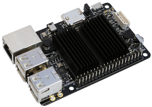
You can install Home Assistant on any ODROID device. Depending on how many automations you plan to have, you could use a C1 for a light setup, or even an XU4 for large homes and complex rules which might involve face recognition. I'm using it on a C2 which doubles as a Kodi player without issues.

The current Home Assistant version (0.71) requires Python 3.6. You can install it on Ubuntu 18.04 with the "virtualenv" installation (describerd below), which means that all the required python modules will be installed in a specific directory and will not interfere with system modules. We will also use a distinct user for Home Assistant. There are also Docker images available which we can use with Ubuntu 16.04. The complete instructions with comments are available at https://www.home-assistant.io/docs/installation/virtualenv/.

$ sudo apt-get update
$ sudo apt-get dist-upgrade
$ sudo apt-get install python-pip python3-dev
$ sudo pip install --upgrade virtualenv
$ sudo adduser --system homeassistant
$ sudo addgroup homeassistant
$ sudo usermod -G dialout -a homeassistant
$ sudo mkdir /srv/homeassistant
$ sudo chown homeassistant:homeassistant /srv/homeassistant
$ sudo su -s /bin/bash homeassistant
$ virtualenv -p python3 /srv/homeassistant
$ source /srv/homeassistant/bin/activate (homeassistant)$ pip3 install --upgrade homeassistant
$ exit
If you want to use Home Assistant without docker on Ubuntu 16.04, you can install a Python 3.6 PPA (https://launchpad.net/~jonathonf/+archive/ubuntu/python-3.6) and initialize the virtualenv with it like this:
$ sudo add-apt-repository ppa:jonathonf/python-3.6
$ sudo apt-get update
$ sudo apt-get install python3.6
$ sudo apt-get dist-upgrade
$ sudo apt-get install python-pip python3.6-dev
$ sudo pip install --upgrade virtualenv
$ sudo adduser --system homeassistant
$ sudo addgroup homeassistant
$ sudo usermod -G dialout -a homeassistant
$ sudo mkdir /srv/homeassistant
$ sudo chown homeassistant:homeassistant /srv/homeassistant
$ sudo su -s /bin/bash homeassistant
$ virtualenv -p python3.6 /srv/homeassistant
$ source /srv/homeassistant/bin/activate
(homeassistant)$ pip3 install --upgrade homeassistant
$ exit
In order to start and manage the process, it's best to create a systemd service to handle it:
$ sudo vi /etc/systemd/system/homeassistant.service
[Unit]
Description=Home Assistant
After=network.target time-sync.target
Requires=time-sync.target

[Service]
Type=simple
User=%i
ExecStart=/srv/homeassistant/bin/hass -c "/home/homeassistant/.homeassistant"

[Install]
WantedBy=multi-user.target
In order to start Home Assistant, simply start its service:
$ sudo service homeassistant start
$ sudo service homeassistant enable
Note that if you will be using components that need HTTPS, you will need to have time correctly set up at boot, so that the certificates are valid. The service startup depends on systemd-timesyncd, which in turn depends on ntp *not* being installed:
$ sudo apt-get remove ntpwebn 
$ sudo service systemd-timesyncd restart
$ sudo systemctl enable systemd-timesyncd
In case of problems, you will be able to review the logs through journalctl:
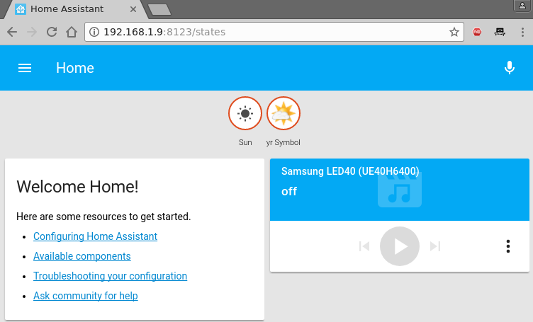
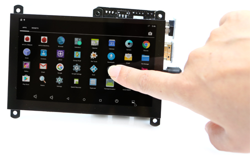
$ sudo journalctl -u homeassistant -f
Once the process starts, you will be able to connect to http://odroid-ip:8123/. Note that the first startup (or a startup following an update) might be slower, so leave it run for a few minutes until accessing the web interface. Home userAssistant also provides a native app for IOS (http://apple.co/2tYi2WI), while for Android clients you can pin the page as a homescreen launcher (Chrome -> navigate to http://odroid-ip:8123 -> Menu -> Add to homescreen).

Figure 1 - Home Assistant startup page

The configuration file

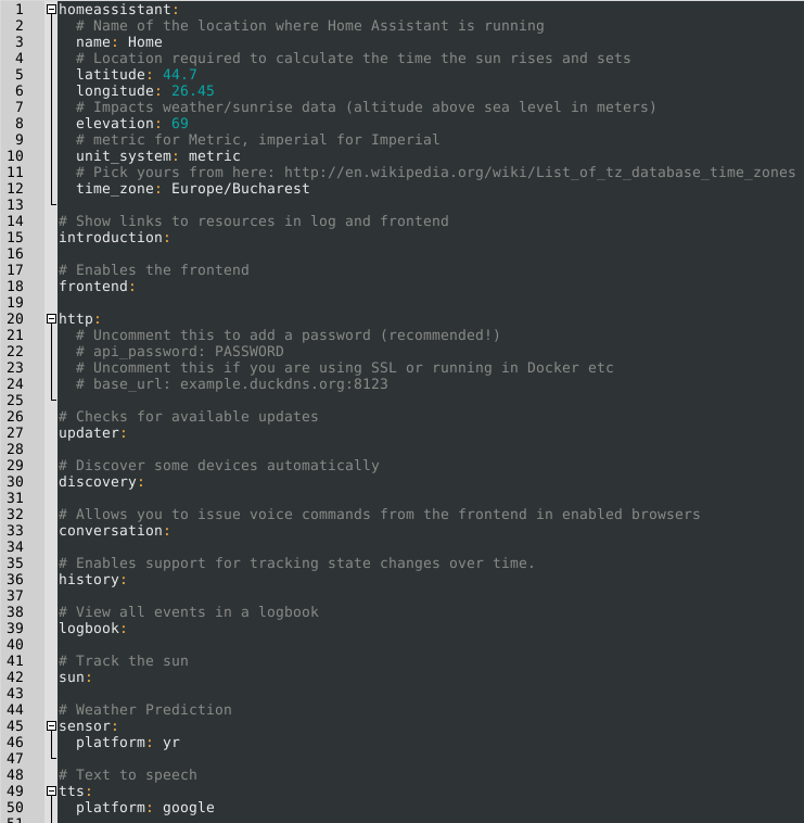
In order to set up components and configure your installation, you'll have to work a lot with Home Assistant's configuration file(s). You can manage some of the configuration from the web interface, but for now, you'll need a text editor. The main file is /home/homeassistant/.homeassistant/configuration.yaml. Its format is YAML - which stands for "Yet Another Markup Language". Like Python, it uses white space (not tabs!) to delimit sections of code. By default it uses a two space indentation for nested sections. In case you get into trouble, you will receive error messages when starting the service. You can validate the syntax with a service like http://www.yamllint.com/ which will let you know where you went wrong. There is also a troubleshooting guide at https://www.home-assistant.io/docs/configuration/troubleshooting/.

Once you've made changes to the configuration file, you will need to restart the homeassistant service to apply those changes. You can do this either from the shell with sudo service homeassistant restart, or from HA's web interface, by clicking the top left icon, selecting the "Configuration" icon and calling the "Restart" option from the "Server Management" section. The video, How To Configure Home Assistant" shows some tips you should consider when editing the configuration.

Figure 2 - The default configuration

If you plan on using HA from outside the LAN (e.g. from the Internet), you have several options. One of them is to enable HTTPS support and forward port 8123 on your router. This gives you encryption, but exposes your installation to the internet (and there might be vulnerabilities that could allow attackers take control of your system/LAN). A second option (which I prefer) is to set up a VPN on your router (or even on your ODROID) that allows you to connect and access HA (and other LAN resources) securely.

If you want to use HTTPS, in order for all features to work you will need to supply valid SSL certificates (not self-signed). In order to get valid certificates you will need to have a public DNS name (e.g. by using a dynamic DNS service like duckdns.org) and use letsencrypt.org to set up a valid SSL certificate for your installation. Step by step details can be found in the video, "Port Forwarding, DNS, and Encryption - How To Secure Home Assistant with DuckDNS and Let's Encrypt". If you must use self-signed certificates, there is a guide available at https://www.home-assistant.io/docs/ecosystem/certificates/tls_self_signed_certificate/.

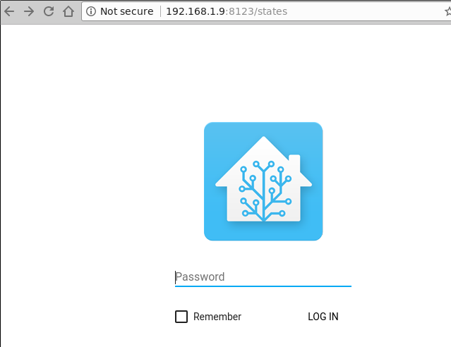
Regardless of access mechanism (http or https), you will want to set up a password. HA doesn't support multiple user accounts yet, but you can set an API Password that you will need to log into the web interface. The best way to do this is to create a file that will keep all your sensitive data (like passwords and URLs), name it “secrets.yaml” and reference it in the configuration.yaml file.

$ cat /home/homeassistant/.homeassistant/secrets.yaml api_password: odroid
$ cat /home/homeassistant/.homeassistant/configuration.yaml
 …
 http:
 api_password: !secret api_password
 …
Now, when you will restart HA, you will be asked for a password. More details about secrets may be found at https://www.home-assistant.io/docs/configuration/secrets/.

Figure 3 - Authentication

In order to get acquainted with how HA configuration works, we will set up some components. I want to set up weather, some IP cameras, Kodi and MPD, presence detection based on WiFi and also a 1-wire temperature sensor connected to the ODROID.

Weather from Darksky

There are several weather providers already integrated in HA (http://bit.ly/2t4l1Rh), so you can pick your favourite. I'm going with DarkSky (http://bit.ly/2t4gq0S), which provides quite accurate forecasts for my area. You should consult the component's help page for details about configuration and which variables you can use. You will need to register with Dark Sky and get an API Key which will let you make 1000 calls per day for free. It's best to save this API Key inside your secrets.yaml file (replace with your own key):

darksky_api_key: 87f15cbb811204412cc75109777ea5cf
The configuration has several variables, most of which are optional, however, under configuration.yaml, under the sensor section you would have the following (feel free to delete the “platform: yr” entry):
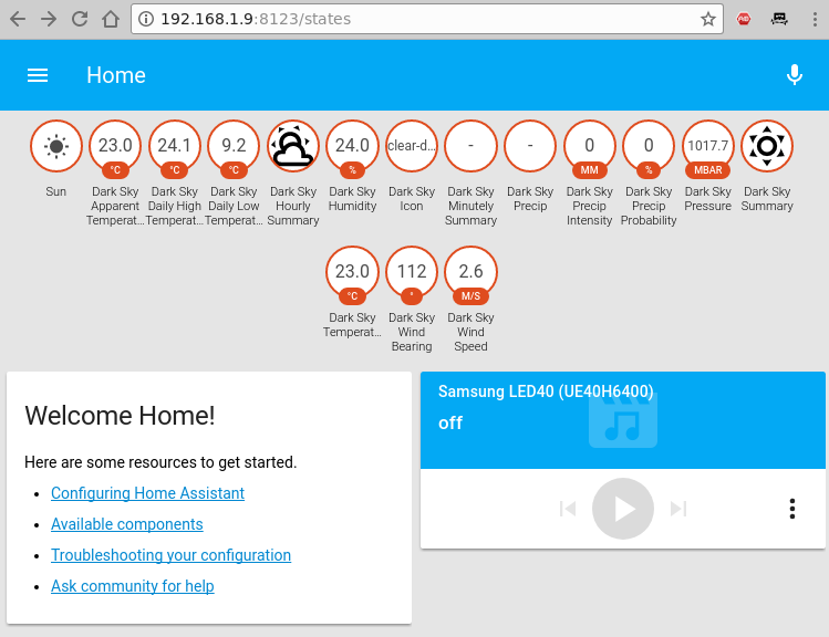
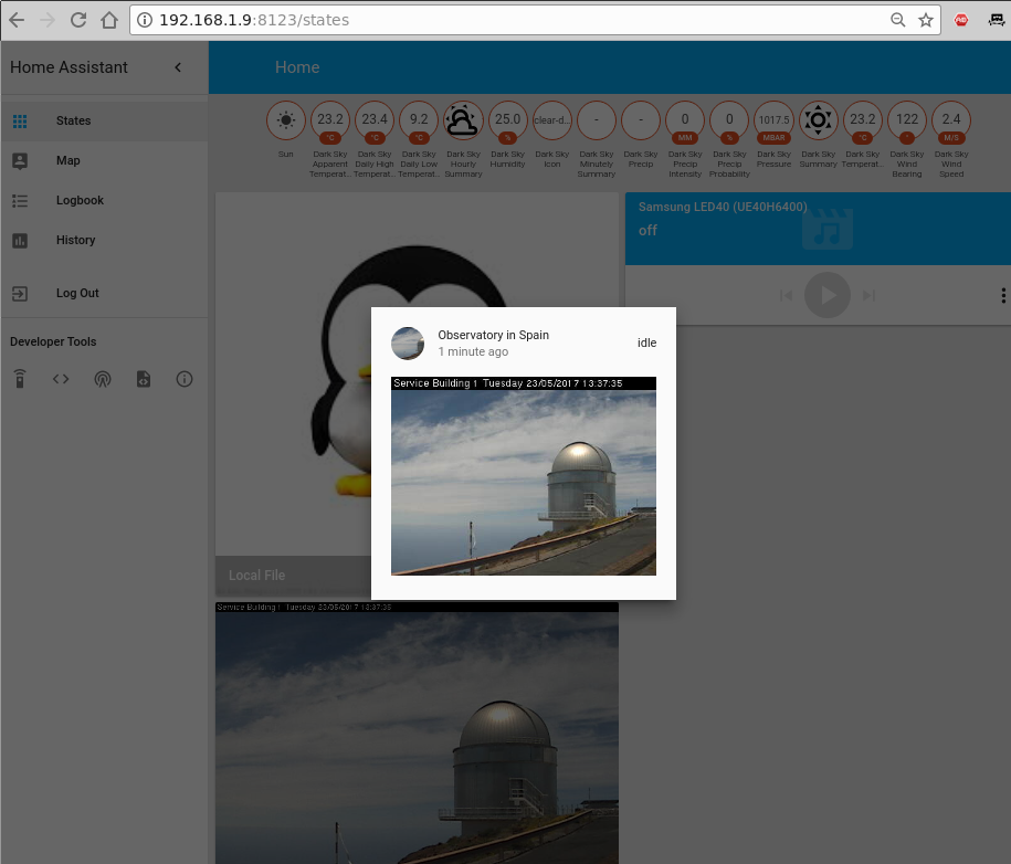
sensor:
 - platform: darksky
 api_key: !secret darksky_api_key
 name: Dark Sky
 language: ro
 monitored_conditions:
 - summary
 - precip_type
 - precip_probability
 - temperature
 - apparent_temperature
 - humidity
 - precip_intensity
 - wind_speed
 - pressure
 - wind_bearing
 - apparent_temperature
 - icon
 - minutely_summary
 - hourly_summary
 - temperature_high
 - temperature_low
 - apparent_temperature_high
 - apparent_temperature_low
 units: si
 update_interval: '00:15'
The code is mostly self-explanatory. It configures a new platform of the type "darksky", with a specific name (optional) and api_key (required) and pulls a set of parameters (monitored_conditions) from the weather provider every 15 minutes. Your actual location is taken from the latitude/longitude parameters under homeassistant, so make sure that's correct. After you restart the homeassistant service, you should be able to see the monitored variables as badges on the top of your window. Clicking on a badge will show you how that particular value has changed over time.

Figure 4 - Weather data

Viewing IP cameras

HA supports a lot of cameras (http://bit.ly/2t4DtsD), including reading data from a file, which could be used to display a graph, or visual data generated by other tools. We will be using the Generic MJPG Camera (http://bit.ly/2t4tIKM) component and the Local File (http://bit.ly/2s4Y5w4) component.

The camera we want to monitor is available at http://bit.ly/2t4cHkc (it's a public webcam), which we should add to the secrets.yaml file.

camera1_stream_url: http://iris.not.iac.es/axis-cgi/mjpg/video.cgi?resolution=320x240
camera1_still_url: http://iris.not.iac.es/jpg/image.jpg
The configuration part inside configuration.yaml looks like this for both cameras:
camera:
 - platform: mjpeg
 mjpeg_url: !secret camera1_stream_url
 still_image_url: !secret camera1_still_url
 name: Observatory in Spain
 - platform: local_file
 file_path: /tmp/tux.jpg
As usual, you will need to restart the HA service to reread the configuration (this might be a good time to comment out the “introduction” component as well). Note that when you click on a webcam you will see a live feed, otherwise the still image is updated every 10 seconds.

Figure 5 - Webcams!
Figure 5 - Webcams!

So, what can you do with these configured webcams apart from looking at them? Well, you can use them with other components such as OpenCV (http://bit.ly/2s4UUEJ) to generate triggers when certain faces are seen, or Seven Segments Display (http://bit.ly/2sAbOP0), which can take readings of various digital displays.

Kodi and MPD

To configure media players, you can look under the Media Player component list at http://bit.ly/2s0IAtQ. To configure Kodi (http://bit.ly/2sA5qr6), you will need to enable the "Allow remote control via HTTP" option (http://bit.ly/2t4cYne) and set an appropriate username and password first. To do so, add the user and password to the secrets.yaml file:

kodi_user: kodi
kodi_pass: kodi
Then, edit configuration.yaml:
media_player:
- platform: kodi
host: 192.168.1.140
name: Kodi Livingroom
username: !secret kodi_user
password: !secret kodi_pass
To configure MPD, assuming that you already have a MPD server in your network, add the MPD component (http://bit.ly/2s5sbzE) and add the password to secrets.yaml:
mpd_secret: mpd
And next, edit configuration.yaml:
media_player:
...
- platform: mpd
host: 192.168.1.140
name: MPD Living
password: !secret mpd_secret
After you restart Home Assistant, you will get the two new media players and be able to see their state (playing/stopped), control volume and even change the current playlist or use the text-to-speech component to have the media player "speak" what you want.

Figure 6 - Media players

Presence detection

The presence detection components (http://bit.ly/2t0Gt8H) try to track people's locations so that you can apply geofencing rules (e.g. do something if a person enters or leaves a location). Usually tracking is done by detecting devices connected to a router (via wifi), or via bluetooth proximity (http://bit.ly/2s0Sqfw), or by using location services such as Owntracks (http://bit.ly/2rLQdR1).

We will use a router-based tracker that, depending on your router, periodically connects to the management interface of your router, lists the ARP table, and discovers which devices are connected. A lot of router types are supported, from high-end vendors like Cisco, to consumer-grade routers like Asus, Netgear and TP-Link. Even open-source firmwares are supported, like OpenWRT, DD-WRT and Tomato.

We will be using an Asus router with SSH enabled, so we need the ASUSWRT component: http://bit.ly/2s4T32Q. You can chose to login with username/password or setup an SSH key and log in with a key instead. Note that certain firmware versions enable security measures which limit the number of SSH connections, and can blacklist your IP if a lot of connections are initiated.

As usual, we will set private data (such as the path to the key or the ssh password) in the secrets.yaml file:

router_user: admin
router_password: my_secret_password
Inside configuration.yaml add the following section:
device_tracker:
- platform: asuswrt
host: 192.168.1.1
username: !secret router_user
password: !secret router_password
interval_seconds: 120
consider_home: 300
track_new_devices: yes
The device tracker configuration page (http://bit.ly/2s4WPcA) gives more details about what options you can use. The interval_seconds option is the time between scans (2 minutes) and the consider_home option keeps you "at home" even if your devices is not seen for 300 seconds.

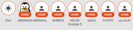
Once you restart HA, after the initial discovery is done a new file will be created, called known_devices.yaml. Here you will be able to assign a friendly name and even a picture to a specific device, or have other devices be ignored.

One entry in known_devices.yaml may look like this:

aldebaran:
hide_if_away: false
mac: 00:1E:06:31:8C:5B
name: aldebaran
picture: /local/aldebaran.png
track: true
vendor: WIBRAIN
Notice that I added a path to local picture which is stored in /home/homeassistant/.homeassistant/www/aldebaran.png. You can create the “www” folder with the following command:
$ sudo mkdir /home/homeassistant/.homeassistant/www
If there are devices which you don't want to monitor, you can set “track: false” in the known_devices.yaml file.

Figure 7 - Initial discovery/Customized entries

Measuring temperature

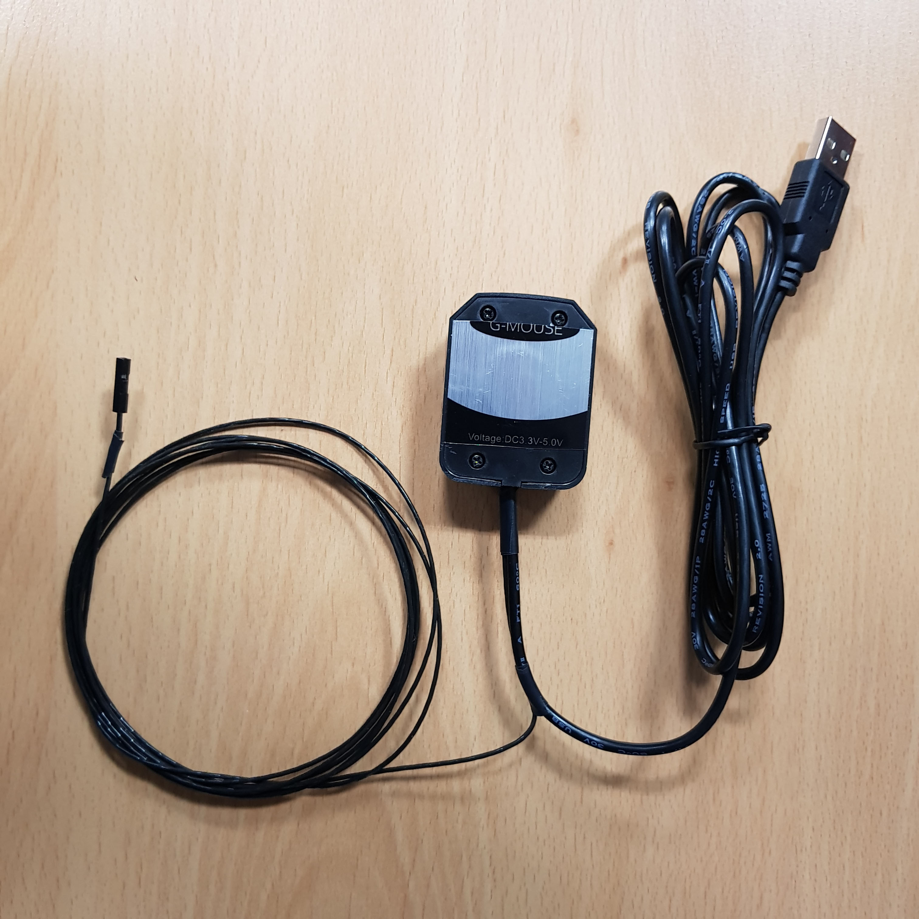
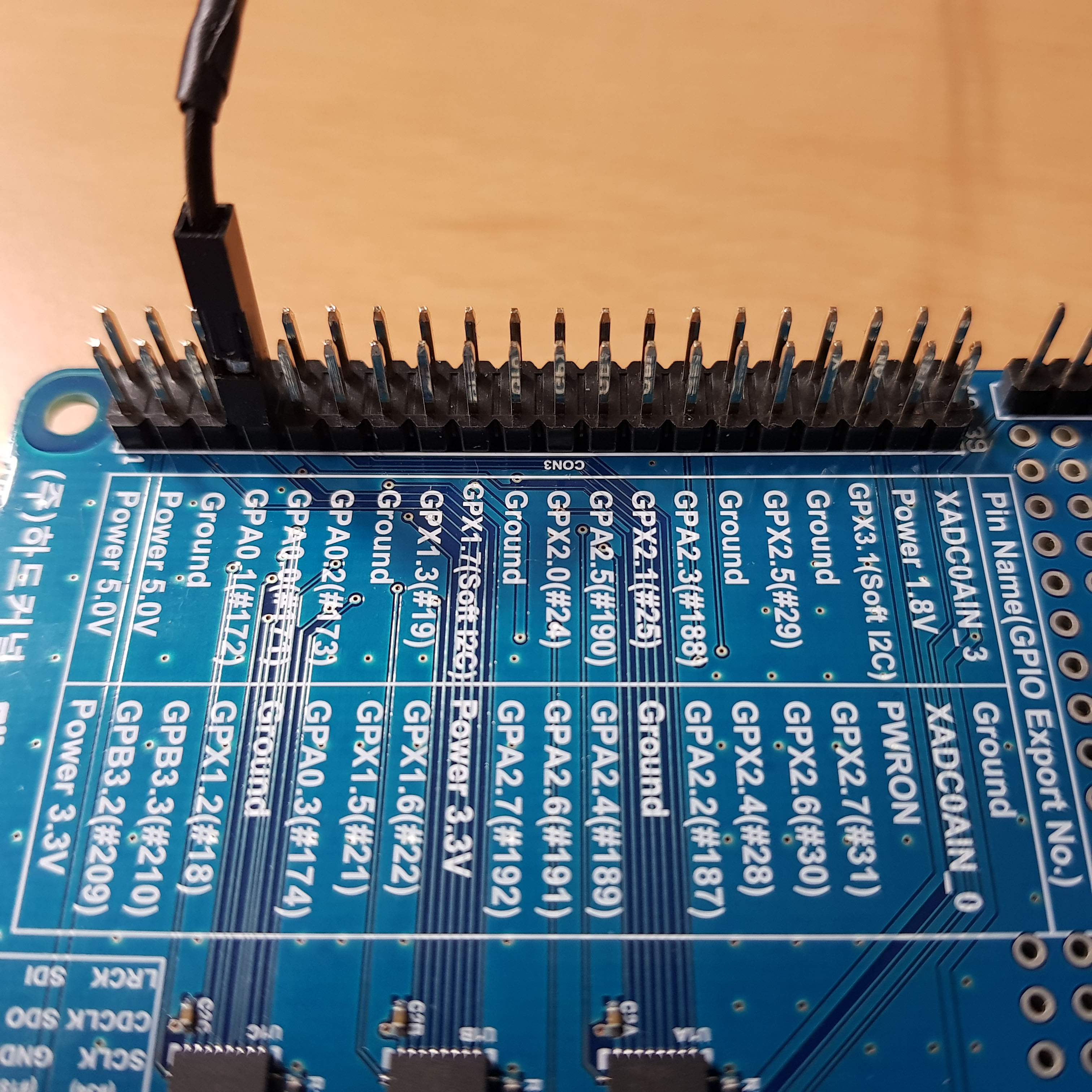
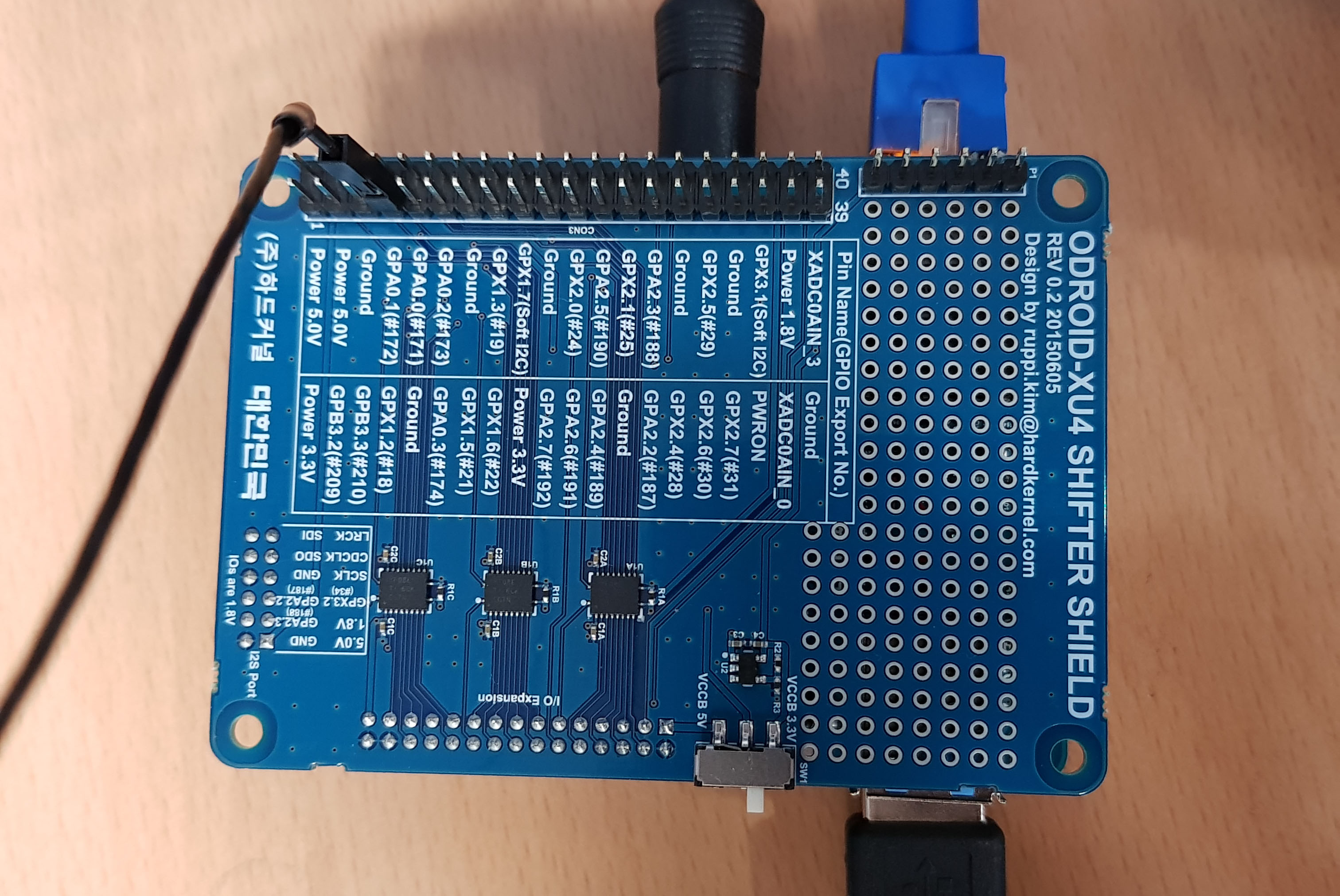
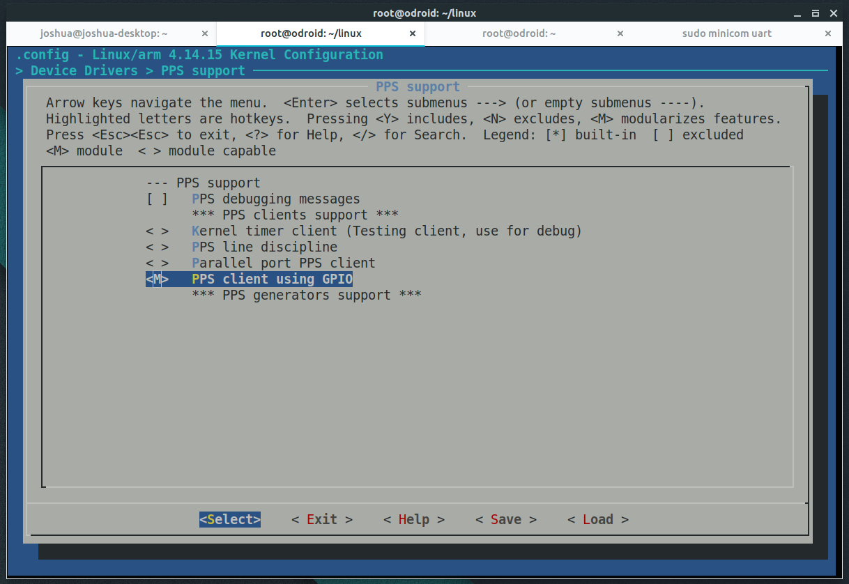
A very powerful feature of Home Assistant is the ability to track all sorts of sensors (http://bit.ly/2cNb4gJ). We want to monitor a temperature sensor based on the 1 wire protocol, connected locally to the ODROID (http://bit.ly/2s12ZPx). Before adding the sensor in HA, make sure it’s readable from the command line. You can follow the setup guide on the wiki at http://bit.ly/2s0zbTp.

You will need to know the sensor’s ID in order to add it to HA:

$ ls /sys/bus/w1/devices/
28-0516866e14ff w1_bus_master1
$ cat /sys/bus/w1/devices/28-0516866e14ff/w1_slave
92 01 4b 46 7f ff 0c 10 b5 : crc=b5 YES
92 01 4b 46 7f ff 0c 10 b5 t=25125
Next, you can make the following changes in configuration.yaml and poll the sensor every 5 minutes:
sensor:
...
- platform: onewire
names:
28-0516866e14ff: Living room
scan_interval: '00:05'
After restarting HA, the new reading will be visible in the web interface as a badge in the top part of the page.

Sorting the views

You will notice that once you start adding a few components, the web interface starts to get messy with a lot of items scattered everywhere. You can use groups and views to clean up the interface and put related items in their own tab. To understand what needs to be done, let's clear the vocabulary.

Entities are variables which provide data, such as a sensor or switch. Platforms (like dark_sky) usually provide access to multiple entities (min/max temperatures or forecast). You can view a list of entities, their names and their value if you navigate in the web interface under Developer tools -> States (<>) -> Entities.

A group is simply an object that holds a list of entities. Visually, a group is rendered as a panel, or a card. By default the group “group.all_devices” exists and holds the items discovered by a device tracker platform. Groups usually contain a list of entities.

A view is rendered as a separate tab inside Home Assistant. Views are actually groups of groups and differ from regular groups by having the property of "view: yes". You can also add individual entities, as well as groups to a view.

We will group our existing sensors into the following categories:

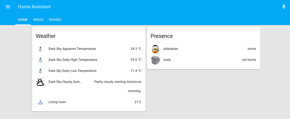
  • The first tab is called Home and contains the following groups (it will be internally called default_view, so that it is displayed when you log in):
    • Weather data
    • Presence information
    • System information (to show you if there are updates available)
  • The second tab is called Media and contains the following groups:
    • Media players
  • The final tab is called Images and contains:
    • Webcams

The configuration looks similar to the list above:

group:
default_view:
view: yes
entities:
 - group.weather
 - group.presence
 - group.systeminfo
media:
view: yes
entities:
 - group.mediaplayers
images:
view: yes
entities:
 - camera.observatory_in_spain
 - camera.local_file
weather:
name: Weather
entities:
 - sensor.dark_sky_apparent_temperature
 - sensor.dark_sky_daytime_high_apparent_temperature
 - sensor.dark_sky_daily_low_temperature
 - sensor.dark_sky_overnight_low_apparent_temperature
 - sensor.dark_sky_hourly_summary
 - sensor.living_room
presence:
name: Presence
entities:
 - device_tracker.aldebaran
 - device_tracker.nutty
systeminfo:
name: System Info
entities:
 - updater.updater
mediaplayers:
name: Media Players
entities:
 - media_player.mpd_livingroom
 - media_player.kodi_livingroom
Figure 8 - A cleaner interface with views and groups

More details about groups and layout are available in the video at http://bit.ly/2s5d6xT.

Updates

Since Home Assistant was not installed via apt-get, you will need to handle updates manually. Before updating, it's best to read the release notes and verify that the update is not breaking any previous configurations, since the configuration for new components sometimes gets redesigned, which means you’ll need to redo it. You can get a notification for a new version by using the updater.updater entity which periodically checks for newer versions and can display them inside Home Assistant. Updates are pretty frequent, and you can expect a major version every 2-3 weeks. The update procedure is simple, and details can be found at http://bit.ly/2s0Kn24.

$ sudo service homeassistant stop
$ sudo su -s /bin/bash homeassistant
$ source /srv/homeassistant/bin/activate (homeassistant)$ pip3 install --upgrade homeassistant (homeassistant)$ exit
$ sudo service homeassistant start
If you've installed via docker, you can pull a new image:
$ sudo docker pull homeassistant/raspberrypi3-homeassistant:0.72.0 
In subsequent articles, we will look at setting up more complex components like a remote relay or an air conditioning unit, setting up automations, and setting up a dashboard. For comments, questions and suggestions, please visit the support thread at http://bit.ly/2s13GbB.

ODROID-N1 vs ODROID-XU4: A Real-World Benchmark Comparison

ODROID-N1 benchmark

In keeping with their timely innovations, Hardkernel has just announced their latest SBC offering, the ODROID-N1, based on the Rockchip RK3399 SOC (http://goo.gl/2BpMuQ). Here is a very early and quick real world comparison of the ODROID-N1 with their current flagship offering, the ODROID-XU4. Note that the ODROID-N1 tested here is an engineering sample and not a released product. It is running Debian on the interim kernel 4.4 and there has not been adequate time to fully tune its OS or crypto algorithms, and other relevant components. However, some very interesting results have been observed.

The head to head comparison comprised of a single ODROID-N1 and a ODROID-XU4 pool mining (stratum server) Verium (VRM) at sustainable frequency settings. At an ambient temperature of 71 0F (21.66 0C), the ODROID-XU4 running at 1.7Ghz maintained an average temperature in the 70’s 0C and while the ODROID-N1 at 1.99Ghz never saw its temperature exceed 51 0C. The ODROID-N1 feels like a refrigerator in disguise.

The tools used include:

  • odroid-cpu-control
  • cpuminer-fireworm

The results listed below have been formatted for better readability.

ODROID-N1 results

odroid@odroid-n1:~$ uname -a
Linux odroid-n1 4.4.112 #2 SMP Thu Feb 8 21:25:35 -02 2018 aarch64 GNU/Linux

odroid@odroid-n1:~$ odroid-cpu-control -l
CPU0: governor ondemand current 408.00MHz       
 min 408.00MHz [408.00MHz]  max 1.51GHz [1.51GHz]
CPU1: governor ondemand current 408.00MHz       
 min 408.00MHz [408.00MHz]  max 1.51GHz [1.51GHz]
CPU2: governor ondemand current 408.00MHz       
 min 408.00MHz [408.00MHz]  max 1.51GHz [1.51GHz]
CPU3: governor ondemand current 408.00MHz       
 min 408.00MHz [408.00MHz]  max 1.51GHz [1.51GHz]
CPU4: governor ondemand current 408.00MHz       
 min 408.00MHz [408.00MHz]  max 1.99GHz [1.99GHz]
CPU5: governor ondemand current 408.00MHz       
 min 408.00MHz [408.00MHz]  max 1.99GHz [1.99GHz]

odroid@odroid-n1:~$ ~/cpuminer-fireworm -o stratum+tcp://stratum.poolsloth.com:3333 -u xxxx -p xxxx --randomize --no-redirect -t 9

 Verium Miner forked from cpuminer 1.4 {fireworm} by fireworm@github **
              credits to tpruvot et al. & effectsToCause et al. **

[2018-02-18 18:31:05] Starting Stratum on stratum+tcp://stratum.poolsloth.com:3333
[2018-02-18 18:31:05] HugePages unavailable (22)

[2018-02-18 18:31:05] 9 miner threads started, using scrypt algorithm.
[2018-02-18 18:31:09] Stratum difficulty set to 0.025
[2018-02-18 18:31:09] stratum.poolsloth.com:3333 scrypt² block 181936
[2018-02-18 18:32:39] Total: 538.110 H/m
[2018-02-18 18:32:59] accepted: 1/1 (100.00%), 0.00837 kH/s yes!
[2018-02-18 18:33:10] Total: 479.410 H/m
[2018-02-18 18:33:43] Total: 530.087 H/m
[2018-02-18 18:35:03] Total: 512.673 H/m
[2018-02-18 18:35:10] accepted: 2/2 (100.00%), 0.00822 kH/s yes!
[2018-02-18 18:36:04] Stratum difficulty set to 0.0171756
[2018-02-18 18:36:39] Total: 534.344 H/m
[2018-02-18 18:37:08] accepted: 3/3 (100.00%), 0.00829 kH/s yes!
[2018-02-18 18:37:31] accepted: 4/4 (100.00%), 0.00932 kH/s yes!
[2018-02-18 18:38:09] Total: 558.247 H/m
[2018-02-18 18:39:40] Total: 536.414 H/m
[2018-02-18 18:41:00] accepted: 5/5 (100.00%), 0.00915 kH/s yes!
[2018-02-18 18:41:02] Total: 537.398 H/m
[2018-02-18 18:41:21] accepted: 6/6 (100.00%), 0.00825 kH/s yes!
[2018-02-18 18:42:40] Total: 555.318 H/m
[2018-02-18 18:44:06] Total: 533.703 H/m
[2018-02-18 18:44:48] accepted: 7/7 (100.00%), 0.00930 kH/s yes!
^C
[2018-02-18 18:45:08] SIGINT received, exiting

Odroid XU4 results

root@c3n0:~# uname -a
Linux c3n0 4.14.5-92 #1 SMP PREEMPT Mon Dec 11 15:48:15 UTC 2017 armv7l armv7l armv7l GNU/Linux

root@c3n0:~# odroid-cpu-control -l
CPU0: governor performance      
    current 1.40GHz min 200.00MHz [200.00MHz]  max 1.40GHz [1.40GHz]
CPU1: governor performance      
    current 1.40GHz min 200.00MHz [200.00MHz]  max 1.40GHz [1.40GHz]
CPU2: governor performance      
    current 1.40GHz min 200.00MHz [200.00MHz]  max 1.40GHz [1.40GHz]
CPU3: governor performance      
    current 1.40GHz min 200.00MHz [200.00MHz]  max 1.40GHz [1.40GHz]
CPU4: governor performance      
    current 1.70GHz min 200.00MHz [200.00MHz]  max 1.70GHz [2.00GHz]
CPU5: governor performance      
    current 1.70GHz min 200.00MHz [200.00MHz]  max 1.70GHz [2.00GHz]
CPU6: governor performance      
    current 1.70GHz min 200.00MHz [200.00MHz]  max 1.70GHz [2.00GHz]
CPU7: governor performance      
    current 1.70GHz min 200.00MHz [200.00MHz]  max 1.70GHz [2.00GHz]

root@c3n0:~# ~/cpuminer-fireworm -o stratum+tcp://stratum.poolsloth.com:3333 -u xxxx -p xxxx --randomize --no-redirect -t 4 -1 2 --cpu-affinity-stride 1 --cpu-affinity-default-index 4 --cpu-affinity-oneway-index 0

 Verium Miner forked from cpuminer 1.4 {fireworm} by fireworm@github **
          credits to tpruvot et al. & effectsToCause et al. **

[2018-02-18 18:31:05] Starting Stratum on stratum+tcp://stratum.poolsloth.com:3333
[2018-02-18 18:31:05] Binding thread 0 to cpu index 0
[2018-02-18 18:31:05] Binding thread 1 to cpu index 0
[2018-02-18 18:31:05] HugePages unavailable (22)

[2018-02-18 18:31:05] Binding thread 2 to cpu index 0
[2018-02-18 18:31:05] Binding thread 3 to cpu index 0
[2018-02-18 18:31:05] 6 miner threads started, using 'scrypt²' algorithm.
[2018-02-18 18:31:05] Binding thread 4 to cpu index 0
[2018-02-18 18:31:05] Binding thread 5 to cpu index 0
[2018-02-18 18:31:09] Stratum difficulty set to 0.025
[2018-02-18 18:31:09] stratum.poolsloth.com:3333 scrypt² block 181936
[2018-02-18 18:31:43] Total: 388.377 H/m
[2018-02-18 18:32:14] Total: 387.199 H/m
[2018-02-18 18:32:45] Total: 387.127 H/m
[2018-02-18 18:33:16] Total: 384.155 H/m
[2018-02-18 18:33:47] Total: 385.000 H/m
[2018-02-18 18:34:18] Total: 385.126 H/m
[2018-02-18 18:34:49] Total: 384.142 H/m
[2018-02-18 18:35:20] Total: 383.299 H/m
[2018-02-18 18:35:51] Total: 383.115 H/m
[2018-02-18 18:36:22] Total: 384.423 H/m
[2018-02-18 18:36:54] Total: 385.171 H/m
[2018-02-18 18:37:25] Total: 385.309 H/m
[2018-02-18 18:37:35] accepted: 1/1 (100.00%), 0.00640 kH/s yes!
[2018-02-18 18:37:39] accepted: 2/2 (100.00%), 0.00639 kH/s yes!
[2018-02-18 18:37:44] accepted: 3/3 (100.00%), 0.00639 kH/s yes!
[2018-02-18 18:37:56] Total: 383.180 H/m
[2018-02-18 18:38:27] Total: 382.897 H/m
[2018-02-18 18:38:58] Total: 382.540 H/m
[2018-02-18 18:39:29] Total: 383.798 H/m
[2018-02-18 18:40:00] Total: 383.192 H/m
[2018-02-18 18:40:31] Total: 383.481 H/m
[2018-02-18 18:41:02] Total: 383.795 H/m
[2018-02-18 18:41:33] Total: 384.514 H/m
[2018-02-18 18:42:04] Total: 383.588 H/m
[2018-02-18 18:42:35] Total: 383.282 H/m
[2018-02-18 18:43:07] Total: 382.776 H/m
[2018-02-18 18:43:38] Total: 383.951 H/m
[2018-02-18 18:44:09] Total: 384.540 H/m
[2018-02-18 18:44:13] accepted: 4/4 (100.00%), 0.00642 kH/s yes!
[2018-02-18 18:44:17] Stratum difficulty set to 0.0169173
[2018-02-18 18:44:29] accepted: 5/5 (100.00%), 0.00642 kH/s yes!
[2018-02-18 18:44:40] Total: 385.162 H/m
^C
[2018-02-18 18:45:04] SIGINT received, exiting
The average hash rate for the ODROID-N1 was 531.57 H/m and 384.35 H/m for the ODROID-XU4. It indicates that there is a 38.3% increase in hash rate for the ODROID-N1 in real world operations. I only spent a relatively short amount of time quickly going through a bunch of thread and core combinations on the ODROID-N1, so there is bound to be some room for improvement. Even though the ODROID-N1 was running 9, 3-way threads for the test, I was successful in running 24 1-way threads. I did not try any higher number of 1-way threads because the performance was deteriorating. It just demonstrates the flexibility and advantage of having 4GB of RAM (memory). In the future, a 6-way thread test can be performed to study the issue further. For the record, even though the ODROID-XU4 was running at 2Ghz, the hash rate was lower and unsustainable.
root@c3n0:~# odroid-cpu-control -s -M 2.0G
CPU0: max 1.40GHz [1.40GHz] -> 1.40GHz [1.40GHz]
CPU1: max 1.40GHz [1.40GHz] -> 1.40GHz [1.40GHz]
CPU2: max 1.40GHz [1.40GHz] -> 1.40GHz [1.40GHz]
CPU3: max 1.40GHz [1.40GHz] -> 1.40GHz [1.40GHz]
CPU4: max 1.70GHz [2.00GHz] -> 2.00GHz [2.00GHz]
CPU5: max 1.70GHz [2.00GHz] -> 2.00GHz [2.00GHz]
CPU6: max 1.70GHz [2.00GHz] -> 2.00GHz [2.00GHz]
CPU7: max 1.70GHz [2.00GHz] -> 2.00GHz [2.00GHz]

root@c3n0:~# ~/cpuminer-fireworm -o stratum+tcp://stratum.poolsloth.com:3333 -u xxxx -p xxxx --randomize --no-redirect -t 4 -1 2

 Verium Miner forked from cpuminer 1.4 {fireworm} by fireworm@github **
              credits to tpruvot et al. & effectsToCause et al. **

[2018-02-18 20:37:32] Starting Stratum on stratum+tcp://stratum.poolsloth.com:3333
[2018-02-18 20:37:32] HugePages unavailable (22)

[2018-02-18 20:37:32] 6 miner threads started, using 'scrypt²' algorithm.
[2018-02-18 20:37:36] Stratum difficulty set to 0.025
[2018-02-18 20:37:36] stratum.poolsloth.com:3333 scrypt² block 181963
[2018-02-18 20:37:42] accepted: 1/1 (100.00%), 0.00429 kH/s yes!
[2018-02-18 20:38:31] accepted: 2/2 (100.00%), 0.00642 kH/s yes!
[2018-02-18 20:38:48] Total: 356.060 H/m
[2018-02-18 20:39:58] Total: 357.322 H/m
[2018-02-18 20:41:01] Total: 353.908 H/m
[2018-02-18 20:41:02] accepted: 3/3 (100.00%), 0.00590 kH/s yes!
[2018-02-18 20:41:32] accepted: 4/4 (100.00%), 0.00611 kH/s yes!
[2018-02-18 20:42:12] Total: 347.295 H/m
^C
[2018-02-18 20:42:18] SIGINT received, exiting
Another good point of reference for comparison is KaptainBlaZzed's hardware hash rate comparison sheet for VRM at http://goo.gl/hrYs2Q. On the second sheet, accessed by the tab at the bottom, there is a comparison of other SBC's. Again, some context is in order. My ODROID-XU4 posted hash rate is for solo mining (get-work not a stratum server) and is a sustainable hash rate at 1.7Ghz. If someone has improved their cooling, has better OS or crypto-algorithm tuning, they could possibly see better hash rates. At the far right of the spreadsheet you can see the Hashes/Watt results which also shed some light on the efficiency of the SBC's. One other important number missing is the Hashes/Dollar (capital cost). It is another area that the ODROID SBC's in general are at or near the top.

Observations

It appears the PoP memory could be affecting system thermal profiles. For the moment at least, based on the thermal profiles of the ODROID-XU4 and the likes of the ODROID-MC1, they seem to be more cost-effective than ODROID-N1 for mining rigs.  For comments, questions, and suggestion, please visit the original ODROID Forum thread at https://forum.odroid.com/viewtopic.php?f=149&t=30174. Additional information about the upcoming ODROID-N1, along with updates on the production release date, is available at https://forum.odroid.com/viewtopic.php?f=149&t=29932.

Prime Number Discovery: Use an ODROID-C2 to make mathematical history

“The problem of distinguishing prime numbers from composite numbers and of resolving the latter into their prime factors is known to be one of the mostf important and useful in arithmetic.” − Carl Friedrich Gauss

In this article, I will give some background into some of the algorithmic aspects of primality testing, illustrate them using the Linux bc utility, and describe some of the advanced algorithms used in the famous Lucas-Lehmer (LL) primality test for Mersenne numbers and the author's own implementation thereof in his Mlucas program. This software program is now available in a version optimized for the vector-arithmetic hardware functionality available in the ARMv8 processor family, specifically the ODROID-C2 SBC. Note however, that the software is also buildable on non-v8 ODROID SBC’s, but just not using the vector instructions. Since the Mlucas readme page (linked further down) provides detailed build instructions for a variety of hardware platforms including ODROID SBC’s, I shall focus here on the mathematics and algorithmics, at a level which should be understandable by anyone with a basic understanding in algebra and computer programming.

Primitive roots and primality

LL is example of what is referred to as a nonfactorial primality test, which refers to the fact that it requires no knowledge whatever about the factorization-into-primes of the input number N, or modulus, though we typically perform a pre-sieving "trial factorization" step to check such numbers for small prime factors before resorting to the LL test. Such tests rely on deep algebraic properties of number fields which are beyond the scope of this article, but in essence they amount to testing whether there exists a primitive root of the mathematical group defined by multiplication modulo N, which means a root of the maximal possible order N−1. (This sounds like very highbrow mathematics, but in fact reduces to very simple terms, as we shall illustrate.) Such a root exists if and only if (i.e. the converse holds) N is prime. For example, if we compute successive powers of 2 modulo N = 7, we get the sequence 2,4,1,... which repeats with length 3, meaning that either 7 is composite or 2 is not a primitive root (mod 7). If we instead try powers of 3 we get the sequence 3,2,6,4,5,1 which is of the maximal possible length N−1 = 6 for the multiplicative group (mod 7), thus we conclude that 7 is prime by way of having found 3 to be a primitive root. If we instead try the powering sequences resulting from the same two bases modulo the composite 15 we get 2k (mod 15) = 2,4,8,1,... and 3k (mod 15) = 3,9,-3,-9,..., for index k = 1,2,3,... . We note that both sequences repeat with periodicity 4, which is firstly less than N−1 and secondly does not divide N−1 (i.e. there is no chance of one of the recurring ones in the 2k sequence landing in the N−1 slot), and that the 3k sequence does not even contain a 1, whereas both of the (mod 7) sequences contain one or more ones, in particular both having 1 in the (N−1) slot. That is, for N = 7 we have aN-1 ≡ 1 (mod N) for all bases not a multiple of 7, where the triple-bar-equals is the symbol for modular equivalence, i.e. the 2 sides of the relation are equal when reduced modulo N. For the (mod 15) sequences, on the other hand, the non-occurrence of 1 as the N−1 power in either one suffices to prove 15 composite.

Computing such power-mod sequences for large moduli is of course not practical for very large N, so the idea of instead computing just the (N−1)th power of the base is crucial, because that requires the computation of a mere O(lg N) intermediates, where lg is the binary logarithm. The resulting test turns out to be rigorous only in the sense of correctly identifying composite numbers, being merely probabilistic for primes because it yields a false-positive '1' result for a small percentage of composite moduli in addition to the prime ones, but can be modified to yield a deterministic (rigorous) test in for a usefully large fraction of these problematic false primes.

Fermat's 'little' theorem and probable-primality testing

Both rigorous primality tests and the so-called probable-primality tests are based in one way or another on the property of existence of a primitive root, and it is useful to use the probable-prime variety to illustrate the kind of arithmetic required to implement such a test, especially for large moduli. The "father of number theory", Pierre de Fermat, early in the 17th century had already observed and formalized into an actual theorem what we noted above, that for any prime p, if a is coprime to (has no factors in common with) p -- since p prime this means a must not be a multiple of p -- then

a^(p−1) ≡ 1 (mod p).  [*]
This is now referred to as Fermat's "little theorem" to differentiate it from its more-famous (but of less practical importance) "last theorem", about the solutions over the integers of the equation an+bn = cn; the resulting test applied to numbers of unknown character is referred to, interchangeably, as a Fermat probable-prime or Fermat compositeness test. The first appellation refers to the fact that an integer N satisfying aN−1 ≡ 1 (mod N) for some base a coprime to N is very likely to be prime, large-sample-statistically speaking, the second to the fact that numbers failing this criterion are certainly composite, even if an explicit factor of N has not been found.

Pierre de Fermat, the
Pierre de Fermat, the "Father of Number Theory"

Note that the converse of [*] does not hold, that is, there are coprime integer pairs a,N for which aN−1 ≡ 1 (mod N) but where N is not a prime; for example, using the linux 'bc' utility one can see that the composite N = 341 = 11 × 31 satisfies the theorem for base a = 2, by invoking bc in a command shell and simply typing '2^340%341'. This underscores the importance of trying multiple bases if the first one yields aN−1 ≡ 1 (mod N): for prime N, every integer in 2,...,N-2† is coprime to N, and thus all these bases yield 1 for the powering result, whereas for composite N, trying a small number of bases nearly always suffices to reveal N as composite. We say "nearly always" because there exists a special class of integers known as Carmichael numbers, which pass the Fermat test to all bases which are coprime to N; the smallest such is 561 = 3×11×17. Carmichael numbers only reveal their composite character if we happen to choose a base a for the Fermat test which is not coprime to N, i.e. if we find a factor of N. In practice one should always first check N for small prime factors up to some bound (set by the cost of such trial factorization) before subjecting N to a Fermat-style probable-primality test.

† We skip both 1 and N−1 as potential bases because, being ≡±1 (mod N), these two "bookend" values of a both trivially yield aN−1 ≡ 1 for all odd N.

For base a = 2 there are precisely 10403 such Fermat pseudoprimes, a miniscule number compared to the nearly 200 million primes below that bound, so even using just this single base yields a remarkably effective way of determining if a number is likely to be prime. For example, one can combine such a Fermat base-2 pseudoprime test with a prestored table of the known composites less than 232 which pass the test to produce a very efficient deterministic primality algorithm for numbers below that bound. In the more general context of testing numbers of arbitrary size, however, it is important to realize that there are certain classes of numbers, all of which are Fermat base-2 pseudoprimes, irrespective of whether they are prime or composite. The two best-known such classes are, firstly, the Mersenne numbers M(p) = 2p−1 (for which we restrict the definition to prime exponents since that is required for a number of this form to have a chance of being prime); for example, 211−1 passes the test even though it factors as 23 × 89.

The second class of such numbers is the Fermat numbers Fm = 22m+1. It appears that the fact that the first five such numbers, F0 - F4 = 3,5,17,257,65537 are small enough to be amenable to pencil-and-paper trial division and are easily shown to be primes that way coupled with the fact that they all pass the test named in his honor may have led Fermat to make his famously incorrect conjecture that all such numbers are prime. This conjecture was refuted by Euler a few decades later, via his showing that 641 is a prime factor of F5, and subsequent work has led to a general belief that in all likelihood the smallest five such numbers are in fact the only primes in the sequence. Simply changing the base of the Fermat test to, say, 3, suffices to distinguish the primes from the composites in this number sequence, but it appears this idea never occurred to Fermat.

Carl Friedrich Gauss, one of the greatest mathematicians of all time

Efficient modular exponentiation

To perform the modular exponentiation, we use a general technique - or better, related set of techniques - known as a binary powering ladder. The name refers to the fact that the various approaches here all rely on parsing the bits of the exponent represented in binary form. By way of encouraging the reader to compute alongside reading, we make use of the POSIX built-in arbitrary precision calculator, bc, which is relatively slow compared to higher-end number-theoretic freeware programs such as Pari/GP and the Gnu multiprecision library, GMP, but can be exceedingly handy for this kind of basic algorithmic 'rapid prototyping'. We invoke the calculator in default whole-number mode simply via 'bc' in a terminal; 'bc -l' invokes the calculator in floating-point mode, in which the precision can be adjusted to suit using the value of the 'scale' parameter (whose default is 20 decimal digits), and the '-l' defines the standard math library, which contains a handful of useful functions including natural logarithm and exponent, trigonometric sine, cosine and arctangent (from which other things can be built, e.g. '4*a(1)' computes π to the precision set by the current value of scale by using that arctan(1) = π/4), and the Bessel function of the first kind. The arithmetic base of bc's inputs and outputs can be controlled by modifying the values of ibase and obase from their defaults of 10, for example to view 23 in binary, type 'obase = 2; 23' which dutifully outputs 10111; reset the output base back to its decimal default via 'obase = 10'.

Note that for general - and in particular very large - moduli we cannot simply compute the power on the left-hand-side of [*] and reduce the result modulo N, since the numbers get large enough to overwhelm even our largest computing storage. Roughly speaking, the powers double in length for each bit in the exponent, so raising base 2 to a 64-bit exponent gives a result on the order of 264, or 18,446,744,073,709,551,616 bits, or over 2000 petabytes, nicely illustrating the famous wheat and chessboard problem in the mathematics of geometric series. To test a number of the size of the most-recently-discovered Mersenne prime, we need to do tens of millions of these kinds of size-doubling iterations, so how is that possible on available compute hardware? We again turn to the properties of modular arithmetic, one of the crucial ones of which is that in computing a large 'powermod' of this kind, we can do modular reduction at every step of the way, whenever it is convenient to do so. Thus in practice one uses a binary powering ladder to break the exponentiation into a series of squarings and multiplications, each step of which is followed by a modular reduction of the resulting intermediate.

We will compare and contrast two basic approaches to the binary-powering computation of ab (mod n), which run through the bits of the exponent b in opposite directions. Both do one squaring per bit of b as well as some more general multiplications whose precise count depends on the bit pattern of b, but can never exceed that of the squarings. The right-to-left method initializes an accumulator y = 1 and a current-square z = a, then for each bit in n beginning with the rightmost (ones) bit, if the current bit = 1, we up-multiply the accumulator by the current square z, then again square z to prepare for the next bit to the left. Here is a simple user-defined bc function which illustrates this - for simplicity's sake we have omitted some basic preprocessing which one would include for sanity-checking the inputs such as zero-modulus and nonnegative-exponent checks:

/*
 * right-to-left-to-right binary modpow, a^b (mod n):
 */

define modpow_rl(a,b,n) {
  
  auto y,z;
  y = 1; 
  z = a%n;

  while (b) {

     if(b%2) y = (y*z)%n;

     z = (z*z)%n;

     b /= 2;

  }

  return (y);

}
We leave it as an exercise for the reader to implement a simple optimization which adds a lookahead inside the loop such that the current-square update is only performed if there is a next leftward bit to be processed, which is useful if the base a is large but the exponent is small. After pasting the above code into your bc shell, try a base-2 Fermat pseudoprime test of the known Mersenne prime M(2203): 'n=2^2203-1; modpow_rl(2,n-1,n)' (this will take a few seconds). Now retry with a composite exponent of similar size, say 2205, and note the non-unity result indicating that n = 22205−1 is also composite. Since 2205 has small prime factors 3,5 and 7, we can further use the bc modulo function '%' to verify that this number is exactly divisible by 7,31 and 127.

Of course, we already noted that a base-2 Fermat pseudoprime test returns 'likely prime' for all Mersenne numbers, that is, for all 2p−1 with p prime, we can use the above modpow function to check this, now further modifying the return value to a binary 0 (composite) or 1 (pseudoprime to the given base): 'n=2^2207-1; modpow_rl(2,n-1,n) == 1' returns 1 even though the Mersenne number in question has a small factor, 123593 = 56×2207+1. Repeating the same Fermat pseudoprime test but now to base 3 correctly reveals this number to be composite. Note the associated jump in bc runtime - this appears to reflect some special-case optimizations in bc's internal logic related to recognizing arguments which are powers of 2 - we see a similar speed disparity when repeating the pseudoprime test using bases 4 and 5, for example.

Our next powering algorithm processes the bits in the opposite direction, left-to-right. This method initializes the accumulator y = a, corresponding to the leftmost set bit, then for each rightward bit we square y, and if the current bit = 1, we up-multiply the accumulator by the powering base a. In a coding language like C we could - either via compiler intrinsics or via a small assembly-code macro - implement the bits() functions via a binary divide-and-conquer approach or by efficiently accessing whatever hardware instruction might be available for leading-zeros-counting, and our bit-reversal function reverse() could be efficiently implemented using a small table of 256 precomputed bit-reversed bytes, a loop to do bytewise swaps at the left and right ends of our exponent, and a final step to right-shift the result from 0-7 bits, depending on where in the leftmost set byte the leftmost set bit occurs. In bc we have no such bitwise functionality and so must roll out own inefficient emulation routines, but as our focus is on large-operand modpow, the time cost of such bitwise operations is negligible compared to that of the modular multiplications:

define bits(n) {
  auto ssave, r;
  ssave = scale;  scale = 0;  /* In case we're in floating-point mode */
  r = length(n)*3321928095/1000000000;
  while ( 2^r > n ) { r -= 1; }
  scale = ssave;
  return(r+1);
}

define reverse(n,nbits) {
  auto tmp;
  tmp = 0;
  while(nbits) {
    tmp = 2*tmp + (n % 2);
    n /= 2;
    nbits -= 1;
  }
  return(tmp);
}

/* left-to-right binary modpow, a^b (mod n): */
define modpow_lr(a,b,n) {
  auto y,len;
  len = bits(b);  b = reverse(b,len);
  y = a%n;  b /= 2;
  while(--len) {
    y = (y*y)%n;
    if(b%2) y = (a*y)%n;
    b /= 2;
  }
  return(y);
}
The need for bit-reversal may also be avoided by implementing the algorithm recursively, but as bc is, shall we say, less than spiffy when it comes to efficient support for recursion, we prefer a nonrecursive algorithm in the left-to-right case. We urge readers to paste the above into their bc shell, use it to again try the base-2 and base-3 Fermat-pseudoprime tests on 22207−1, and compare those runtimes to the ones for the right-to-left algorithm. In my bc shell the left-to-right method runs in roughly half the time on the aforementioned composite Mersenne number, despite the fact that the guts of the loops in our RL and LR powering functions look quite similar, each having one mod-square and one mod-multiply.

The reason for the speedup in the LR method becomes clear when we examine precisely what operands are involved in the two respective mod-multiply operations. In the RL powering, we multiply together the current power accumulator y and the current mod-square z, both of which are the size of the modulus n. In the LR powering, we multiply together the current power accumulator y and the base a, with the latter typically being order of unity, or O(1) in standard asymptotic-order notation.

In fact, for small bases, we can replace the the a×y product by a suitably chosen series of leftward bitshift-and-accumulates of y if that proves advantageous, but the bottom line - with a view to the underlying hardware implementation of such arbitrary-precision operations via multiword arithmetic - is that in the LR algorithm we multiply the vector y by the scalar base a, which is linear in the vector length in terms of cost. For general exponents whose bits are split roughly equally between 0 and 1 we only realize this cost savings for the 1-bits, but our particular numerical example involves a Mersenne number all of whose bits are 1, thus the exponent of the binary powering n−1 has just a single 0 bit in the lowest position, and if vector-times-vector mod-square and mod-multiply cost roughly the same (as is the case for bc), replacing the latter by a vector-times-scalar cuts the runtime roughly in half, as observed.

Marin Mersenne is best known for Mersenne prime numbers, a special type of prime number

Deterministic primality proving

While the Fermat-pseudoprime test is an efficient way to identify if a given number is likely prime, our real interest is in rigorously establishing the character, prime or composite, of same. Thus it is important to supplement such probable-primality tests with deterministic alternatives whenever feasible. If said alternative can be performed for similar computational cost that is ideal, because computing aN−1 (mod N) using the modular left-to-right binary powering approach requires the computation of O(lg N) modular squarings of N-sized intermediates and a similar-sized number of modular multiplications of such intermediates by the base a, which is generally much smaller than N, meaning these supplementary scalar multiplies do not signify in terms of the overall large-N asymptotic algorithmic cost. There is reason to believe - though this has not been proven - that a cost of one modular squaring per bit of N is in fact the optimum achievable for a non-factorial primality test.

Alas, it seems that there is only a limited class of numbers of very special forms for which a deterministic primality test of similarly low computational cost exists - the most famous such are again the aforementioned two classes. For the Fermat numbers we use a generalization of the Fermat pseudoprime test due to Euler, in which one instead computes a(N−1)/2(mod N) and compares the result to ± 1, with the proper sign depending on a particular algebraic property of N. For the Fermat numbers, it suffices to take a = 3 and check whether 3(Fm−1)/2 = 322m−1 ≡ −1 (mod Fm), which requires precisely 2m−1 mod-squarings of the initial seed 3. The sufficiency of this in determining the primality of the Fermat numbers is known as Pépin's theorem. The reader can use either of the above bc modpow functions to perform the Pépin primality test on a Fermat number up to as many as several kilobits in size; for example to test the 2-kilobit F11, 'n = 2^(2^11)+1; modpow_lr(3,(n-1)/2,n) == n-1'. Note that the LR and RL algorithms run in roughly the same time on the Fermat numbers, since the power computed in the modular exponentiation of Pépin test is a power of 2, thus has just a single 1-bit in the leftmost position.

For the Mersenne numbers M(p) = 2p−1, the primality test is based on the algebraic properties of so-called Lucas sequences after the French mathematician Édouard Lucas, but was refined later by number theorist Derrick Lehmer into a simple algorithmic form known as the Lucas-Lehmer primality test: beginning with any one of an algebraically permitted initial seed values x (the most commonly used of which is 4), we perform precisely p−2 iterative updates of the form x = x2−2 (mod M(p)); the Mersenne number in question is prime if and only if the result is 0. For example, for p = 5, we have unmodded iterates 4,14,194,37634; in modded form these are 4,14,8,0, indicating that the final iterate 37634 is divisible by the modulus 31 and thus that this modulus is prime. As with our probable-primality tests and the Pépin test, we have one such iteration per bit of the modulus, give or take one or two.

To give a sense of the relative efficiencies of such specialized-modulus tests compared to deterministic primality tests for general moduli, the fastest-known of the latter are based on the arithmetic of elliptic curves and have been used to prove primality of numbers having around 20,000 decimal digits, whereas the Lucas-Lehmer and Pépin tests have, as of this writing, been performed on numbers approaching 200 million digits. Since, as we shall show below, the overall cost of the specialized tests is slightly greater than quadratic in the length of the input, this factor-of-10,000 size disparity translates into a proportionally larger effective difference in test efficiency. In terms of the specialized-modulus tests, the speed difference is roughly equivalent to a hundred-millionfold disparity in testing efficiency based on the sizes of the current record-holders for both kinds of tests.

Fast modular multiplication

Despite the superficially different forms of the above two primality tests, we note that for both the crucial performance-gating operation, just as is the case in the Fermat pseudoprime test, is modular multiplication, which is taking the product of a pair of input numbers and reducing the result modulo a third. (The additional subtract-2 operation of the LL test is negligible with regard to these large-operand asymptotic work scalings). For modest-sized inputs we can use a standard digit-by-digit "grammar school" multiply algorithm, followed by a division-with-remainder by the modulus, but again, for large numbers we must be quite a bit more clever than this.

Leonhard Euler, author of over 1000 papers, many seminal, in fields ranging from number theory to fluid mechanics to astronomy, and who on losing his eyesight in his late 40s famously (and truthfully, based on his subsequent research output) remarked,
Leonhard Euler, author of over 1000 papers, many seminal, in fields ranging from number theory to fluid mechanics to astronomy, and who on losing his eyesight in his late 40s famously (and truthfully, based on his subsequent research output) remarked, "Now I will have fewer distractions"

The key insight behind modern state-of-the-art large-integer multiplication algorithms is due to Schönhage and Strassen (see also http://numbers.computation.free.fr/Constants/Algorithms/fft.html for a more mathematical exposition of the technique), who recognized that multiplication of two integers amounts to digitwise convolution of the inputs. This insight allows any of the well-known high-efficiency convolution algorithms from the realm of digital signal processing to be brought to bear on the problem. Reflecting the evolution of the modern microprocessor, the fastest-known implementations of such algorithms use the Fast Fourier Transform (FFT) and thus make use of the floating-point hardware of the processor, despite the attendant roundoff errors which cause the convolution outputs to deviate from the pure-integer values they would have using exact arithmetic.

In spite of this inexactitude, high-quality FFT software allows one to be remarkably aggressive in how much roundoff error one can sustain without fatally corrupting the long multiplication chains involved in large-integer primality testing: for example, the Lucas-Lehmer test which discovered the most-recent record-sized Mersenne prime, 277232917−1, used a double-precision FFT which divided each of the 77232917-bit iterates into 222 input words of either 18 or 19 bits in length (precisely speaking 1735445 = 77232917 (mod 222) of the larger and the remaining 2458859 words of the smaller size), thus used slightly greater than 18 bits per input 'digit' of the discrete convolution. This gave floating-point convolution outputs having fractional parts (i.e. accumulated roundoff errors) as large as nearly 0.4, which is remarkably close to the fatal "I don't know whether to round this inexact floating-point convolution output up or down" 0.5 error level.

Nonetheless, multiple verify runs using independently developed FFT implementations at several different (and larger, hence having much smaller roundoff errors) transform lengths, on several different kinds of hardware, confirmed the correctness of the initial primality test. For an n-bit modulus, the large-n-asymptotic compute cost of such an FFT-multiply is O(n lg n), though realizing this in practice, especially when the operands get large enough to exceed the sizes of the various-level data caches used in modern microprocessors, is a far-from-insignificant algorithmic and data-movement challenge. Since our various primality tests require O(n) such multiply steps, the work estimate for an FFT-based primality test is O(n2 lg n), which is only a factor lg n larger than the quadratic cost of a single grammar-school multiply. The upshot is that to write a world-class primality-testing program, one must write (or make use of) a world-class transform-based convolution.

Roughly 20 years ago, I was on the faculty of engineering at Case Western Reserve University in Cleveland, Ohio, and was looking for an interesting way to motivate the teaching of the Fast Fourier Transform algorithm from signal processing to the students in my undergraduate computational methods class. Some online searching turned up the use of FFT in large-integer multiplication and the rest was history, as the saying goes.

The beginning of the largest prime number, discovered on December 26, 2017 by a volunteer distributed computing effort, has 23,249,425 digits

The second major algorithmic speedup in modern primality testing came roughly a generation following the Schönhage-Strassen algorithm, and involved the required FFT length needed to multiply two integers of a given size. In order to perform a modular multiply of a pair of n-bit inputs, in general we must first exactly compute the product, which is twice as many bits in length, then reduce the product (i.e. compute the remainder) with respect to the modulus in question. For specialized 'binary-friendly' moduli such as the Mersenne and Fermat numbers the reduction can be done efficiently using bitwise arithmetic, but to compute the double-width product still imposes an overhead cost, since it requires us to zero-pad our FFT-convolution inputs with n 0 bits in the upper half and use an FFT length twice as large as our eventual reduced outputs otherwise would dictate.

This all changed in 1994, when the late Richard Crandall and Barry Fagin published a paper showing how for the special cases of Mersenne and Fermat-number moduli such zero-padding could be avoided by way of cleverly weighting the transform inputs in order to effect an "implicit mod" operation. This breakthrough yielded a more-than-factor-of-2 speedup in primality testing of these two classes of moduli, and the associated kinds of discrete weighted transforms have subsequently been extended to several other interesting classes of moduli. For a simple worked example of how an FFT can be used for such an implicit mod, we refer the reader to the author’s post at mersenneforum.org. Alas, the various other important algorithmic aspects involved in high-efficiency mod mul on modern processor hardware: non-power-of-2 transform length support, nonrecursive in-place FFTs requiring no cache-unfriendly bit-reversal reordering of the input vectors, optimized data movement to permit efficient multithreading, etc, are beyond the scope of the current article, but we assure the interested reader/programmer that there is more, much more, of interest involved. We now turn to the various considerations which led to the special effort of implementing assembly-code support for the ODROID platform and its 128-bit vector-arithmetic instruction set, and finally to the nuts and bolts of compiling and running the resulting LL-test code on the Odroid platform.

Why the ARM platform?

I spent most of my development time over the past 5 years first parallelizing my existing Mlucas FFT code schema using the POSIX pthreads framework plus some added core-affinity code based on the various affinity-supporting extensions provided in various major Linuxes and MacOS. Once I had a working parallel framework which supported both the scalar-double (generic C) and x86 SSE2 128-bit vector-SIMD builds, I upgraded my SIMD inline-assembly-macro libraries through successive updates to Intel's vector instruction set: first 256-bit AVX, then AVX2 which firstly promoted the vector-integer math to the same footing as the floating-point by extending the former to the full 256-bit vector width and secondly added support for 3-operand fused multiply-add (FMA3) floating-point arithmetic instructions. While working on the most-recent such effort - that needed to support Intel's 512-bit AVX512 instruction set (which first appeared in the market in a somewhat-barebones but still very usable 'foundation instructions subset' form in early 2017 in the Knights Landing workstation family) last year I was also considering a first foray into adding SIMD support to a non-x86 processor family. The major considerations for undertaking such an effort, which are typically 4-5 months' worth of focused coding, debug and performance-tuning, were as follows:

  • Large install base and active developer community;
  • Support for standard Linux+GCC compiler/debugger toolflow and POSIX pthreads parallelization;
  • Well-designed instruction set, preferably RISC-style, with at least as many vector and general-purpose registers as Intel AVX's 16-vector/16-GPR, and preferably as many registers (32 of each kind) as Intel's AVX512;
  • Support for FMA instructions;
  • Competitiveness with leading high-end processor families (e.g. Intel CPUs and nVidia GPUs) in performance-per-watt and per-hardware-dollar terms;
  • Likelihood of continued improvements in processor implementations.

ARM (specifically the ARMv8 128-bit vector-SIMD instructions and the various CPUs implementing it) quickly emerged as the leading candidate. High power efficiency, a generous 32+32 register set, and an excellent instruction set design, much better than Intel SSE2 with its Frankensteinian bolted-together aspects (consider the almost-comically-constricted support of 64-bit vector integer instructions and the lack of a ROUND instruction in the first SSE2 iteration as just two of many examples here). Once I'd purchased my little ODROID C2 and worked through the expected growing pains of the new-to-me instruction mnemonics and inline-assembly syntax differences versus x86 SIMD, the development effort went very smoothly. One early worry, in the form of the somewhat-more-restricted FMA3 syntax versus Intel's, proved unfounded, the impact of said restrictiveness being easily mitigated via some simple rearrangement of operand order, in which regard the generous set of 32 vector registers came in very handy. One hopes ARM has a 256-bit upgrade of the v8 vector instructions on their roadmap for the not-too-distant future!

Setting up the software

The software is designed to be as easy to build as possible under as wide variety of Linux distributions as possible. Having had too many bad and time-wasting experiences with the standard configure-and-make build paradigm for Linux freeware I deliberately chose to depart from it in somewhat-radical fashion, instead putting a lot of effort into crafting my header files to as-far-as-possible automate the process of identifying the key aspects of the build platform during preprocessing, taking any of the software's supported hardware-specific identifiers (e.g. user wants to build for x86 CPUs which support the AVX2/FMA3 vector-instruction subset, or more pertinently for ODROID’ers, the ARMv8 128-bit SIMD vector-arithmetic instructions) from the user at compile time, in addition to choosing whether to build a single-threaded or a multithreaded binary.

Building thus reduces to the following 3-step sequence, which is laid out in the Mlucas homepage: Inserting any applicable architecture-specific flags, compile all files. On my ODROID-C2, I want to activate the inline assembler targeting ARMv8 and I want to be able to run in parallel on all 4 processor cores, so the compile command is:

$ gcc -c -O3 -DUSE_ARM_V8_SIMD -DUSE_THREADS ../src/*.c >& build.log
Use grep on the build.log file resulting from the compile step for errors:
$ grep -i error build.log
If no build-log errors, link a binary:
$ gcc -o Mlucas *.o -lm -lpthread -lrt
Run the standard series of self-tests for the 'medium' range of FFT lengths covering all current and not-too-distant-future GIMPS user assignments: './Mlucas -s m'. On an ODROID that will spend several hours testing the various ways to combine the individual complex-arithmetic radices which make up each of the various FFT lengths covered by the self-test, and capturing the ones which give the best performance on the user's particular hardware to a master configuration file called mlucas.cfg, which is plaintext despite the nonstandard suffix.

The most common kinds of build errors encountered in the above typically can be traced to users targeting an instruction set not supported by their particular CPU or occasionally some particularity of the build platform which needs some tweaks to the preprocessor logic in the crucial platform.h header file. Since ODROID SBC’s come preloaded with uniform Linux OS distributions, the only issues likely to arise relate to the precise instruction set (v8 SIMD or not) supported by the particular ODROID model being used.

MLucas' inline assembly code for ARMv8

On my ODROID-C2, running the 128-bit SIMD build of the software on all 4 cores gives total throughput roughly equivalent to that of a build using the x86 SSE2 128-bit vector instructions on a single core of a 2GHz Intel Core2 based laptop. This translates to roughly 1/20th the total throughput achievable on the author's Intel Haswell quad using the 256-bit AVX2 instruction set, so the 2 kinds of platforms are not really comparable on the basis of per-core throughput. ARM-based platforms like ODROID rather shine in terms of per-watt-hour and per-hardware-cost throughput. In terms of an ODROID user of the software having a realistic chance at discovering the next Mersenne prime, well, we need to make up with numbers what the higher-end hardware platforms (Intel CPUs, nVidia GPUs) do with huge transistor counts and power-hungry cores - i.e., we need to be the army ants to their lions. And of course, speed upgrades such as that promised by the recently-announced ODROID-N1 can only help. It is an exciting time to be micro-computing!

The end of the largest prime number discovered so far, which took over 6 days to verify

Linux Gaming: Saturn Games - Part 2

Once again, we return to the topic of the ODROID-XU3/XU4 and Sega Saturn games. I have compiled a list of fun games I enjoy playing on the ODROID. As many of the games for the Sega Saturn were arcade ports, this article will also be full of shoot-’em-ups (“shmups”).

Galactic Attack

Galactic Attack, also known as Layer Section, is an arcade shooter where you fight on different planes (layers) at the same time. While you have regular guns to shoot targets in front of you, you also have missiles that can be aimed at ground targets. To do this, mark them with your crosshairs and hit the second fire button. You can choose up to six target at once, launching six missiles at one or several individual targets.

Figure 1 - Galactic Attack for the Sega Saturn running on ODROID-XU3/XU4

Although it can make your life a lot easier, most of the time you don’t need to attack ground targets. However, when you fight each stage boss, you are often required to use both regular attacks and missiles in order to defeat the boss. The boss fights are rather nice and and not too extreme of a bullet-fest. You’ll find out quickly what hard-points you’ll need to aim for when shooting or launching missiles.

If you play with frame skipping turned on, the graphics and animations may seem really jumpy. I didn’t like that much, so I turned off the frame skipping completely. The game runs a lot slower that way, but the animation is smooth and the slower speed gives you some extra time to plan your moves. I personally did not have an issue with the slow game speed, though others might not like it. This game is also available for MAME (or FBA) under the name Gunlock, which runs a lot easier on the ODROID, but misses the CD-quality soundtrack.

There is a sequel called Layer Section II for the Saturn that is fully 3D and uses lots of mashing for transparency which, in my opinion, doesn’t look very good. It does work better with frame skipping and is probably the faster of the two games when played on the ODROID. Layer Section II was ported to the PlayStation under the name RayStorm which, if you ask me, is the better version for running on ODROID, compared to the Saturn version.

Figure 2 - Boss fights in Galactic Attack are challenging, but fun

Figure 2 - Boss fights in Galactic Attack are challenging, but fun
Figure 3 - Boss fights in Galactic Attack are challenging, but fun

The Sega Saturn version is quite nice due to the CD soundtrack and the slower game speed when you disable frame skipping makes gameplay a bit easier compared to the MAME version. If you want the full arcade experience, playing Gunlock under MAME or FBA is probably the best option.

Game Tengoku–The Game Paradise

This unique game has you play an arcade shooter inside an arcade. You actually fly inside an arcade, and inside other arcade games: racing games, space shooters, and the like. This game seems to only exist in Japanese or directly for arcade machines (MAME), although the Sega Saturn game offers a lot more than the arcade version.

Figure 4 - Game Tengoku title screen on the Sega Saturn running on ODROID

While the arcade version goes directly from the title screen to the game, the Saturn version offers additional features, as you’re greeted by a cute, nicely animated anime girl.

Figure 5 - Game Mode selection and options in the Sega Saturn version

The first option takes straight to the game, which is mostly the same as the arcade version, although you still get to select play style, including the choice of vertical or horizontal scrolling. Be careful though, as selecting horizontal play flips the game controls accordingly. If you select the second option in the menu, each level will feature an anime cutscene that tells some of the backstory. Since I don’t speak Japanese, I don’t understand much but the animations are cute and fully voice acted, which are things that are not available in the arcade version. The third menu option lets you select different settings such as button layout, sound, and music.

Figure 6 - Anime cutscenes between levels are very cute and fully voiced

Figure 7 - Anime cutscenes between levels are very cute and fully voiced

Aside from that, it’s your regular Japanese bullet-fest, which means you probably going to die often. Luckily, the game offers unlimited continues, which is quite handy. The arcade version of this game must have been very expensive to play. This game has both mid-level bosses and end bosses. If you take too long to defeat the mid-level bosses, they may actually escape. The end-boss will always be there until you finish it off.

The game is fun to play and frame skipping works fine without any jumpy screen, though I prefer to play it without frame skipping for the slower reaction time.

Figure 8 - The first boss is an actual arcade machine

Figure 9 - These are just two enemies; imagine an average of 5 to 10 on the screen

You can select between five different fighters, all of whom have different weapons. You have your primary attack which is a forward-facing attack using different types of projectiles; a charged attack if you hold down the fire button for a couple of seconds, and your special attacks (bombs) that you can trigger with another button. Your special attacks are strong and defeat the bosses rather quickly.

Game Tengoku got a fully 3D sequel for the the PlayStation with the ability to play with up to five people, but the sequel lacks the anime cutscenes between levels, although there are a few video cutscenes, also anime styled. I don’t particularly like the PlayStation sequel, although it is easier than the Saturn or arcade version. If you die and use a continue, you start at the beginning of the level, and you still die quite often.

The sequel introduces a second layer of attack where you tag an enemy with a crosshair and then launch a third attack on them, similar to Galactic Attack, but it’s neither required nor very helpful. Additionally, you can no longer see if your “charged attack” is actually charged, and instead have to guess if it’s ready, which is quite annoying. I prefer the Saturn/Arcade version over the PlayStation sequel, even though the Playstation sequel has updated graphics that look quite nice.

Hyper Duel

Hyper Duel is pretty straightforward shmup with everything you expect from a representative of this genre. It has both an Arcade mode and a Saturn mode. You can adjust the difficulty level, number of lives, and number of continues (1-5). You can select one of three fighters, each of which have different primary, secondary and special attacks. The secondary attack, which transforms your fighter into a mecha, is more powerful attack but also makes you bigger, slower, and easier to hit.

Pressing the first and second attack button at the same time launches your special attack which can be performed either as an aircraft or a mecha, with slightly different results depending on what form you’ve chosen. In aircraft mode, your special attack is more widespread which allows your to hit multiple targets at the same time. In mecha mode, your attacks are more focused, allowing you to deal more damage.

Figure 10 - Hyper Duel for the Sega Saturn came out a couple years after the arcade version

Unlike other shmups, special attacks don’t do vast amounts of damage. Rather, they are a supportive attack that does extra damage, allowing you to double or triple your firepower. Instead of allowing you a set amount of special attacks, your ability to use the special attack is based on your energy levels. This allows you to decide how long and how often you want to use the special attack, providing you have a sufficient store of energy.

Aside from powering up your main weapon, you can also collect support units. You’re able to collect up to four aircraft or mecha (depending on what you item you collect), which accompany you in the background until they are destroyed.

The game has incredibly animated backgrounds that feel more alive than other games. Some levels work fine with or without frame skipping, while in other levels frame skipping cause jumpiness. Again, I preferred to play the slower mode without frame skipping. Hyper Duel is also available for MAME, but as it came out several years prior to the Saturn version, it does not offer features such as the CD soundtrack or “Saturn Mode”. Aside from that, it’s a near-perfect arcade port. I’ve actually beaten this game on the ODROID, and I really enjoy playing the Sega Saturn version.

Figure 11 - In this game, it’s not just the enemies who can shoot hundreds of bullets

Figure 12 - In this game, it’s not just the enemies who can shoot hundreds of bullets

Figure 13 - In this game, it’s not just the enemies who can shoot hundreds of bullets

Keio Flying Squadron 2

Keio Flying Squadron 2 is a little bit difficult for me to describe. It combines jump and run platform puzzles with other elements, such as side scrolling shooter action. This game is amazing, and I especially love the bright colors and cute anime style.

Figure 14 - Keio Flying Squadron 2 for Sega Saturn title screen running on ODROID-XU3

Figure 15 - The first level is your standard jump and run style

Figure 16 - In the third level you fly your trusty dragon in a shmup-like manner

Occasionally you fight your bosses in their own stage. There are a lot of bonus stages where you can collect points, if you’re good enough. I normally lose points, instead. One reason I like this game is that it offers many different environments to play in. There’s no playing in the same location for hours and hours on end. Instead, play switches from one location, and often one play style, to another.

There are scenes where you simply walk and jump your way through each level, while in other levels you ride on a train or in a roller-coaster wagon. You collect different weapons and other items to help along the way. For example, there is an umbrella which protects you from falling objects as well as letting you glide for a short distance when you jump. You can use a bow to hit enemies from a distance, or a hammer if you prefer to get close and personal. Collecting 100 golden bunnies you get an extra life, and look out for hidden paths and chests that hold an extra life or other useful items.

The game is quite demanding, performance-wise, especially with transparencies like the waterfalls in the first level. Frame skipping is a must have. You may notice some scrolling issues. Turning left to right, or right to left, the screen scrolls to the side and this can be a little bit jittery, but the game itself plays rather well, although better performance would be nice. If you like run-and-jump games and can deal with the frustration of puzzle-solving, I highly recommend this game!

Figure 17 - Riding a rollercoaster

Figure 18 - Diving underwater. Note the bright colors

King of Fighters 96/97

The Sega Saturn had many arcade ports, which means we can play the famous King of Fighters series on the Sega Saturn and let me tell you, it plays really well.

Figure 19 - King of Fighters ‘96 and ‘97 for Sega Saturn running on ODROID-XU3/XU4

Figure 20 - King of Fighters ‘96 and ‘97 for Sega Saturn running on ODROID-XU3/XU4

King of Fighters is actually one of the few games that require or benefit from memory expansion for the Sega Saturn. There are two Memory expansion cartridges (8Mb and 32Mb) available for the Sega Saturn, which increases the Sega Saturn memory from either 1MB or 4MB depending on the extension.

While King of Fighters ‘96 only works with the 1MB expansion (4MB causes graphic issues), King of Fighters ‘97 actually supports both expansions, although only 1MB is required. Both games work really well on the ODROID. Both games are also available for Neo Geo and play pretty much the same, although the Neo Geo versions are more fluid. Still, it’s a very good arcade port and worth playing.

Figure 21 - Beautiful animation for both the fighters and for the background

Figure 22 - Beautiful animation for both the fighters and for the background

Figure 23 - King of Fighters ‘97: More of the same fighting goodness - a very solid arcade port

Figure 24 - King of Fighters ‘97: More of the same fighting goodness - a very solid arcade port

It’s hard to decide which is the better version, ‘96 or ‘97. I like them both. In my opinion, it’s one of the better fighting series. As the Saturn has many arcade ports there are bound to be more of these in the future.

Honorable Mentions

Guardian Heroes

Guardian Heroes is a nice beat-’em-up, similar to Streets of Rage or Golden Axe, but in a fantasy setting with knights, wizards, skeletons, and so on. I really like this game and planned on going more into detail. Sadly, it freezes on the second stage, rendering the game unplayable. I hope a newer version of Yabause will fix this, as this is a fun game to play and I would love putting it on my list of favorite games for the Saturn.

Linkle Liver Story

Sadly, this game is only available in Japanese and since I don’t speak Japanese, I don’t understand what I have to do. The game itself looks gorgeous, with colorful anime-style graphics and bright warm colors. It’s also very demanding, so there’s a lot of frame skipping, which you see in your character animation, but the game itself works rather well. I have a feeling that if I understood Japanese, this would be a very fun Action Role Playing Game (ARPG) to play. If you understand Japanese and like RPG games, I recommend trying this game.

Lode Runner Returns

This one is a nice remake of Lode Runner. Although only available in Japanese, it is a lot fun to play. I enjoyed it quite a bit, but as it is just a little puzzle game I don’t consider it a “must have” for the Saturn. Still, it’s a nice game and plays perfectly fine on the ODROID. If you like these kind of puzzle games I would highly recommend it.

Loaded

Loaded is a nice third-person top-down shooter similar to the old Alien shooters for the Amiga, where you run through level open doors, kill enemies, and collect key cards to open more doors until you have enough key cards to exit the level. You can select one of six characters with different weapons and special attacks. There are also items you can pick up such as health packs, ammunition, or weapon upgrades. The graphics feature 3D environments combined with 2D characters sprites, making it look a bit dated, but it’s still quite fun to play. If you like some top down shooter action grab it and try it, it’s works very well on the ODROID-XU3/XU4.

Web Kiosk: How To Build A Chromium-Based Touchscreen Experience

I was looking for a platform that would allow me to bring together various remote-control functionalities under a single device/interface. I had tried various "universal remotes" but none of them really offered me the full combination of capabilities I was looking for. I am a Java developer by trade, so I decided to create a Java based web application that I could use to bring together control of all my various home entertainment systems under a single interface as a web kiosk. I will write up another article for that later on, but for now this one should get you running with a basic touchscreen based browser that auto-starts on power-up.

Figure 1 - Web Kiosk

Hardware

After some research, I decided to go with an ODROID-C2 device. This article will only work on one of these devices, and is not compatible with a Raspberry Pi device due to various differences. However, information from this article may be useful a guide in creating a Raspberry Pi-based kiosk. The software and configurations detailed here are going to be very specific to Hardkernel’s ODROID devices.

The hardware parts list is listed below. They can be obtained from Hardkernel directly (http://goo.gl/rsyevF) or from one of the many distributors (http://goo.gl/7MJduR). The items shown in Figures 2-4 are the base hardware for the ODROID-C2.

Figure 2 - ODROID-C2

Figure 3 - eMMC module with reader

Figure 4 - Power supply

For display, you could use one of the supported touchscreen displays shown in Figures 5-8.

ODROID VU5 5" 800x480 Multitouch Touchscreen

Figure 5 - 5” VU5 display

ODROID VU7 7" 800x480 Multitouch Touchscreen

Figure 6 - 7” VU7 display

ODROID VU7+ 7" 1024x600 Multitouch Touchscreen

Figure 7 - 7” VU7 Plus display

ODROID VU8C 8" 1024x768 Multitouch Touchscreen

Figure 8 - 8” VU8C display

Note that the ODROID VU8C requires the higher capacity 5V/4A power supply.

Optional hardware

2 x DC Plug Cable Assembly 2.5mm

Figure 9 - DC plug
Figure 9 - DC plug

2 x Bluetooth Module 2

Figure 10 - Bluetooth module

HiFi Shield Plus

Figure 11 - HiFi shield plus

While I marked the "DC Plug Cable Assembly" as optional, at $1.25 I highly recommend that you purchase two, as they are nearly impossible to source from anyone else. This way, depending on the demands of your final project, you can use a larger power-supply (one of the 5V 4A for example), and with a little soldering change out the larger barrel on those plugs for use with this tiny plug.

The Bluetooth Modules are also optional. By default, the VU7+ monitor does not have speakers, so if you want sound you will need to use one of the ODROID DACs (such as the HiFi Shield Plus listed above) or use Bluetooth for your sound. Since these are cheap, I recommend also purchasing two in case you want to use one for audio and another to act as a remote control interface, etc.

Once you decide on your parts, review the specific Wiki page (http://goo.gl/6Kx2pf) for usage details of the monitor of your choice. If you need help, visit the Hardkernel forums at https://forum.odroid.com/index.php.

Software

The software image loaded on the eMMC card from Hardkernel is quite bloated for use in a kiosk, so for this build we will be using @meveric's Debian Stretch image - details about the image can be found at http://goo.gl/YW21Aa. Download the 93MB C2.img.xz image file from http://goo.gl/W9qDmg or the mirror at http://goo.gl/B1bTDW.

Next, download a tool called Etcher (https://etcher.io/) which will allow you to write the image file you downloaded above to the eMMC card. To do this, use the eMMC to SD card adapter, and insert into a microSD card reader on the computer you will be running Etcher on.

When you run Etcher, you first select the image you downloaded and then select the microSD card reader, then hit Flash. Note that when selecting a drive in this step, ensure it is your microSD card reader, if not, Etcher will overwrite that drive and the data cannot be recovered. Read the instructions on the Etcher download page before attempting to burn images to boot media.

Also, on Microsoft Windows, when you insert the eMMC to SD card adapter, you may get pop ups about the need to format the drive. Ignore these dialogs. Just hit cancel and close any FileManager windows. The same will happen when Etcher starts and when it finishes. Just close any Windows dialogs that popup. Once Etcher is complete, you can remove the eMMC2SD card adapter, detach the eMMC card, and insert the card at the receptacle in the bottom of your ODROID.

For this next step, you will need to use a regular HDMI monitor, not the touchscreen monitor selected earlier. You will also need to plug in a keyboard into the ODROID-C2 for this step. The default OS is configured for a 1920 x 1080p x 60hz screen, so using the touchscreen will make any text unreadable. Also, enable wired network connectivity to your ODROID-C2.

Power up the machine. You will see a series of boot time output. The screen will blank, which is normal as it expands the software image onto the full space of the eMMC drive. The screen will then resume with the startup output and then transition to the login screen.

When you get to the login prompt enter the authentication data:

Username: root
 Password: odroid
Issue the following commands, approving any prompts along the way:
$ sudo apt-get update && sudo apt-get dist-upgrade -y
About halfway through, you will see a warning about rebuilding the kernel. Just select (highlight) the “OK” option and hit Enter.

When the process is complete, enter the following commands:

$ sudo apt-get install net-tools -y && clear
$ ifconfig eth0
This last command will give you the IP address and MAC address for your ODROID-C2. Save the output information (to a file or write on paper) for future use, as the IP address will be needed for the next steps, and the MAC address (preceded with the word "ether") may be needed if your DHCP server changes the IP down the road.

Now, with the ODROID-C2 still connected to the full monitor, issue the following command:

$ sudo reboot
This will reboot the ODROID-C2, display the startup messages and then finally give you the login prompt. You can remove the keyboard from the ODROID, as it is not needed from this point forward, but keep the full monitor plugged into the device until instructed to attach the touchscreen.

Preparing the touchscreen display

At this point, we are going to switch to connecting to the ODROID-C2 from your main computer. You will need to be familiar with an application called SSH. If you are not, google "SSH" along with your OS Name. For Microsoft Windows, the easiest application is called PuTTY, and for OSX, there is an SSH client built into the system, which is accessible from the terminal. Once you have SSH running, connect to the IP address that you wrote down in the previous step.

Figure 12 - Touchscreen display

Once connected, you will be prompted to login with the same credentials you used earlier:

Username: root
Password: odroid
Enter the following commands:
$ cd ~ && mkdir software && cd software
$ wget -O setup.sh https://raw.githubusercontent.com/ZacWolf/WebKiosk/master/setup.sh
$ chmod 700 ./setup.sh
$ ./setup.sh
This will prompt you for a new password. Then, configure your monitor settings. Once the blue light has stopped flashing on the ODROID-C2, remove the power cable. Unplug the HDMI monitor cable.

Figure 13 - Clear display

Plug in the touch screen's HDMI cable into the ODROID-C2 as well as the power cord. The touchscreen should now fill with the startup text. If the text is wavy, or corrupted, review your previous steps.

Figure 14 - Working display

Once the ODROID is completely booted, you should see the login prompt on the screen.

Back in your SSH application, the connection will have ended when you issued the shutdown command. You will need to restart the connection. Each client does this differently, but in worst case just close the window and open a new session to the same IP address that you entered earlier.

This time at the login prompt, use the following credentials:

Username: root
Password: {the password you set in the previous step}
You should see a screen that looks like the image above. Back in SSH, issue the following command:
$ setupkiosk.sh
This will walk you through the configuration process. It will walk you through setting up your default-language, keyboard, timezone, hostname, NODM (answer Yes) and kiosk configuration. Finally, it will automatically reboot the ODROID-C2.

After the ODROID-C2 reboots, the screen will remain blank for about a minute and then the default homepage should be displayed on the display.

Troubleshooting

I had mixed results with getting the ODROID WiFi 3 module to work, so I just went with wired ethernet connectivity. If you are unable to get SSH to work, the ODROID-C2 is configured to use DHCP, so more than likely what has happened is that during a reboot the ODROID-C2 picked up a new IP address.

You can address this in three ways:

1) Try to connect with the hostname that you assigned the ODROID during the setup. If you are lucky, your router will resolve this address for you, but it is far from guaranteed.

2) Modify the /etc/network/interfaces file to configure a static IP address (not recommended).

3) It is best to configure a static lease in your DCHP server. More than likely, this is done in your WiFi Router and is referred to as a "static lease" or "reserved address". You will have to look up the directions for your specific router on how to configure this but it is the best way as you will not have to worry about populating DNS/subnet information in the interfaces file as that may change if you upgrade your router, etc.

If this happens after you are already running the kiosk, you may be stuck with going with the 3rd option, which is why it is best to do it this way from the very beginning.

If you decide to change monitors, simply login via SSH as root and issue the command:

$ touchscreen.sh
For comments, questions and suggestions, please visit the original article at http://www.instructables.com/id/Web-Kiosk/.

clInfo: Compiling The Essential OpenCL GPU Tuning Utility For The ODROID-XU4

cinfo on ODROID-XU4

I've been digging into why clinfo does not work on the ODROID-XU4 so I took some time to figure out why. I had also noticed lots of posts asking about clinfo not working on other SBC's but found no solutions for any SBC. So I thought it might be important to first investigate this to make sure OpenCL was indeed setup correctly before going further with trying to fix OpenCL kernels for the sgminer project. The only time, on other platforms such as x86_64, I had seen it not working is when there had been an issue with the GPU driver. Here’s what happens when you run clinfo on an ODROID-XU4:

$ sudo apt-get install clinfo
$ sudo clinfo
Number of platforms 0
The good news is I did recently get clinfo to work correctly, and it reports a bunch of information on the Mali GPU, which looks great. The additional info will help understand and tune the GPU better. It appears that setting up the a vendor ICD file for ARM GPU was needed, in a specific location.
$ sudo clinfo
Number of platforms 1

Platform Name ARM Platform
Platform Vendor ARM
Platform Version OpenCL 1.2 v1.r12p0-04rel0.03af15950392f3702b248717f4938b82
Platform Profile FULL_PROFILE
Platform Extensions cl_khr_global_int32_base_atomics cl_khr_global_int32_extended_atomics cl_khr_local_int32_base_atomics cl_khr_local_int32_extended_atomics cl_khr_byte_addressable_store cl_khr_3d_image_writes cl_khr_fp64 cl_khr_int64_base_atomics cl_khr_int64_extended_atomics cl_khr_fp16 cl_khr_gl_sharing cl_khr_icd cl_khr_egl_event cl_khr_egl_image cl_arm_core_id cl_arm_printf cl_arm_thread_limit_hint cl_arm_non_uniform_work_group_size cl_arm_import_memory
Platform Extensions function suffix ARM
Platform Name ARM Platform

Number of devices 2
Device Name Mali-T628
Device Vendor ARM
Device Vendor ID 0x6200010
Device Version OpenCL 1.2 v1.r12p0-04rel0.03af15950392f3702b248717f4938b82
Driver Version 1.2
Device OpenCL C Version OpenCL C 1.2 v1.r12p0-04rel0.03af15950392f3702b248717f4938b82
Device Type GPU
Device Profile FULL_PROFILE
Max compute units 4
Max clock frequency 600MHz
Device Partition (core)
Max number of sub-devices 0
Supported partition types None
Max work item dimensions 3
Max work item sizes 256x256x256
Max work group size 256
Preferred work group size multiple 4
Preferred / native vector sizes
char 16 / 16
short 8 / 8
int 4 / 4
long 2 / 2
half 8 / 8 (cl_khr_fp16)
float 4 / 4
double 2 / 2 (cl_khr_fp64)
Half-precision Floating-point support (cl_khr_fp16)
Denormals Yes
Infinity and NANs Yes
Round to nearest Yes
Round to zero Yes
Round to infinity Yes
IEEE754-2008 fused multiply-add Yes
Support is emulated in software No
Correctly-rounded divide and sqrt operations No
Single-precision Floating-point support (core)
Denormals Yes
Infinity and NANs Yes
Round to nearest Yes
Round to zero Yes
Round to infinity Yes
IEEE754-2008 fused multiply-add Yes
Support is emulated in software No
Correctly-rounded divide and sqrt operations No
Double-precision Floating-point support (cl_khr_fp64)
Denormals Yes
Infinity and NANs Yes
Round to nearest Yes
Round to zero Yes
Round to infinity Yes
IEEE754-2008 fused multiply-add Yes
Support is emulated in software No
Correctly-rounded divide and sqrt operations No
Address bits 64, Little-Endian
Global memory size 2090344448 (1.947GiB)
Error Correction support No
Max memory allocation 522586112 (498.4MiB)
Unified memory for Host and Device Yes
Minimum alignment for any data type 128 bytes
Alignment of base address 1024 bits (128 bytes)
Global Memory cache type Read/Write
Global Memory cache size  Global Memory cache line 64 bytes
Image support Yes
Max number of samplers per kernel 16
Max size for 1D images from buffer 65536 pixels
Max 1D or 2D image array size 2048 images
Max 2D image size 65536x65536 pixels
Max 3D image size 65536x65536x65536 pixels
Max number of read image args 128
Max number of write image args 8
Local memory type Global
Local memory size 32768 (32KiB)
Max constant buffer size 65536 (64KiB)
Max number of constant args 8
Max size of kernel argument 1024
Queue properties
Out-of-order execution Yes
Profiling Yes
Prefer user sync for interop No
Profiling timer resolution 1000ns
Execution capabilities
Run OpenCL kernels Yes
Run native kernels No
printf() buffer size 1048576 (1024KiB)
Built-in kernels
Device Available Yes
Compiler Available Yes
Linker Available Yes
Device Extensions cl_khr_global_int32_base_atomics cl_khr_global_int32_extended_atomics cl_khr_local_int32_base_atomics cl_khr_local_int32_extended_atomics cl_khr_byte_addressable_store cl_khr_3d_image_writes cl_khr_fp64 cl_khr_int64_base_atomics cl_khr_int64_extended_atomics cl_khr_fp16 cl_khr_gl_sharing cl_khr_icd cl_khr_egl_event cl_khr_egl_image cl_arm_core_id cl_arm_printf cl_arm_thread_limit_hint cl_arm_non_uniform_work_group_size cl_arm_import_memory
Device Name Mali-T628

Device Vendor ARM
Device Vendor ID 0x6200010
Device Version OpenCL 1.2 v1.r12p0-04rel0.03af15950392f3702b248717f4938b82
Driver Version 1.2
Device OpenCL C Version OpenCL C 1.2 v1.r12p0-04rel0.03af15950392f3702b248717f4938b82
Device Type GPU
Device Profile FULL_PROFILE
Max compute units 2
Max clock frequency 600MHz
Device Partition (core)
Max number of sub-devices 0
Supported partition types None
Max work item dimensions 3
Max work item sizes 256x256x256
Max work group size 256
Preferred work group size multiple 4
Preferred / native vector sizes
char 16 / 16
short 8 / 8
int 4 / 4
long 2 / 2
half 8 / 8 (cl_khr_fp16)
float 4 / 4
double 2 / 2 (cl_khr_fp64)
Half-precision Floating-point support (cl_khr_fp16)
Denormals Yes
Infinity and NANs Yes
Round to nearest Yes
Round to zero Yes
Round to infinity I Yes
IEEE754-2008 fused multiply-add Yes
Support is emulated in software No
Correctly-rounded divide and sqrt operations No
Single-precision Floating-point support (core)
Denormals Yes
Infinity and NANs Yes
Round to nearest Yes
Round to zero Yes
Round to infinity Yes
IEEE754-2008 fused multiply-add Yes
Support is emulated in software No
Correctly-rounded divide and sqrt operations No
Double-precision Floating-point support (cl_khr_fp64)
Denormals Yes
Infinity and NANs Yes
Round to nearest Yes
Round to zero Yes
Round to infinity Yes
IEEE754-2008 fused multiply-add Yes
Support is emulated in software No
Correctly-rounded divide and sqrt operations No
Address bits 64, Little-Endian
Global memory size 2090344448 (1.947GiB)
Error Correction support No
Max memory allocation 522586112 (498.4MiB)
Unified memory for Host and Device Yes
Minimum alignment for any data type 128 bytes
Alignment of base address 1024 bits (128 bytes)
Global Memory cache type Read/Write
Global Memory cache size  Global Memory cache line 64 bytes
Image support Yes
Max number of samplers per kernel 16
Max size for 1D images from buffer 65536 pixels
Max 1D or 2D image array size 2048 images
Max 2D image size 65536x65536 pixels
Max 3D image size 65536x65536x65536 pixels
Max number of read image args 128
Max number of write image args 8
Local memory type Global
Local memory size 32768 (32KiB)
Max constant buffer size 65536 (64KiB)
Max number of constant args 8
Max size of kernel argument 1024
Queue properties
Out-of-order execution Yes
Profiling Yes
Prefer user sync for interop No
Profiling timer resolution 1000ns
Execution capabilities
Run OpenCL kernels Yes
Run native kernels No
printf() buffer size 1048576 (1024KiB)
Built-in kernels
Device Available Yes
Compiler Available Yes
Linker Available Yes
Device Extensions cl_khr_global_int32_base_atomics cl_khr_global_int32_extended_atomics cl_khr_local_int32_base_atomics cl_khr_local_int32_extended_atomics cl_khr_byte_addressable_store cl_khr_3d_image_writes cl_khr_fp64 cl_khr_int64_base_atomics cl_khr_int64_extended_atomics cl_khr_fp16 cl_khr_gl_sharing cl_khr_icd cl_khr_egl_event cl_khr_egl_image cl_arm_core_id cl_arm_printf cl_arm_thread_limit_hint cl_arm_non_uniform_work_group_size cl_arm_import_memory
NULL platform behavior

clGetPlatformInfo(NULL, CL_PLATFORM_NAME, ...) ARM Platform
clGetDeviceIDs(NULL, CL_DEVICE_TYPE_ALL, ...) Success [ARM]
clCreateContext(NULL, ...) [default] Success [ARM]
clCreateContextFromType(NULL, CL_DEVICE_TYPE_CPU) No devices found in platform
clCreateContextFromType(NULL, CL_DEVICE_TYPE_GPU) Success (2)
Platform Name ARM Platform
Device Name Mali-T628
clCreateContextFromType(NULL, CL_DEVICE_TYPE_ACCELERATOR) No devices found in platform
clCreateContextFromType(NULL, CL_DEVICE_TYPE_CUSTOM) No devices found in platform
clCreateContextFromType(NULL, CL_DEVICE_TYPE_ALL) Success (2)
Platform Name ARM Platform
Device Name Mali-T628
ICD loader properties

ICD loader Name OpenCL ICD Loader
ICD loader Vendor OCL Icd free software
ICD loader Version 2.2.8
ICD loader Profile OpenCL 1.2
NOTE: your OpenCL library declares to support OpenCL 1.2,
but it seems to support up to OpenCL 2.1 too.
On the x86 platforms, it appears that setup of the ICD vendor files and OpenCL libraries is done during driver installation. This might be why I've not seen clinfo working anywhere on ARM. Should the ICD file be part of the setup done by Hardkernel as the vendor? Install the frame buffer and clinfo if not already:
$ sudo apt-get install mali-fbdev clinfo
Next, setup the vendor ICD file, after which running clinfo should now report the Mali GPU information correctly:
$ sudo mkdir /etc/OpenCL
$ sudo mkdir /etc/OpenCL/vendors
$ echo "/usr/lib/arm-linux-gnueabihf/mali-egl/libOpenCL.so" > /etc/OpenCL/vendors/armocl.icd
Although the OpenCL libraries and include files are not needed for clinfo, there is no standard location for their installation. I have read many things, but this post seemed to have the best handle on things, but it is dated. The following steps demonstrate specifically how to use the consensus locations that AMD, NVIDIA and INTEL follow(ed) for libraries and include files. No explicit references are then needed to link to the OpenCL libraries.

First, download the ComputeLibrary source code, or use the existing ARM Computer Vision and Machine Learning library:

https://github.com/ARM-software/ComputeLibrary

$ cd /opt
$ sudo tar -xvzf ~/arm_compute-v18.01-bin.tar.gz
$ cd ~/
$ rm arm_compute-v18.01-bin.tar.gz
$ sudo cp /opt/arm_compute-v18.01-bin/include/CL/* /usr/include/CL/
$ sudo mkdir /usr/lib/OpenCL
$ sudo mkdir /usr/lib/OpenCL/vendors
$ sudo mkdir /usr/lib/OpenCL/vendors/arm
$ sudo cp /opt/arm_compute-v18.01-bin/lib/linux-armv7a-cl/* /usr/lib/OpenCL/vendors/arm/
$ sudo echo "/usr/lib/OpenCL/vendors/arm" > /etc/ld.so.conf.d/opencl-vendor-arm.conf
$ sudo ldconfig
All help and comments are welcomed and appreciated, and the forum support thread may be found at https://forum.odroid.com/viewtopic.php?f=95&t=30141.

Prospectors, Miners, and 49er's: Dual GPU-CPU Mining on the ODROID-XU4/MC1/HC1/HC2

There are many people using the XU4/MC1/HC1/HC2 for CPU crypto-mining, so what could be better than using your GPU for mining as well? The algorithm performance isn't viable for many popular coins but in the right situation it might make sense, such as for new coins or coins with a low difficulty. If nothing else, it's another fun tool for your toolbag.

After looking around at the available options, work began on getting the genesis mining fork of SGMiner compiled. SGMiner-GM 5.5.5 is an OpenCL GPU crypto miner and is the most recently maintained version of SGMiner. It has been around a while, supports more crypto algorithms than earlier versions, and has no usage fee. It includes mining for Credits, Scrypt, NScrypt, X11, X13, X14, X15, Keccak, Quarkcoin, Twecoin, Fugue256, NIST, Fresh, Whirlcoin, Neoscrypt, WhirlpoolX, Lyra2RE, Lyra2REV2, Pluck, Yescrypt, Yescrypt-multi, Blakecoin, Blake, Vanilla, Ethash, Cryptonight, and Equihash.

The program source is available for download from https://goo.gl/Gp25ep, and the forum support thread can be viewed at https://goo.gl/hDVmbF.

Figure 1 - XU4 Dual pool mining Monacoin with CPUMiner-Multi and SGMiner-GM 5.5.5 using Lyra2REv2

It is possible, in conjunction with CPUMiner-Multi or a coin specific miner like VeriumMiner, to concurrently CPU and GPU mine. Extensive testing has not been done, but a number of dual-mining configurations, including scrypt2, Lyra2REv2, and cryptonight (CPU only) solo and pool-mining, have been completed successfully. It is possible to solo-mine on one and pool mine on the other while running other crypto algorithms. CPU temperatures while dual-mining require the large CPU cores to be slowed down so please pay attention to the temperatures if you try this!

CPUMiner-Multi supports more than 45 crypto algorithms, making it quite useful for dual-mining multiple algorithms. If you’re not yet familiar with it, check it out at https://goo.gl/hUQG3F. Another helpful dual-mining program for those mining Verium (VRM) is a fork of VeriumMiner by fireworm71 at https://goo.gl/6ET7bj.

The minder can run 1-way and 3-ways at the same time which allows for better memory utilization. It appears that if the GPU (SGMiner) is started first, you end up with more memory to use for the CPU crypto algorithm while dual-mining. Below is the command line used mining Verium (4 large cores 3-way and 1 small core 1-way) while also GPU mining Monacoin with Lyra2REv2:

$ ~/cpuminer -o stratum+tcp://yourpool.na:port -u username -p password --randomize --no-redirect -t 4 -1 1 --cpu-affinity-stride 1 --cpu-affinity-default-index 4 --cpu-affinity-oneway-index 0

Compile SGMiner-GM 5.5.5

The following instructions are typical for SGMiner, with the exclusion of the source file edits. For general reference and configuration information there is a good install Wiki for x86 Ubuntu 16.04 at https://goo.gl/qnFmb2. First, download the latest ARM Computer Vision and Machine Learning library from https://goo.gl/LdFvy5.

Please note that the uncompressed package will not fit on a 8GB SD card. You can delete the unnecessary libraries from ./arm_compute-v17.12-bin/lib to get it down to size. Keep the linux-armv7a libraries and delete the android-* and linux-arm8*. Default installation is /usr/lib/arm_compute-v17.12-bin

$ cd /usr/lib
$ tar -xvzf ~/arm_compute-v17.12-bin.tar.gz
$ cd ~/
$ rm arm_compute-v17.12-bin.tar.gz
Download the AMD APP SDK from https://goo.gl/cZeDJc. This is for a root installation from ~/. See the installation notes for a non-root installation at https://goo.gl/Hw7vkP. The default installation is /opt/AMDAPPSDK-3.0.
$ tar -xvjf AMD-APP-SDKInstaller-v3.0.130.136-GA-linux32.tar.bz2
$ ./AMD-APP-SDK-v3.0.130.136-GA-linux32.sh
$ rm AMD-APP-SDK-v3.0.130.136-GA-linux32.sh
$ rm AMD-APP-SDKInstaller-v3.0.130.136-GA-linux32.tar.bz2
Download AMD Display Library (ADL) SDK from https://goo.gl/CqhZq1:
$ apt-get install unzip
$ unzip ADL_SDK_V10.2.zip -d /opt/ADL_SDK_V10.2
$ rm ADL_SDK_V10.2.zip
Install the dependencies with the following command:
$ apt-get install automake autoconf pkg-config
$ libcurl4-openssl-dev libjansson-dev libssl-dev libgmp-dev make $ g++ git libgmp-dev libncurses5-dev libtool mali-fbdev
Note that mali-fbdev is needed if using Ubuntu minimalist image, otherwise use Mali-T628-ODROID for the Debian minimalist image.

Download Git and move headers with the following commands:

$ git clone https://github.com/genesismining/sgminer-gm
$ cd sgminer-gm
$ cp /opt/ADL_SDK_V10.2/include/*.h ./ADL_SDK
Some of the versions of SGMiner I’ve looked at have similar compile issues; others have additional problems. Here is what to change in the SGMiner-5.5.5 source code to get it to compile correctly. Make the following edits in 4 files:

Change line 32 of kernel/lyra2rev2.cl from:

#pragma OPENCL EXTENSION cl_amd_printf : enable
to:
#pragma OPENCL EXTENSION cl_amd_printf : disable
Change kernel/skein256.cl starting on line 49-59 from:
__constant static const int ROT256[8][4] =
 {
 46, 36, 19, 37,
 33, 27, 14, 42,
 17, 49, 36, 39,
 44, 9, 54, 56,
 39, 30, 34, 24,
 13, 50, 10, 17,
 25, 29, 39, 43,
 8, 35, 56, 22,
 };
to:
__constant static const int ROT256[8][4] =
 {
 {46, 36, 19, 37},
 {33, 27, 14, 42},
 {17, 49, 36, 39},
 {44, 9, 54, 56},
 {39, 30, 34, 24},
 {13, 50, 10, 17},
 {25, 29, 39, 43},
 {8, 35, 56, 22}
 };
Change line 58 of ocl/build_kernel.c from:
sprintf(data->compiler_options, "-I "%s" -I "%s/kernel" -I "." -D WORKSIZE=%d",
to:
sprintf(data->compiler_options, "-I %s -I %s/kernel -I . -D WORKSIZE=%d",
Change line 66 from:
strcat(data->compiler_options, " -I "");
to:
strcat(data->compiler_options, " -I ");
Change line 68 from:
strcat(data->compiler_options, """);
to:
strcat(data->compiler_options, "/");
Change algorithm/cryptonight.c starting on line 139 from:
__asm__("mul %%rdx":
"=a" (lo), "=d" (hi):
"a" (a), "d" (b));
to:
//__asm__("mul %%rdx":
//"=a" (lo), "=d" (hi):
//"a" (a), "d" (b));
Cryptonight becomes dysfunctional by commenting out the assembly optimization. Do not use Cryptonight, WhirlpoolX, Ethash, or Equihash, since after fixing the extended assembly above, it compiles, but there is another problem which lacks an easy fix. It appears that these OpenCL kernels are using AMD OpenCL extensions that aren't supported on the ARM platform and therefore cannot compile and initialize the GPU. The kernels may need to be rewritten in order to get them to function. This needs further exploration, as Cryptonight is used by more coins and may be economically viable for GPU and CPU mining on this device. I will continue working on this.

Issue the following commands in the base SGMiner-GM directory to finish the compilation:

$ git submodule init
$ git submodule update
$ autoreconf -fi
$ CFLAGS="-Os -Wall -march=native -std=gnu99 -mfpu=neon" LDFLAGS="-L/usr/lib/arm_compute-v17.12-bin/lib/linux-armv7a-neon-cl" ./configure --disable-git-version --disable-adl --disable-adl-checks --prefix=/opt/sgminer
In the configuration summary, you should see that OpenCL was found and that GPU mining was enabled. If it is not, then OpenCL is not setup correctly and must be fixed before proceeding. The Hardkernel Ubuntu images come with OpenCL setup. This build was done on ubuntu-16.04.3-4.14-minimal-odroid-xu4-20171213.img successfully. Check your proceeding steps for accuracy.
------------------------------------------------------------------------
sgminer 5.5.5-gm-a
------------------------------------------------------------------------

Configuration Options Summary:

Use git version......: no
libcurl(GBT+getwork).: Enabled: -lcurl
curses.TUI...........: FOUND: -lncurses
OpenCL...............: FOUND. GPU mining support enabled
ADL..................: Detection overrided. GPU monitoring support DISABLED

Compilation............: make (or gmake)
CPPFLAGS.............:
CFLAGS...............: -Os -Wall -march=native -std=gnu99 -I/opt/AMDAPPSDK-3.0/include
LDFLAGS..............: -L/usr/lib/arm_compute-v17.12-bin/lib/linux-armv7a-neon-cl -lpthread
LDADD................: -ldl -lcurl submodules/jansson/src/.libs/libjansson.a -lpthread -L/opt/AMDAPPSDK-3.0/lib/x86 -lOpenCL -lm -lrt

Installation...........: make install (as root if needed, with 'su' or 'sudo')
prefix...............: /opt/sgminer
Make and install the package:
$ make -j5
$ make install

Quick Tests

$ ./sgminer --version

$ sgminer 5.5.5-gm-a

$ ./sgminer -n

[20:41:54] CL Platform vendor: ARM
[20:41:54] CL Platform name: ARM Platform
[20:41:54] CL Platform version: OpenCL 1.2 v1.r12p0-04rel0.03af15950392f3702b248717f4938b82
[20:41:54] Platform devices: 2
[20:41:54] 0 Mali-T628
[20:41:54] 1 Mali-T628
[20:41:54] 2 GPU devices max detected
According to the install Wiki, "The first of these will fail if any libraries are missing, so if we get a version number then the compiled binary duly executes on our system. The second checks for OpenCL GPU devices on the default OpenCL platform. If both commands work without error and the latter indicates the correct OpenCL platform, you're well on the way to a working installation."

Assuming you have accounts set up at pools or are solo mining, a quick way to configure is by using the command line instead of a configuration file. You can learn more about all of this at the install wiki and under ./sgminer/doc/configuration.md. Using a simple script for testing is quick and easy because some variables need to be set.

#!/bin/bash

$ export GPU_FORCE_64BIT_PTR=0
$ export GPU_USE_SYNC_OBJECTS=1
$ export GPU_MAX_ALLOC_PERCENT=100
$ export GPU_SINGLE_ALLOC_PERCENT=100
$ export GPU_MAX_HEAP_SIZE=100
$ ./sgminer -k algorithm -o stratum+tcp://pool.na:port -u user.worker -p password -I 14 -w 64 -d 0,1 --thread-concurrency 8192
The intensity (-I 14) and work size (-w 64) can be tuned for better (or worse) performance. Since the Mali-T628 has two devices, both are selected (-d 0,1). Device 0 has 4 cores and Device 1 has 2 cores. More information on GPU settings is located in ./sgminer/doc/gpu.md.

When you start SGMiner, there is a long 30 to 40 second delay while the kernels for both GPU devices are created and loaded. The screen only has a couple of lines and it may look frozen. Be patient. It will then turn black for about 10-15 seconds, after which time it will show the curses interfaces. For testing, you can use a -T in the command line to disable the curses terminal interface and use simple text. It shows more information during the initialization process. Some hardware errors while running are normal. If you find you’re getting a lot of hardware errors, try adjusting the intensity, since each algorithm will be different and needs to be tuned. This is where using a configuration file is useful. You can use different settings for different algorithms and pools.

My XU4/MC1 cluster is divided into four thermal groups and runs at speeds to maintain 24/7/365 operation in the 70-79℃ range. The MC1s run the coolest of all the ODROIDs. Figure 2 shows one dual-pool mining Verium with scrypt (CPUMiner) and Monacoin with Lyra2REv2 (SGMiner)--two hours for benchmark purposes. With this combination and frequency rate, the CPU hash rate decreased approximately 19% while GPU mining and the GPU hash rate decreased approximately 4% during CPU mining. This will, of course, vary depending on the algorithm and other configuration factors. There has been one 24 hour test of thirty ODROIDs dual-mining with no issues.

Figure 2 - Running SGMiner on the ODROID-XU4 cluster

Regardless of the fact that a few of the OpenCL kernels are not working, this is still the best option that I'm aware of for GPU mining on the XU4/MC/HC1/HC2. The good news is that there are many other crypto algorithms SGMiner supports, but be aware that only a few were tested. Let everyone know if you find more that have a problem. When more headway is made on getting the other kernels working it will be posted on the forum at https://forum.odroid.com/viewtopic.php?f=98&t=29571.

Dual GPU-CPU Mining Test

The Dual GPU-CPU Mining Test is intended to study the effects of CPU frequency change on GPU operational temperature for 1 hour 50 minutes with an ambient air temperature of approximately 76F (24.44C). For the first ten minutes of the test, only the GPU was used to mine in order to establish the baseline GPU operational temperature using Monacoin with Lyra2REv2 (SGMiner) Pool with the following options:

-I 14 -w 64 -d 0,1 --thread-concurrency 8192
For the remainder of the dual-mining test, CPU Verium with Scrypt (CPUMiner 8 threads No affinity) Solo and GPU Monacoin with Lyra2REv2 (SGMiner 1 thread) Pool were used with the following options:
-I 14 -w 64 -d 0,1 --thread-concurrency 8192
The CPU frequency was decreased by 100 Mhz every ten minutes to 1.2 Ghz then raised 100 Mhz every five minutes to 1.9 Ghz. It was then changed to 1.6 Ghz for the remainder of the test.

The GPU mined at 51℃ for the first ten minutes of the test, and then rose with the temperature of the CPU cores forming a plateau at each frequency change. The GPU never exceeded 72℃ except for a few brief spike to 74℃ The temperature drops in the GPU during the test appear to be correlated to the frequency change of the CPU cores. The GPU hash rate (71 kh/s) was steady during the whole test, while the CPU hash rate varied according to the frequency setting, as expected.

Figure 3 - Dual Mining GPU/CPU Core Temperatures vs. Frequency

A quick note about rejected shares for new miners. There are numerous reasons why you might get rejected or stale shares. While it could be an error, most are caused by network latency. Two possible scenarios exist, where the first is that your rig is mining away on a block, finds a valid share and submits to the network. In the meantime, the block was solved and a new block and work issued. When your share is submitted, it is now stale and will be rejected. The ST indicator in SGMiner indicates the number of stale shares you have submitted. This is not an error, and there is not much you can do about it. You can reduce the chance of having a problem by not mining to a pool on the other side of the world, therein creating more latency for your miner. Find a server in your own country or as close to it as possible. Most pools offer multiple geographically dispersed servers for this reason.

The second scenario is that you get lucky and find a block, but when the solution is presented someone else already submitted a valid solution before you did. You now have an orphaned block. These are two of the most common causes, and unless you’re getting a lot of rejects, it shouldn't be a problem. If you’re getting a lot of rejects and have a lot of GPU HW errors, you’re probably pushing your GPU too hard and need to adjust the intensity, work size, or number of threads. As always, just because you can mine a coin does not mean you find a coin if solo mining, or a valid share if pool mining. A good example would be to try and mine bitcoin with anything other than an ASIC device (Application Specific Integrated Circuit). The hash rate and difficulty is beyond other hardware's capability, unless you get extremely lucky. If so, stop! You just won the lottery!

Most pools will not show a hash rate or that you’re even mining until you submit a valid share. When the block changes and no new shares have been submitted, you’re back to not showing up at the pool. If you’re mining an economically mismatched coin for the device, don't be surprised when your miner is not seen by the pool. Find a coin you want to mine and match the appropriate HW device for the difficulty and hash rate. Alternately, using the HW devices available to you, see what coins are possible to mine with its capability. Have fun with it, and good luck micro-mining!

Creating an NTP Server Using GPS/PPS

NTP server

You can build your own Network Time Protocol (NTP) server using GPS and PPS on your ODROID. This  NTP server system gives you very accurate time which can be very useful for specific use cases. The atomic clocks in GPS satellites are monitored and compared to 'master clocks' by the GPS Operational Control Segment; this GPS time is steered to within one microsecond of Universal Time. Our GPS receiver provides 1 Pulse Per Second, or PPS, output signal but you need to do a bit of wire soldering to expose this pin. This pulse has a rising edge aligned with the GPS second, and is used to discipline local clocks to maintain synchronisation with Universal Time (UT). As a result, our local server can have a very accurate time with less than 10 microseconds of tolerance. Before you start, you will need to expose the PPS signal from the GPS receiver.

Exposing the PPS signal

First, disassemble the GPS module by removing the 4 screws on the back of the GPS module. They are covered by a sticker on the bottom of the receiver. You should find out where they are by rubbing along the sticker feeling for divots. There should be 2 at the top and bottom ends of the sticker. After find the screw holes, cut the sticker and detach the cut part to unscrew the 4 screws.

Figure 1 - Tools you will need

Figure 2 - Peel off sticker to access screws

Figure 3 - Peel off sticker to access screws

Figure 4 - All screws removed

Uncover the module to reveal the PCB board, which is what you have to solder in order to expose the PPS.

Figure 5 - Cover removed

This is a very important part of this guide, since you have to solder a jumper cable to a specific pin of the chip. The location of the PPS pin that we need to expose is shown in Figure 6. Be very careful not to create a short circuit.

Figure 6 - PPS pin on main PCB

If you've done so, you may clean up the cable as shown in Figure 7.

Figure 7 - Attached breakout cable

Next, we need to assemble and connect everything back together. Place The PCB back into the housing like before and screw the case back together again.

Figure 8 - Place PCB back into case

Figure 9 - Screw cover back on case

Connect the jump cable to the GPIO pin #18 of the XU4 shifter shield. Note that this needs to be the shifter shield to ensure that the voltage levels from the PPS pin match what is expected.

Figure 10 - PPS pin attached to XU4

Connect the USB cable to the ODROID-XU4, and connect LAN, power cable as well.

Figure 11 - Pin and USB connected to XU4

Our mainline kernel doesn't fully support PPS from GPIO. Some required software setup should be done by building your own kernel on your ODROID-XU4. To start, prepare the Linux kernel source from Github, and install the needed tools to build a new kernel:

$ sudo apt update && sudo apt install git gcc g++ build-essential libncurses5-dev bc
Get the Linux kernel source from our official Github repository at https://github.com/hardkernel/linux:
$ git clone --depth 1 https://github.  com/hardkernel/linux.git -b odroidxu4-4.14.y odroidxu4-4.14.y
$ cd odroidxu4-4.14.y
Add PPS support by editing the file arch/arm/boot/dts/exynos5422-odroidxu4.dts file to add a new device which gets PPS from GPIO #18:
$ vi arch/arm/boot/dts/exynos5422-odroidxu4.dts
Add the following contents to the file:
dummy_codec : spdif-transmitter {};
 
/* add for pps-gpio */
pps {
  compatible = "pps-gpio";
  gpios = <&gpx1 2 GPIO_ACTIVE_HIGH>;
  status = "okay";
};
Next, make a custom menuconfig:
$ make odroidxu4_defconfig
$ make menuconfig
Find and enable with the space key, as shown in Figure 12, then save and exit.

Figure 12 - Enable PPS Support

If your custom settings works well, that would make new devices at /dev. Let's check them:

$ ls -al /dev/{ttyACM*,gps*,pps*}

crw------- 1 root root    248, 0 Jan 31 14:21 /dev/pps0
crw-rw---- 1 root dialout 166, 0 Jan 31 14:53 /dev/ttyACM0
lrwxrwxrwx 1 root root         7 Jan 31 14:21 /dev/ttyACM99 -> ttySAC0
If any one of the items in the above example above doesn't exist, you've done something wrong, and you should try to configure and build the kernel again. If all of them exist, make soft link files to use later:
$ sudo ln -sF /dev/ttyACM0 /dev/gps0
$ sudo ln -sF /dev/pps0 /dev/gpspps0
$ ls -al /dev/{ttyACM*,gps*,pps*}

lrwxrwxrwx 1 root root        12 Jan 31 15:50 /dev/gps0 -> ttyACM0
lrwxrwxrwx 1 root root         9 Jan 31 15:51 /dev/gpspps0 -> /dev/pps0
crw------- 1 root root    248, 0 Jan 31 15:50 /dev/pps0
crw-rw---- 1 root dialout 166, 0 Jan 31 15:50 /dev/ttyACM0
lrwxrwxrwx 1 root root         7 Jan 31 15:50 /dev/ttyACM99 -> ttySAC0
Make sure your result looks like the above example, theninstall the GPS related packages and configure them:
$ sudo apt install gpsd gpsd-clients
$ sudo dpkg-reconfigure gpsd
Next, you will need to test them:
$ sudo gpsmon /dev/gps0
An example screenshot using “gpsmon /dev/gps0” is shown in Figure 13. Wait more than 5 minutes to get the GPS information properly.

Figure 13 - NMEA data

Next, install PPS tools, then test our ppstest on /dev/gpspps0:

$ sudo apt install pps-tools
$ sudo ppstest /dev/gpspps0

trying PPS source "/dev/gpspps0"
found PPS source "/dev/gpspps0"
ok, found 1 source(s), now start fetching data...
source 0 - assert 1517363638.431673232, sequence: 130 - clear  0.000000000, sequence: 0
source 0 - assert 1517363639.431676649, sequence: 131 - clear  0.000000000, sequence: 0
A new row starting with “source 0 - assert …” will be added for every each second. Next, install the NTP service:
$ sudo apt install ntp
Edit the /etc/ntp.conf file to use GPS/PPS. Backup the original file, and create a new configuration file using the options below:
$ sudo mv /etc/ntp.conf /etc/ntp.conf.bak
$ sudo vi /etc/ntp.conf

# /etc/ntp.conf, configuration for ntpd; see ntp.conf(5) for help

# Drift file to remember clock rate across restarts
driftfile /var/lib/ntp/ntp.drift

# Server from generic NMEA GPS Receiver
# server: NMEA serial port (/dev/gps0), mode 16 = 9600 baud + 2 = $GPGGA
# fudge:  flag 1 for use PPS (/dev/gpspps0), time2 for calibration time offset
server 127.127.20.0 mode 18 minpoll 3 maxpoll 3 prefer
fudge 127.127.20.0 flag1 1 time2 0.000 refid gPPS
Note that the time2 parameter (0.000) is for editing time offset for calibrating the result time. Finally, restart the NTP service.
$ sudo service ntp restart
$ sudo service ntp status

● ntp.service - LSB: Start NTP daemon
   Loaded: loaded (/etc/init.d/ntp; bad; vendor preset: enabled)
   Active: active (running) since Wed 2018-01-31 17:44:58 KST; 3s ago
     Docs: man:systemd-sysv-generator(8)
  Process: 744 ExecStop=/etc/init.d/ntp stop (code=exited, status=0/SUCCESS)
  Process: 754 ExecStart=/etc/init.d/ntp start (code=exited, status=0/SUCCESS)
   CGroup: /system.slice/ntp.service
           └─765 /usr/sbin/ntpd -p /var/run/ntpd.pid -g -u 111:115
 
Jan 31 17:44:58 odroid ntp[754]:    ...done.
Jan 31 17:44:58 odroid systemd[1]: Started LSB: Start NTP daemon.
Jan 31 17:44:58 odroid ntpd[765]: proto: precision = 1.375 usec (-19)
Jan 31 17:44:58 odroid ntpd[765]: Listen and drop on 0 v6wildcard [::]:123
Jan 31 17:44:58 odroid ntpd[765]: Listen and drop on 1 v4wildcard 0.0.0.0:123
Jan 31 17:44:58 odroid ntpd[765]: Listen normally on 2 lo 127.0.0.1:123
Jan 31 17:44:58 odroid ntpd[765]: Listen normally on 3 eth0 192.168.100.28:123
Jan 31 17:44:58 odroid ntpd[765]: Listen normally on 4 lo [::1]:123
Jan 31 17:44:58 odroid ntpd[765]: Listen normally on 5 eth0 [fe80::4db2:ce0b:48f3:26af%2]:123
Jan 31 17:44:58 odroid ntpd[765]: Listening on routing socket on fd #22 for interface updates
Wait for about minutes for the GPS to stabilize, then check that you are getting an accurate time from the GPS/PPS. The PPS output is enabled only when it gets several stable satellite signals. You can see the results like below, Check that the “o” character exists before IP numbering and reach value is increasing up to 377.
$ ntpq -p

     remote           refid      st t when poll reach   delay   offset  jitter
==============================================================================
oGPS_NMEA(0)     .gPPS.      0 l    1    8  377    0.000    0.008   0.002
 
$ ntptime
Check that estimated error is just 1 us(Microsecond).
ntp_gettime() returns code 0 (OK)
  time de1bee1d.49adfb50  Wed, Jan 31 2018 16:26:21.287, (.287811636),
  maximum error 2000 us, estimated error 1 us, TAI offset 0
ntp_adjtime() returns code 0 (OK)
  modes 0x0 (),
  offset -3.606 us, frequency 1.000 ppm, interval 1 s,
  maximum error 2000 us, estimated error 1 us,
  status 0x2001 (PLL,NANO),
  time constant 3, precision 0.001 us, tolerance 500 ppm,
To view the original Wiki posting, please visit https://wiki.odroid.com/odroid-xu4/application_note/gpspps_ntp_server.

Getting Started with Android on the ODROID-C2: A Beginner’s Guide

There are two options for installing Android on an ODROID-C2. Hardkernel offers a pre-installed eMMC or microSD card, which would only require installing Google Play. Alternatively, the Android OS may be downloaded from the Hardkernel website and installed manually onto the eMMC or microSD card. The required materials for running Android on an ODROID-C2 are listed below:

Watch the video https://youtu.be/fEyeMTS3idU at to see how easy it is to get started! If you do not have a memory card pre-installed with an operating system, please follow instructions below to install it onto the memory card.

In addition to all the items listed above, you will need a PC in order to install Android OS to the memory card. An instructional video is available at https://youtu.be/9Zi2_OTSl_I and https://youtu.be/NyQif1j2WkA. Note that the Smart Power 2 power supply http://bit.ly/2j3hhcv is used in the video.

First, download the Android operating system from the Hardkernel Wiki at http://bit.ly/2tMhk3R. Make sure to wait for the complete download. To install, or “flash”, Android to the memory card, we recommend using Etcher, as described at http://bit.ly/2HAk7iw. You can download Etcher from https://etcher.io/. Etcher works on Mac OS, Linux and Windows, and is the easiest option for most users. Etcher also supports writing OS images directly from the zip file, without any unzipping required. To install the OS on an eMMC module, you will need an eMMC module reader (http://bit.ly/2ugIKK8) and a USB multi reader (http://bit.ly/2vpTv1y) to connect it to your PC.

To install Android on an eMMC, follow the instructional video at https://youtu.be/XfJY4KxLxps. If using a microSD card, watch https://youtu.be/SnrqyoUBry4.

When OS installation is complete on the memory card, connect the HDMI cable to your ODROID-C2, then plug the power supply. After a few seconds, you will see the home screen of Android. For more information, please visit the original Wiki article at article at http://bit.ly/2uhhlrj.

Installing Google Play

To install Google Play onto an ODROID-C2, the following items are required:

An instructional video is available at https://youtu.be/PKO8ZKJM_0c. The images below highlight the main steps in the video. Open the browser on ODROID-C2 and visit http://opengapps.org. We recommend using the “pico” version, but the ODROID-C2 also supports micro and nano versions.

The video at https://youtu.be/wOhAgkkWnjI shows how to login to your Google account and open Google Play.

For more information, please visit the original Wiki article at http://bit.ly/2vqgz0c.

How to Enable Hardware Decoding for the ODROID-C2

hardware decoding

For hardware decoding, user @pichljan has created a git repository with a script, patches, and instruction. This git repository has fixes intended to help user enable Hardware Decoding for the ODROID-C2. So, if someone is also dealing with this issue please clone this repository and do the following steps. Additionally, these steps are also described in the README in the repository. First, you need to clone the Hardkernel Linux repository:

$ git clone --depth 1 https://github.com/hardkernel/linux.git -b odroidc2-3.14.y
$ cd linux
Apply a patch which allows you to compile aml video driver as a module. I took this step from LibreELEC media_build edition:
$ patch -p1 < ../odroidC2-kernel/allow_amlvideodri_as_module.patch
Apply default ODROID-C2 configuration, then modify the configuration settings:
$ make odroidc2_defconfig
$ make menuconfig
Set the following values (press Y to select, N to remove and M to select it as a module):
Device Drivers
   Amlogic Device Drivers
      ION Support
         ION memory management support = Yes
      Amlogic ion video support
         videobuf2-ion video device support = M
         Amlogic ion video device support = no
      V4L2 Video Support
         Amlogic v4l video device support = M
         Amlogic v4l video2 device support = no
      Amlogic Camera Support
         Amlogic Platform Capture Driver = no
   Multimedia support = M
Next, we need to compile the kernel:
$ make -j5 LOCALVERSION=""
The LOCALVERSION parameter is only to avoid "+" sign in the name of the kernel. After a successful compilation, install the modules and kernel, then reboot the system:
$ sudo make modules_install
$ sudo cp -f arch/arm64/boot/Image arch/arm64/boot/dts/meson64_odroidc2.dtb /media/boot/
$ sudo sync
$ sudo reboot

Media Build

Clone the media_build repository and try to build it:

$ git clone https://git.linuxtv.org/media_build.git
$ cd media_build
$ ./build
The build command will probably fail, but you can ignore this error and continue with following steps. The following script is also inspired by LibreELEC media_build edition and it just includes the video driver into media module.
$ ../odroidC2-kernel/add_video_driver_module.sh
To avoid potential issues with compilation, try to disable remote controller support and all the USB adapters you don't need:
$ make menuconfig
This command will probably result in an error similar to the following one:
./Kconfig:694: syntax error
./Kconfig:693: unknown option "Enable"
./Kconfig:694: unknown option "which"
You need to edit the file v4l/Kconfig and align with spaces the lines printed in the error. The lines need to be aligned with the previous ones. Then, run the make menuconfig again, which may need to be done several times. If you see a menu instead of the error, you can modify the config the following way:
Remote Controller support = no
Multimedia support
    Media USB Adapters
        ## Disable all driver you don't need ##
Apply the following patch:
$ patch -p1 < ../odroidC2-kernel/warning.patch
Make the following change to avoid errors and compile kernel:
$ sed -i 's/#define NEED_PM_RUNTIME_GET 1///#define NEED_PM_RUNTIME_GET 1/g' v4l/config-compat.h
$ make -j5
Possibly, you need to run the previous steps (both sed and make) multiple times before it succeeds. After the compilation, install the modules and reboot the system:
$ sudo make install
$ sudo reboot
The final step is to add the amlvideodri module into /etc/modules to make it load on boot:
$ sudo echo "amlvideodri" >> /etc/modules
You can now enjoy your DVB-T TV and HW accelerated videos in Kodi. For more information or further assistance on this topic please see the original thread on the ODROID forums at https://forum.odroid.com/viewtopic.php?f=136&t=29619#p215565.

ODROID-XU4 Control Computer: Creating an All-In-One Control System

This project began in the spring of 2017, and I finally felt I had made enough progress to publish what I have been doing. It started while I was taking a Bayesian Robotics course, and I thought it would be interesting to apply what I have learned. The only issue was there was no embedded Linux system that had the computing power to run large particle filters for a reasonable cost, and also had the required sensors (GPS, IMU) of a reasonable quality built-in, so I decided to make one.

Design Specifications

  • The board will host multiple MEMS IMU on different buses for redundancy and to allow the implementation of a multiple-sensor Bayesian filter
  • The board will host a single GNSS receiver to allow localization accuracy of +-2.5m when outdoors. GNSS was picked for access to both US GPS and Russian GLONASS systems, and a quicker cold start time
  • The board will support an analog front end capable of measuring voltages up to 20V for battery voltage monitor
  • The board will support an analog front end capable of scaling a -5V to 5V signal to 0 to 1.8V
  • The board will host an XBee Pro module
  • The board will support direct PWM outputs for control of external devices
  • The board shall not provide power for these external devices

Part Selection

BNO055 was selected for two of the IMUs, mainly due to its use in Pixhawk controllers. LSM9DS1 was selected as the third sensor for redundancy, a different I2C address, and because it looked interesting.

Version 1 is the currently completed PCB show in the photo above. Version 4 is the next version of the board that is currently under work.

BNO055 leaves some things to be desired. Electrical noise from the rest of the system causes noise on the magnetometer, so the BNO080 will be used instead. It is approximately three times more accurate due to the superior fusion algorithm used onboard. It also provides an estimate of how accurate the provided data is, which is important for the GPS/IMU filter I am working on. It also supports an external barometric pressure sensor.

  • 5.2mm x 3.8mm x 1.1mm
  • Up to 1KHz
  • 2.0msec
  • 3.0° - Dynamic 1.0° - Static
  • 0.5°/min
  • ± 2000°/sec

BHI160 will also be used as the second IMU. The sensors are comparable in accuracy to the BNO080, but the resulting sensor fusion is not as good. However, this IMU does support an external I2C magnetometer sensor, for which I will design a carrier board and remote away from sources of electrical noise. This will allow me to accurately determine magnetic north. BMM150 is the external magnetometer, which is supported as a direct input into the fusion algorithm in the BHI160. It is actually quite nice as sensors go, although it is a BGA, which will be fun to reflow.

The XU4 IO voltage is 1.8V, and thus logic level conversion is needed. The TXB0108-PW was selected due to OEM recommendation. An A5100-A was selected from Maestro Wireless Solutions since it is a GNSS capable receiver, with active antenna support. It is an all-in-one module with minimal external components.

Schematics

Figure 1 - Magnetometer carrier board

Figure 2 - Sensor board top level schematic, with ODROID-XU4 connections, logic conversion, on-off button, and I2C to differential I2C conversion and RJ45 connector

Figure 3 - Sensors

Figure 4 - Power

Figure 5 - Analog front end, converts an 8V to 13.8V and -5V to 5V signal to 0V to 1.8V to be fed into the ODROID-XU4

Figure 6 - I2C-controlled LED driver which outputs programmable PWM signals over 16 channels

Figure 7 - Xbee serial communication link

Meet An ODROIDian: Go Sang “Luke” Chul (Luke.go)

Please tell us a little about yourself. I’m 31 years old, and was born and live in Seoul, South Korea. I have both a bachelor’s degree in Computer Science and a master’s degree in Embedded Software Engineering from Kookmin University in South Korea. I studied Embedded virtualization and created a hypervisor that works on ARMv8 system. I am currently a software engineer at Hardkernel Co., Ltd. I maintain the Android version for all ODROID devices except for LineageOS for the ODROID-XU4. I mainly update the revisions, add features, and fix bugs in the official Hardkernel Android build.

Figure 1 - Luke and his family in Jungfrau

My younger sister and her husband are webtoon (Korean webcomic) writers. They serialize the webtoon every week. I am also very proud to have participated in candlelight vigils every week from 2016-2017.

How did you get started with computers? When I was 6 years old, I encountered my first computer. When I visited my aunt's house, my cousin brother had some 386-based computers. Like many others, the computer was a gaming console for me. I played Sango Fighter, Prince Of Persia, Prehistorik, Jazz Jackrabbit and much more. I started studying advanced computer systems seriously after my military service, because I wanted to make my own computer operating system. I studied hard on many aspects of computers, but embedded software was my favorite subject. I wanted to make a masterpiece of one product as a whole embedded system.

What kind of projects do you work on at Hardkernel? One of my projects is to create the shortcut feature in Utility Apps, which connects some applications to function keys in order to launch the application. You can even connect it to physical buttons via the GPIO pins. I have also renovated the Wiki page design. I wanted to make it easier for users to access the page, so I applied page tree structures and host/target board color background text views to distinguish them. I know that was not enough, but I hope it made it easier to use the ODROID Wiki.

How do you use your personal ODROIDs? When I was studying in the laboratory, I tried to hypervisor to work on the ODROID-XU, but I couldn’t do it because of several problems. Recently, I used an ODROID-C2 as a video player and emulator. I also have a plan to use it as a home automotive controller by referencing some magazine articles.

Which ODROID is your favorite and why? The ODROID-C2 is my favorite one. Because of its size, it can be placed anywhere, and I like that it plays video at 4K resolution.

Figure 3 - Bungee Jumping in New Zealand

What innovations would you like to see in future Hardkernel products? I would like to add versatility and scalability to Hardkernel’s new products so that ODROIDs can be used in various fields. If the product has good performance, that’s even better, but I would like to stick to the basics. I also want to see more add-on boards like the Hi-Fi Shield.

What hobbies and interests do you have apart from computers? I like to travel to other countries and do adventurous things. I had been skydiving and bungee jumping in Queenstown, New Zealand, which was amazing. I really recommend it, especially skydiving which was awesome. I also visitied Uluru (Ayers Rock) in Australia, which was spectacular. At the end of 2017, I rode Mario Kart in Tokyo. I hope to do again this year, and I loved that experience.

Figure 4 - Visiting Uluru in Australia

Figure 5 - Playing Real Life Mario Kart in Tokyo

Recently, I started playing guitar. On that instrument, I am just a newbie, like a software engineer just starting to print “Hello World” in a new language. I have been teaching myself by memorizing some guitar chords, and hope to play well soon.

What advice do you have for someone wanting to learn more about programming? I recommend having clear goals. There is so much information about programming on the Internet, but before learning about programming, you should set your goals and determine what is necessary to achieve them. This checklist may not be on the Internet. This process will help you to achieve that more easily. If you want to be more professional, learn about the basics. Being fluent in languages is important, but the foundations are more important.