Home Assistant: Designing A Fancy Dashboard

In this article we're going to look at a Home Assistant companion - AppDaemon (https://goo.gl/mxvm6W). This is a framework that allows you to build your own Python applications and have them react to events and interact directly with Home Assistant. It gives you the flexibility to write complex automations directly in Python, and if you have a programming background, this will be easier than writing long automations in YAML. An added bonus is that it comes with a framework to build pretty-looking dashboards.

AppDaemon can be installed either on the same system as Home Assistant, also known as HA, or on a different system since it communicates with HA over a network socket. Installation is straightforward, and you can find instructions at https://goo.gl/Hci4zm.

$ sudo pip3 install appdaemon

In the future, you can easily upgrade appdaemon with:

$ sudo pip3 install --upgrade appdaemon

You should also create this systemd service to handle automatic startup:

$ cat /etc/systemd/system/appdaemon.service
[Unit]
Description=AppDaemon
After=homeassistant.service
[Service]
Type=simple
User=homeassistant
ExecStart=/usr/local/bin/appdaemon -c /home/homeassistant/.homeassistant
[Install]
WantedBy=multi-user.target

$ sudo systemctl enable appdaemon
$ sudo systemctl start appdaemon

You will need to create a default configuration preferably inside your HA configuration directory and add a default application to test your setup. The appdaemon.yaml configuration file also stores the credentials to access your Home Assistant instance, or can read them from the file ‘secrets.yaml’.

$ sudo su - homeassistant
$ cat /home/homeassistant/.homeassistant/appdaemon.yaml
 AppDaemon:
 logfile: STDOUT
 errorfile: STDERR
 logsize: 100000
 log_generations: 3
 threads: 10
 HASS:
 ha_url: http://127.0.0.1:8123
 ha_key: !secret api_password
$ mkdir /home/homeassistant/.homeassistant/apps
$ cat /home/homeassistant/.homeassistant/apps/hello.py
import appdaemon.appapi as appapi

#
# Hello World App
#
# Args:
#

class HelloWorld(appapi.AppDaemon):

def initialize(self):
 self.log("Hello from AppDaemon")
 self.log("You are now ready to run Apps!")

The hello.py code above was taken from the installation instructions, but you can find some useful apps in this repository as well at https://goo.gl/6nkzhm. In order to activate and configure an app you will need to add the following inside ‘apps.yaml’:

$ cat /home/homeassistant/.homeassistant/apps.yaml
 hello_world:
 module: hello
 class: HelloWorld

Once you restart AppDaemon, the apps will automatically load. In this case, you should see a "Hello from AppDaemon" message in your logs indicating that the initial setup is done, you can check for this with:

$ sudo journalctl -f -u appdaemon

The best way to get started is to read the documentation. There is a comprehensive tutorial that walks you through all the steps here: https://goo.gl/ha5iC8. Additionally, there is an API reference for quick lookup: https://goo.gl/QeJSYu. The framework is event-driven, so you need to set up listeners for various events that happen in Home Assistant, so your code will be called automatically. You can also access all the states and attributes of Home Assistant entities. When you are familiar with the framework, you can look at the example apps to get an idea how things are done.

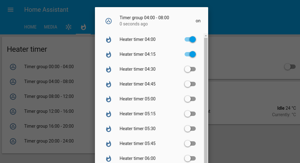
Do you remember the heater project in Home Assistant, published in the last issue of ODROID magazine? Well, maybe because I'm getting older, I feel the need to turn the heat on during certain hours of the day and night, so I wanted to create an app to do it for me. There's a catch though: I want to have some sort of user-friendly switchboard inside Home Assistant to allow me to select at what times I want the heater to be on, as some sort of cron job replacement. I estimated that having 15 minute intervals per switch should be fine, so, if I want to turn the heater on during 4:00 to 4:30, I would need to turn on two switches in the user interface (4:00 and 4:15).

A quick calculation shows us that a day consists of 96 15-minute intervals, and since I'm a lazy person and don't want to write all that configuration code, I made a script to generate the configuration for me (https://goo.gl/DYY5Mj). If you run the script above, it will create 96 input_boolean switches (https://goo.gl/BtJZ41), and distribute them into 4-hour groups. You can then copy/paste this into your configuration file under the relevant sections and restart Home Assistant. Don't forget to add the ‘heater_timer_group’ in the ‘heater’ view:

$ wget https://raw.githubusercontent.com/mad-ady/home-assistant-customizations/master/configuration_helper/make_heater_switches.py
$ python make_heater_switches.py

Configuration.yaml will look something like this:

input_boolean:
 …
 heater_timer_00_00:
 name: Heater timer 00:00
 initial: off
 icon: mdi:fire
 heater_timer_00_15:
 name: Heater timer 00:15
 initial: off
 icon: mdi:fire
 …

group:
 heater_timer_group_0:
 name: Timer group 00:00 - 04:00
 control: hidden
 entities:
 - input_boolean.heater_timer_00_00
 - input_boolean.heater_timer_00_15
 - input_boolean.heater_timer_00_30
 …
 heater_timer_group:
 name: Heater timer
 control: hidden
 entities:
 - group.heater_timer_group_0
 - group.heater_timer_group_1
 - group.heater_timer_group_2
 - group.heater_timer_group_3
 - group.heater_timer_group_4
 - group.heater_timer_group_5

…
 heater:
 name: Gas heater
 view: yes
 icon: mdi:fire
 entities:
 - switch.heater
 - climate.heater_thermostat
 - group.heater_timer_group

You should get the view shown in Figure 1 when done.

Figure 1 - Lots of timer switches

In order to give these switches functionality, there has to be some application to listen to their state changes in order to do the desired actions. I've written an code for AppDaemon which does the following:

  • On startup, it begins listening for events from input_boolean entities called heater_timer_*, which iterates through all entities and registers a listener for each one.
  • When it detects that a boolean has been toggled, it checks if the name of the boolean is the same as the current time, and if yes, controls the heater
  • Every minute that the corresponding input_boolean for the current time interval is checked. If it is on, then the heater is turned on.

The full source code is available at https://goo.gl/WGvoAL, and can be installed with the following commands:

$ cd ~homeassistant/.homeassistant/apps/
$ wget 
 https://raw.githubusercontent.com/mad-ady/home-assistant-customizations/master/appdaemon_apps/manual_heater.py

You will also need to edit the apps.yaml file and add the following:

manual_heater:
 module: manual_heater
 class: ManualHeater
 climate: "climate.heater_thermostat"
 heater: "switch.heater"
 interval_length: 15

Now, when you restart AppDaemon the new app will load and will react to the state of your input_booleans. You can follow its progress by reading the AppDaemon's log.

All might seem fine, however, there's a new problem. If you restart HomeAssistant, or if there's a power outage in the middle of the night, all 96 switches will default to the off position. There has to be a way to save their state and have them load the previous state on reboot. Luckily there already is an app for that: switch_reset.py, available at https://goo.gl/LVYdD2. Here's how you can configure it:

$ cd ~homeassistant/.homeassistant/apps/
$ wget -O switch_reset.py 
 https://raw.githubusercontent.com/home-assistant/appdaemon/dev/conf/example_apps/switch_reset.py
$ wget -O globals.py 
 https://raw.githubusercontent.com/home-assistant/appdaemon/dev/conf/example_apps/globals.py

Add the following configuration to apps.yaml:

switch_reset:
 module: switch_reset
 class: SwitchReset
 log: ""
 file: "/home/homeassistant/.homeassistant/switch_states"
 delay: 10

After restarting AppDaemon, the changes to input_boolean, input_number, input_select and device_tracker entities will be stored inside /home/homeassistant/.homeassistant/switch_states, providing our switch state persistence.

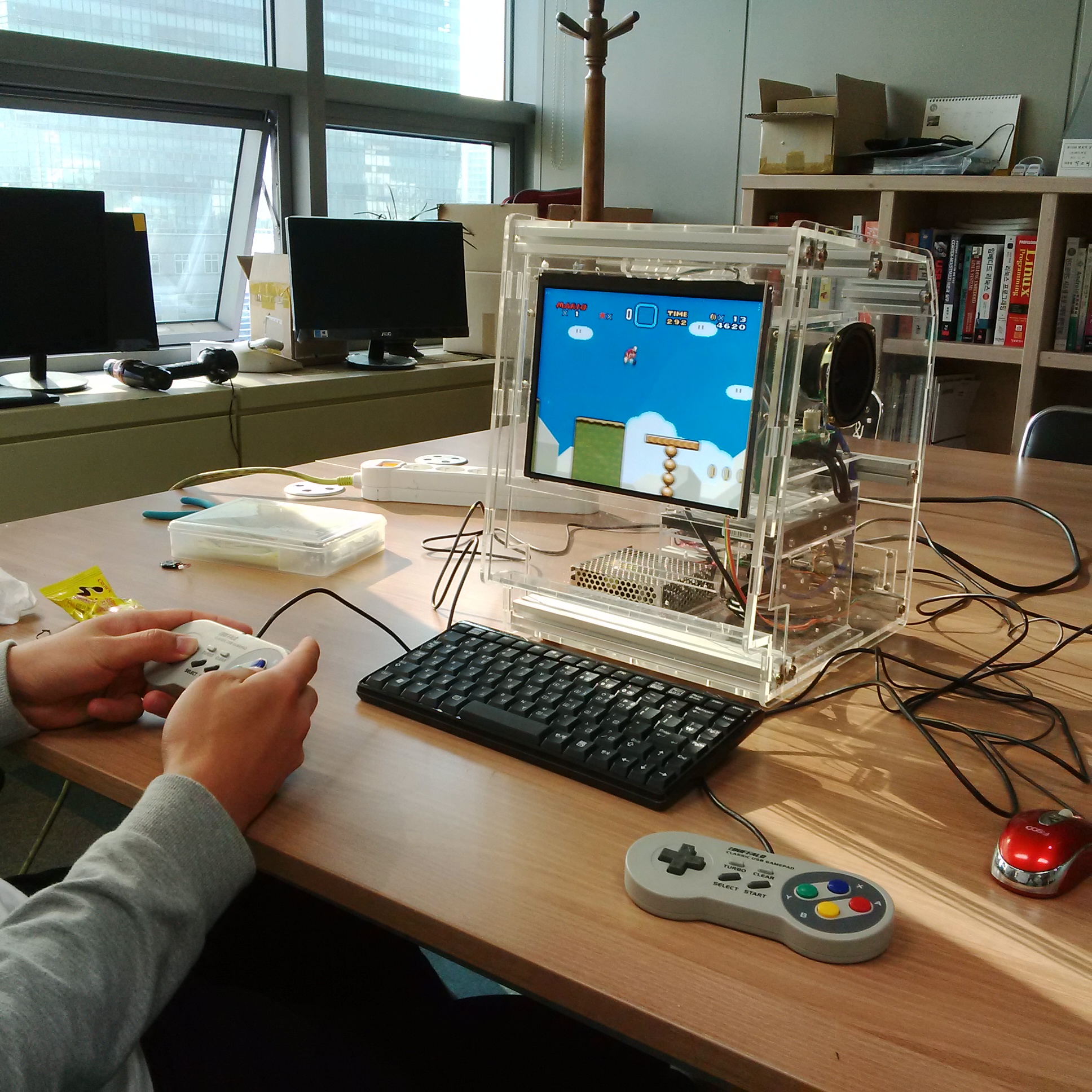
Although we’re using automated applications, the major reason why people use AppDaemon is because it provides a dashboard interface so that you can expose and control Home Assistant entities on a touchscreen. Usually people use a TV or a tablet to show the dasboard, but, I've used the HardKernel 3.5" LCD (http://www.hardkernel.com/main/products/prdt_info.php?g_code=G147435282441), with an ODROID-C2 as the computer backend.

Figure 2 - Example dashboard

In order to enable the dashboard (https://goo.gl/Z8iMW8), you will need to add the following section to appdaemon.yaml:

HADashboard:
 dash_url: http://0.0.0.0:5050
 dash_password: !secret api_password
 dash_dir: /home/homeassistant/.homeassistant/dashboards

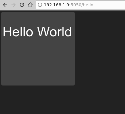
The dash_password directive is optional. For ease of use, it's best not to use a password, so that the dashboards can load on boot with no user intervention. You will need to create a sample dashboard under ~homeassistant/.homeassistant/dashboards. Create the directory first, then name it hello.dash:

$ mkdir ~homeassistant/.homeassistant/dashboards
$ mkdir -p 
 /home/homeassistant/.homeassistant/compiled/javascript/css
$ mkdir -p /home/homeassistant/.homeassistant/compiled/css
$ mkdir -p 
 /home/homeassistant/.homeassistant/compiled/html/default
$ cd ~homeassistant/.homeassistant/dashboards
$ vi hello.dash

hello.dash

#
# Main arguments, all optional
#
title: Hello Panel
widget_dimensions: [120, 120]
widget_margins: [5, 5]
columns: 8

label:
 widget_type: label
 text: Hello World

layout:
 - label(2x2)

After restarting AppDaemon, you will be able to access this at http://[odroid-ip]:5050/hello, where [odroid-ip] is the IP address of the ODROID-C2.

Figure 3 - Hello from the other side

Dashboards are dynamically generate web pages which can render and control the states of Home Assistant entities. Most entities have corresponding snippets of dashboard configuration, which can control appearances. The reference documentation is available at https://goo.gl/G6iYib.

In order to get started, you need to specify the screen dimensions and think about how you want to divide the screen into widgets. Usually the screen is divided into x*y cells, and each cell has a fixed width and height. You have some flexibility because you can merge cells to create a bigger one, and you can also have empty cells or rows. The standard cell size is 120x120 pixels. Since the 3.5" display has a small resolution (480x320), we'll need to get creative and implement some sort of menu to jump between different dashboards. We will also use small cells, 38x38, with a 1 pixel margin and combine them together to create larger widgets when needed. Note that if you are using a large enough screen you can use, and should use, larger widget sizes to avoid layout issues.

Regarding navigation with a menu, HADashboard has a navigation widget which can be used to load a different dashboard. The plan is to create an 8-item vertical menu which will be imported in all dashboards for quick navigation, then populate the dashboards according to my needs with internal data from Home Assistant, sensors, switches, media players, cameras, and external data such as Netdata Dashboard graphs or online weather. One of the buttons can serve as a menu and load a different dashboard with more buttons, so you have a lot of options.

Here is an example dashboard head that I've duplicated on all dashboards:

#
# Main arguments, all optional
#
title: 3.5in LCD panel - 480x320 divided into 12x8 cells - Home
widget_dimensions: [38, 38]
widget_margins: [1, 1]
columns: 12
use_gass_icon: 1

In order to set up navigation, I've set up a list of "buttons" in a different file called ~homeassistant/.homeassistant/dashboards/navigation-definition.yaml, which is imported in all dashboards and looks like this, just a few items are shown to give you an idea:

home:
 widget_type: navigate
 dashboard: "lcd35-hq"
 icon_active: fa-home
 icon_inactive: fa-home
mpd:
 widget_type: navigate
 dashboard: "mpdkitchen"
 icon_active: fa-music
 icon_inactive: fa-music
tv:
 widget_type: navigate
 dashboard: "tv"
 icon_active: mdi-television-classic
 icon_inactive: mdi-television-classic
 icon_style: "font-size: 1.5em !important;"
 …

extendedmenu:
 widget_type: navigate
 dashboard: "extendedmenu"
 args:
 timeout: 10
 return: lcd35-hq
 icon_active: mdi-menu
 icon_inactive: mdi-menu

You can get a copy of the complete file at https://goo.gl/vwYD33. As you can see, most entries are navigation widgets which get a dashboard file name as a parameter and can have a custom icon or style. The "extendedmenu" item causes that dashboard to be loaded for 10 seconds, then the "lcd35-hq" dashboard is loaded, if there is no other action. This allows you to simulate a popup menu that goes away by itself.

The layout of the widgets on the page is done by creating a layout directive with the rows enumerated below it. For each cell in a row, you would write the widget name as defined in the dashboard, or imported files. Widget names may have their size appended to the name. In order to reuse the configuration as much as possible, you can also import external definitions from other dashboards, like the navigation snippet above. The following snippet is from the main dashboard:

layout:
 - include: navigation-definition
 - include: sensors
 - home, clock(4x4), weather(7x4)
 - mpd
 - webcams
 - tv
 - heating, sensorliving(2x4), sensorkids(2x4), heater(2x4), forecast(5x4)
 - cooling
 - blinds
 - extendedmenu

The leftmost items on the list are the navigation targets defined in the navigation-definition.yaml file. Unfortunately, since I wanted to have a vertical menu, I need to explicitly add them to each dashboard. If I had only a horizontal row, I could have done the layout inside the navigation-definition.yaml file.

The top row begins with a small "home" widget used to navigate back here, then a 4x4 clock widget and a 7x4 weather widget. The next row lists only "mpd", which is part of the menu. The rest of the row is occupied by the big clock and weather widgets, so no new items are appended. Using this logic you can get a mental image of how it's supposed to look. The rest of the items are defined in the dashboard and in the included sensors.yaml, like this:

clock:
 widget_type: clock
 time_format: 24hr
 show_seconds: 0
 time_style: "color: yellow; font-size: 40pt; font-weight: bold;"
 date_style: "font-size: 16pt; font-weight: bold;"

weather:
 widget_type: weather
 units: "°C"
 sub_style: "font-size: 110%; font-weight: bold;"
 main_style: "font-size: 75%; font-weight: bold;"
 unit_style: "font-size: 250%;"

forecast:
 widget_type: sensor
 title: Prognoza
 title_style: "font-size: 14pt;"
 text_style: "font-size: 16pt; font-weight: bold;"
 precision: 0
 entity: sensor.dark_sky_forecast_ro

As you can see, most widgets require an entity which provides the glue to Home Assistant items, a type and the rest of configuration deals with fonts, colors and icons. The icons of various widgets can come from Home Assistant, but can be overridden with icons from Material Design, https://materialdesignicons.com, prefixed with mdi, or from Font Awesome,http://fontawesome.io, prefixed with fa.

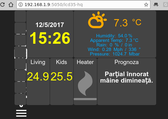
If you were to load this dashboard right now in a browser by navigating to http://odroid-ip:5050/lcd35-hq, it would look like Figure 4.

Figure 4 - Dashboard with broken navigation

However, there seems to be a problem with the layout of the navigation widgets. If you were to use Developer Tools in your browser and inspect the layout, you'd see that while the widgets are placed correctly, the icons inherit a CSS style which uses absolute positioning to offset the icon by 43 pixels downward. This is a problem because the dashboard was designed for larger displays with bigger widgets. In order to get around the issue, it's best if we create a skin that loads a custom javascript file that resets the absolute layout of icons and also adjusts the size. In order to do this, you'll need some Javascript, HTML and CSS know-how, but you can get the finished skin from at https://goo.gl/Fwcbti.

$ sudo su - homeassistant
$ cd .homeassistant/
$ mkdir -p custom_css/defaultsmall
$ cd custom_css/defaultsmall
$ wget -O dashboard.css 
 https://raw.githubusercontent.com/mad-ady/home-assistant-customizations/master/appdaemon_skins/defaultsmall/dashboard.css
$ wget -O dashboardsmall.js 
 https://raw.githubusercontent.com/mad-ady/home-assistant-customizations/master/appdaemon_skins/defaultsmall/dashboardsmall.js
$ wget -O variables.yaml 
 https://github.com/mad-ady/home-assistant-customizations/blob/master/appdaemon_skins/defaultsmall/variables.yaml

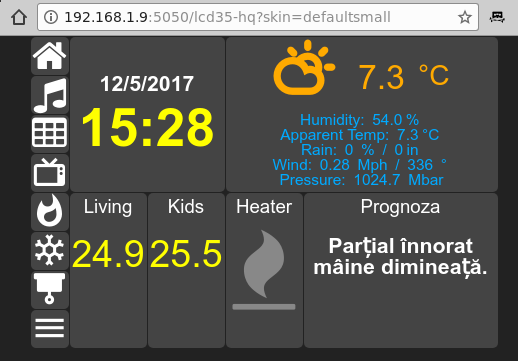
Now, if you reload the dashboard and specify an explicit skin you'll get much better results (http://[odroid-ip]:5050/lcd35-hq?skin=defaultsmall)

Figure 5 - Dashboard with navigation

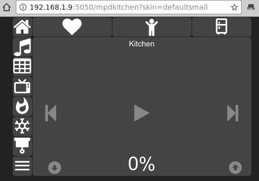
Now you can take a look at my dashboards. All the configuration is at https://goo.gl/VuB9sr. The MPD dashboard consists of 3 similar dashboards that I can cycle through by using the top navigate widgets. They load 3 different MPD instances around the house. The difference between the dashboards are just the instance loaded (see mpdkitchen below). The dashboard's layout is pretty simple:

layout:
 - include: navigation-definition
 - include: mpd
 - home, navigationmpdliving(4x1), navigationmpdkids(4x1), navigationmpdkitchen(3x1)
 - mpd, mpdkitchen(11x7)
 - webcams
 - tv
 - heating
 - cooling
 - blinds
 - extendedmenu
Figure 6 - Three MPD instances

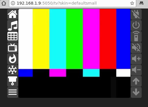
I also have a dashboard view to control my TV, which was imported in Home Assistant as described at https://magazine.odroid.com/article/home-assistantscripts-customization/. We are getting the image from a camera component inside Home Assistant and using the Camera Widget. The buttons are used to control the virtual remote and connect to script components in Home Assistant as well as to the script entity in HADashboard. An example for layout and widgets can be found below:

layout:
 - include: navigation-definition
 - home, streamtv(10x8), tv_living_off
 - mpd, tv_living_on
 - webcams, tv_living_source
 - tv, tv_living_mute
 - heating, tv_living_volume_up
 - cooling, tv_living_volume_down
 - blinds, tv_living_ch_up
 - extendedmenu, tv_living_ch_down

streamtv:
 widget_type: camera
 entity_picture: http://192.168.1.4:8123/api/camera_proxy/camera.tv_living_image?token=62f78994c790a89459e2f60cc6ed80bdfce3e9b5ff5473633ba60e3d7089f0a6&api_password=odroid
 refresh: 2

tv_living_off:
 widget_type: script
 entity: script.tv_living_power_off
 icon_on: mdi-power-plug-off
 icon_off: mdi-power-plug-off

tv_living_on:
 widget_type: script
 entity: script.tv_living_power_on
 icon_on: mdi-power
 icon_off: mdi-power

What's different about the camera widget is that it requires a URL via Home Assistant's API. This URL has to include the API key and also a token which is visible in Home Assistant -> Entities view for the entity in question. If you also use a password to access Home Assistant, you'll need to append the password to the URL. Figure 7 shows you the end result.

Figure 7 - Dashboard to monitor the TV

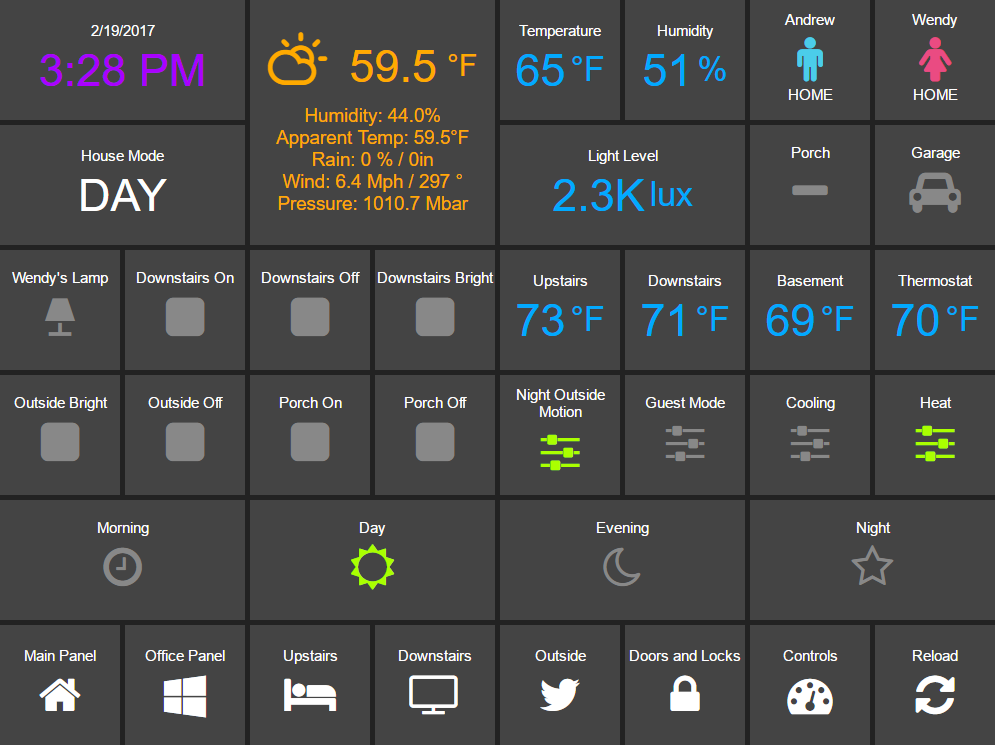
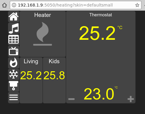
Another dashboard allows you to control the heater, manually, and the thermostat. The configuration for the thermostat widget looks like this, and the end result is in Figure 8.

layout:
 - include: navigation-definition
 - include: sensors
 - home, heater(4x4), thermostat(6x8)
 - mpd
 - webcams
 - tv
 - heating, sensorliving(2x4), sensorkids(2x4)
 - cooling
 - blinds
 - extendedmenu

thermostat:
 widget_type: climate
 title: Thermostat
 step: 0.5
 precision: 1
 entity: climate.heater_thermostat
 unit_style: "color: yellow;"
 level_style: "color: yellow; font-size: 48pt;"
 unit2_style: "color: yellow;"
 level2_style: "color: yellow; font-size: 40pt;"
 level_up_style: "font-size: 20pt;"
 level_down_style: "font-size: 20pt;"
Figure 8 - Heater dashboard

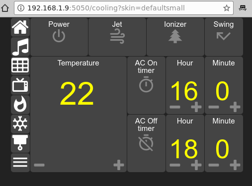
During the summer, the Cooling dashboard will see some use. Here are placed the sensors, switches and timers that control the AC system, as described in https://magazine.odroid.com/article/home-assistantscripts-customization/ . The dashboard looks like Figure 9.

Figure 9 - AC control

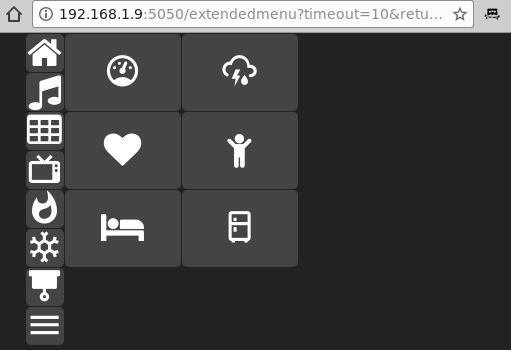
The extended menu is nothing more than a dashboard with more navigate widgets. In it, I have links to a Netdata dashboard and an Hourly forecast and images from my webcams, with room for more in the future.
The Hourly Weather forecast dashboard makes use of the iframe widget to load a URL, while the Netdata Dashboard cycles through a list of URLs every 5 seconds:

mynetdata:
 widget_type: iframe
 refresh: 5
 url_list:
 - http://192.168.1.5:19999/server1.html
 - http://192.168.1.5:19999/server2.html
 - http://192.168.1.5:19999/server3.html
 - http://192.168.1.5:19999/server4.html
 - http://192.168.1.5:19999/server5.html
Figure 10 - Extended menu

Now that the dashboard is working to your liking, you'll have to invest a bit of time on the display side. You can start with @FourDee's installation script for the display at https://forum.odroid.com/viewtopic.php?t=24248. You will also need to enable autologin inside lightdm (https://wiki.odroid.com/accessory/display/3.5inch_lcd_shield/autox#auto_login). Once this is done, it's time for some cleanup. It's best to remove programs that display popups on screen, like the Update Manager and screensaver:

$ sudo apt-get remove update-manager gnome-screensaver

We will also prepare a script that runs Chromium in Kiosk mode, with no password store, so that it won't ask you every time to unlock your password store. Chromium will also be set up with a fix that makes it forget it crashed, so in case of an unclean shutdown, it won't ask you if you want to restore the previous session. In addition to this, we'll set the monitor to always on:

$ cat /usr/local/bin/kiosk-mode.sh
#!/bin/bash
/usr/bin/xset s off
/usr/bin/xset -dpms
/usr/bin/xset s noblank
/bin/sed -i 's/"exited_cleanly": false/"exited_cleanly": true/' ~/.config/chromium/Default/Preferences
dashboard=lcd35-hq
/usr/bin/chromium-browser --noerrdialogs --incognito --password-store=basic --kiosk http://odroid-ip:5050/$dashboard?skin=defaultsmall
$ sudo chmod a+x /usr/local/bin/kiosk-mode.sh

You can also add the Scrollbar Anywhere Chrome extension (https://goo.gl/UD3hDA). Configure it to react to the left button and enable "Use Grab-and-drag style scrolling" so that you can scroll, if needed, with your finger on the dashboard.

Test that the script is working correctly when started from the graphical environment, and when ready, you can add it to the list of autostarted applications in Control Center -> Personal -> Startup Applications. Just click “add”, use "Kiosk mode" for the name, and /usr/local/bin/kiosk-mode.sh as the command. Once you restart lightdm, you should see a full screen dashboard.

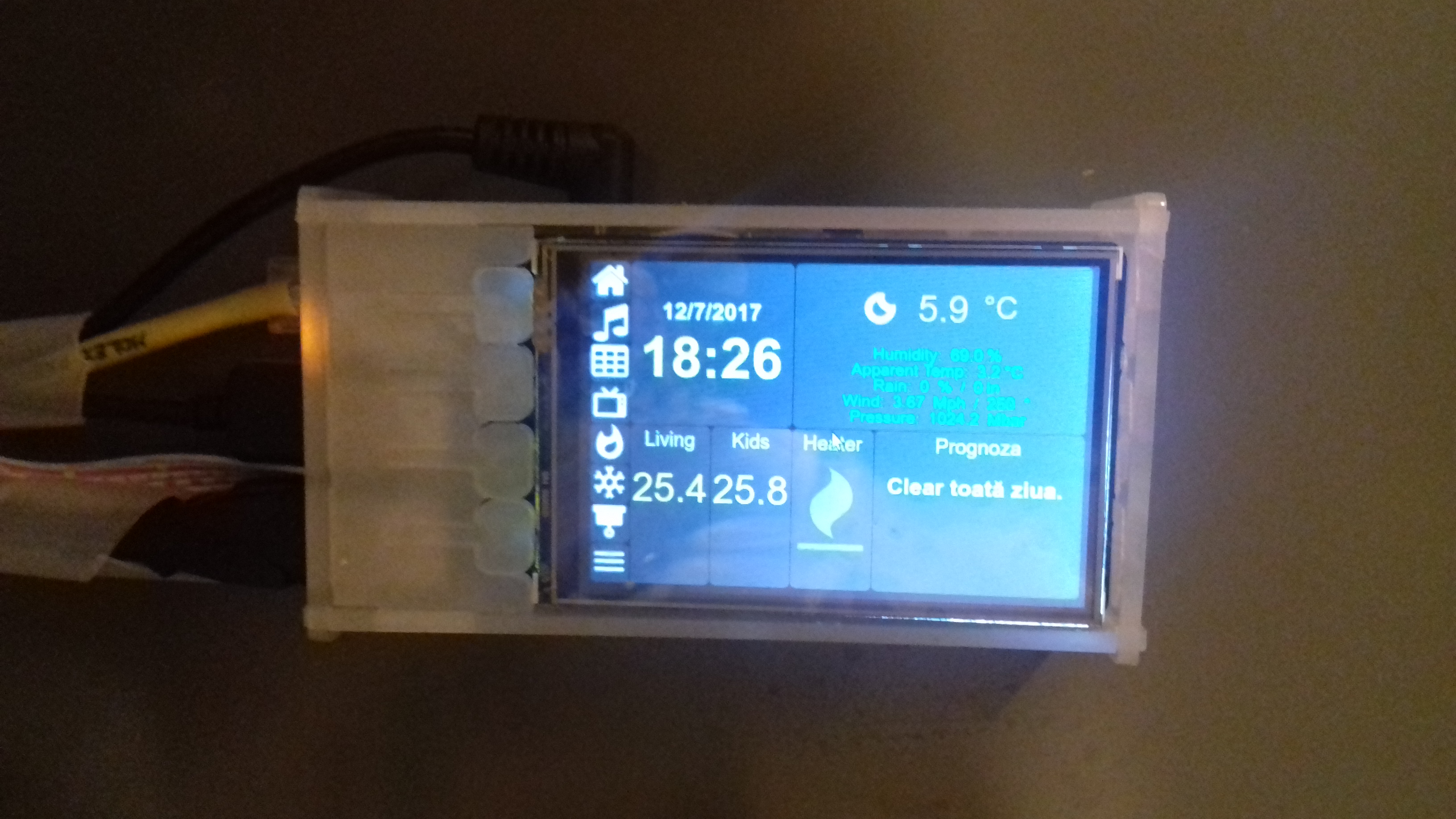
Show in Figure 11 is the end result, running on the 3.5" display. Hardkernel's 3.5" display is perfect for a small dashboard. The font sizes and colors used are optimized for easy reading from 2-3 meters away and the contrast helps with reading from wider angles. The display's low refresh rate of 10 fps is not noticeable with the dashboard.

Figure 11 - 3.5
Figure 11 - 3.5" display with the dashboard

You can get the dashboard configuration files from the GitHub project at https://github.com/mad-ady/home-assistant-customizations, and view a demonstration video at youtu.be/fEoHs3-_3B0. Please note that they were tested with appdaemon 2.1.12, but version 3 is currently under development ,and by the time you implement this, some things may have changed slightly. Keep an eye on the GitHub repository and on the support thread at https://forum.odroid.com/viewtopic.php?t=27321.

Orange eMMC Module: The Samsung 5.1 Chipset Arrives

Hardkernel has now introduced an orange eMMC module, which uses the Samsung eMMC 5.1 chipset, which has been shipping since October 2017.

Figure 1 - Hardkernel now offers an orange eMMC module)

It works with C1/C2/XU4 series with a proper OS. The latest official OS images all work fine. The schematics are available at eMMC PCB Rev 0.4. Orange eMMC compatibility status with XU4 series OS images

OS image Image file information Status
Ubuntu Mate ubuntu-16.04.3-4.14-mate-odroid-xu4-20171212.img OK
Ubuntu Minimal ubuntu-16.04.3-4.14-minimal-odroid-xu4-20171213.img OK
Android 7.1.1 Alpha-1.1_14.11.17 OK
Android TV 7.1.1 Alpha-1.0_20.11.17 OK
Android 4.4.4 Android 4.4.4 (v5.8) OK
Debian Jessie Debian-Jessie-1.1.4-20171121-XU3+XU4.img OK
ODROID Game Station Turbo (OGST) ODROID-GameStation-Turbo-3.9.5-20171115-XU3+XU4-Jessie.img OK
Armbian All Armbian variants starting with version 5.35 OK
OMV OMV_3_0_92_Odroidxu4_4.9.61 OK
DietPi DietPi_OdroidXU4-armv7-(Jessie).7z 22-Nov-2017 OK
Yocto project No Flashable file reference Untested
Kali-Linux No Flashable file reference Untested
Arch-Linux No Flashable file reference Untested
ROS No Flashable file reference Untested
Lakka Lakka-OdroidXU3.arm-2.1-rc6.img.gz OK
Batocera batocera-5.12-xu4-20171214.img.gz OK
RecalBox recalbox (17.11.10.2) OK-ish?
RetroPie No Flashable file reference Untested

The eMMCs from Sandisk will be version up to 5.1 with slightly faster data transfer speed starting from July 20, 2017. As shown in Figure 2, the QR code is on the left side of the ver5.1 ​chipset while eMMC ver 5.0 has it on the right side.

Figure 2 - eMMC version 5.0 (left) has the QR code on the right side, and eMMC version 5.1 (right) has the QR code on the left side)

Kernel version 3.10 should have the following patches applied in order to make it work with XU4 series properly: Github, Github, Github.

Figure 3 - Chart of eMMC modules for current running products 2016

Figure 4 - eMMC modules for old products

References

eMMC module Revison 0.3 schematics Yellow eMMC Module Revision 0.4 schematics eMMC reader board schematics

  • eMMC board dimensions : 18.5mm x 13.5mm
  • Gap between the PCBs : 1.1mm (Height of assembled B2B connectors

The connector is made by LS-Mtron Korea. On the eMMC module, the GB042-34S-H10 (Socket-34pin) was used. On the host board, the GB042-34P-H10 (Plug-34pin) was used. The connector specification is here Information about Sandisk eMMC (iDisk Extreme) Information about Samsung eMMC Information about Essencore eMMC (8GB eMMC is used for XU4) Information about Toshiba eMMC

eMMC Read/Write test on ODROID-C2 HS400 mode (Unit : MByte/sec)

Samsung Toshiba Sandisk
8G Write 45.4 21.9 N/A
8G Read 113 148 N/A
16G Write 80.1 N/A 25.6
16G Read 126 N/A 153
32G Write 124 N/A 98.7
32G Read 125 N/A 153
64G Write 124 83.7 107
64G Read 124 153 153

Read/write command for the eMMC benchmark:

$ dd if=/dev/zero of=test.tmp oflag=direct bs=1M count=1024
$ dd if=test.tmp of=/dev/null iflag=direct bs=1M

ODROID-C2 + Black eMMC Performance Test of File I/O test conditions

  • Ubuntu 16.04
  • Kernel version : Linux odroid64 3.14.79-115
  • Test tool : iozone revision 3.429

iozone installation and performance test:

$ sudo apt install iozone3
$ iozone -e -I -a -s 100M -r 4k -r 16k -r 512k -r 1024k -r 16384k -i 0 -i 1 -i 2<
/* 8G */
random random
kB reclen write rewrite read reread read write
102400 4 9290 13582 13570 13568 11900 8787
102400 16 10934 15680 27511 27484 25976 7699
102400 512 14943 23761 42163 42121 41361 15122
102400 1024 15140 28564 41951 41915 41196 16743
102400 16384 16559 24001 42308 42267 42287 28604
/* 16G */
random random
kB reclen write rewrite read reread read write
102400 4 14602 14622 18102 17953 16768 14421
102400 16 49363 49279 52902 52808 47450 48389
102400 512 49779 49993 138268 138315 137171 48836
102400 1024 50005 49870 137522 137709 136958 49027
102400 16384 49861 50058 139358 139154 139299 50024
/* 32G */
random random
kB reclen write rewrite read reread read write
102400 4 14608 14670 18333 18343 17935 14624
102400 16 58393 66157 56412 56766 55744 56371
102400 512 80356 81074 136828 137132 137503 79224
102400 1024 80464 81036 137368 137278 136896 79191
102400 16384 80388 81070 139486 139612 139446 80560
/* 64G */
random random
kB reclen write rewrite read reread read write
102400 4 14240 14299 17619 17548 16012 14216
102400 16 49991 57484 53245 53405 50001 59302
102400 512 132316 135079 134154 134016 134208 129755
102400 1024 132476 134966 133753 133840 133677 130054
102400 16384 135772 139140 136133 136019 135821 135107
/* 128G */
random random
kB reclen write rewrite read reread read write
102400 4 14162 14152 18161 18184 17833 14200
102400 16 56527 64906 55057 55684 54492 66525
102400 512 131327 131444 137307 137040 137358 132500
102400 1024 131908 131896 137570 137495 136844 132365
102400 16384 136418 134070 139940 133304 121160 134002
The black eMMC module is made with the Samsung eMMC chipset. The red and blue (normal) eMMC module is made with Sandisk or Toshiba or AIO chipset. The ODROID-C1/C0/C1+/C2 devices works with the black and red eMMC modules. The ODROID-XU4/XU3/U3/X2/U2 devices do NOT work with black eMMC module.

New 8GB eMMC test on XU4 Ubuntu

The new 8GB eMMC red PCB for the ODROID-XU4 model is based on Essencore/AIO's eMMC 5.0 technology. Sequential speed with “dd” test:

  • dd write : 15.1 MB/s
  • dd read : 104 MB/s
  • Random access(IOPS) speed test with 4k block.
  • Random write : io=993228KB, bw=9928.2KB/s, iops=2482
  • Random read : io=1479.1MB, bw=15149KB/s, iops=3787

eMMC vs SD card performance comparison on C2 Android using a 16GB eMMC Black PCB and a 16GB UHS-1 SDHC Card (Sandisk SDSDQAD-016G UHS-I 50 OEM model), with a cleanly flashed Android 5.1 V2.8 image and installed GApps Pico package:

  • eMMC booting time from power on event : 18~20 seconds
  • SDHC booting time from power on event : 32~35 seconds

Check points for system software developers

Do not overwrite the hidden eMMC boot partition. If you have, visit How to recover the eMMC boot loader to fix it. The eMMC must be partitioned as follows:

  • FAT16 partition with UUID 6E35-5356 (boot)
  • EXT4 partition with UUID e139ce78-9841-40fe-8823-96a304a09859 (Linux)

Copy the contents from Ubuntu image partitions to the boot and Linux partitions using “cp -afpv source destination”, then insert the eMMC module and boot normally. For comments, questions, and suggestions, please visit the original Wiki page at https://wiki.odroid.com/accessory/emmc/reference_chart.

Rebuilding x86/amd64 Docker Images For An ARM Swarm

After following the recent articles about building a Docker swarm on ARM (https://goo.gl/2FjP8f) and (https://goo.gl/ZTXcp), I found myself wanting to spin up services, for which no ARM image was available, or no ARM image with a recent version was available. The alternatives are trinary: 1) do without the thing I want, 2) settle for an older version of the thing I want, or 3) figure out how to build the thing I want. I am a bit of a tinkerer, and I like to have at least a working knowledge of my tools, so I went with the third option. For the most part, this is a very straight-forward process, but every once in a while, you end up having to tweak some things. Do not be intimidated by that, because it is worth it, and not that difficult of a journey. To help with this, let us set up a graphite stack. For this stack I will need several elements, plus some support in the form of an internally hosted image registry.

A registry

We will be using an already created image for this at http://dockr.ly/2kmNgod. The registry provides a place to store your custom images and deploy from. It is a great staging ground before you push your final product up to https://hub.docker.com or whatever other registry you choose.

The registry front end is just a handy little service to have going if you have a registry (http://dockr.ly/2D5DRt3). We will not go into the advanced features like deleting images, which requires additional setup on the registry side, but we will be able to browse our images and get information about them.

I'll be using go-carbon for the cache (https://goo.gl/hgjGZo). The choice was a simple one, since go-carbon will use more than one core in a single instance. It is really easy to setup, and if you have any schema definitions it may work just fine, and it also supports pickle format.

I will be using graphite-api for the render API endpoint https://goo.gl/P43pHC. There are other choices like carbonserverand carbonzipper. I believe go-carbon has support for carbonserver now, but I have not yet tried it. I think going the stock way is not so bad in this instance. It is only occasionally queried, so it does not need to be as high performance as the cache.

I will be using grafana for the display UI, since it is pretty standard (https://grafana.com). We could use the graphite-web package, but the graphing capabilities, while being the same, are much less accessible than grafana's. There are other options as well, and you should check them out before making any final decisions about what is right for you.

Deploy the infrastructure

Since the point of the swarm is really high availability and load balancing of those services (both hardware and network balancing), the services listed above will be launched as separate services. Please note that there are multiple options for each of these, but covering them is beyond the scope of this article. Having said that, let us get our infrastructure needs met, and deploy our registry:

$ docker service create --name=docker-registry --publish=5000:5000/tcp cblomart/rpi-registry
After this command completes, we have a registry. However, we have a problem that none of our Docker instances will use it because it is not secure. There are two approaches: the first is to configure your docker instances to use an insecure registry (specifically whitelisted), and the second is to get a certificate (self signed, or publicly verifiable). This is an internal registry. To get things moving along, I have chosen the first option. To do so on all of the docker nodes, add the following to /etc/docker/daemon.json, which assumes you have a default setup, and that this is the entire file:
{
    "insecure-registries": ["10.0.0.15:5000"]
}

Docker Registry UI

Now let us move to get the registry frontend in place, which will let us build our first image. Note that I used the hostname swarm. This is accurate in my setup, since I have a CNAME record in my DNS server, although your setup may be different:

$ git clone https://github.com/parabuzzle/craneoperator.git
$ cd craneoperator
$ docker build -t docker-registry-ui .
$ docker tag docker-registry-ui swarm:5000/docker-registry-ui-arm
$ docker push swarm:5000/docker-registry-ui-arm
Now we can launch our service. This one, like many others, makes use of environment variables to influence its operation. You will, of course, need to edit these to taste:
$ docker service create --name=docker-registry-ui --publish=8081:80/tcp -e REGISTRY_HOST=swarm -e REGISTRY_PROTOCOL=http -e SSL_VERIFY=false swarm:5000/docker-registry-ui-arm

Carbon cache and render API

Go-carbon is a Go application, and it requires Go 1.8+. So that we do not introduce any unnecessary issues by relying on a recent version of Go being available in my favorite package manager, we will just drop the latest version into a custom location. At the time of this writing, Go 1.9.2 is the latest version, so we will use that. I am also assuming you are running Linux, on an ARM machine, such as an ODROID-XU4, which makes a wonderful workstation. I drive each of my 3 monitors with an XU4, and use x2x to allow keyboard and mouse sharing, but that is an article for another time.

$ cd ~
$ mkdir -p ~/.golang/path
$ wget https://redirector.gvt1.com/edgedl/go/go1.9.2.linux-armv6l.tar.gz
$ tar -zxf go1.9.2.linux-armv6l.tar.gz
$ mv go .golang/root
$ export GOROOT=${HOME}/.golang/root
$ export GOPATH=${HOME}/.golang/path
$ export PATH=${GOROOT}/bin:${GOPATH}/bin:${PATH}
Now we are ready to start working on go-carbon. This one is nice, since it has a Dockerfile already made, and all we have to do is build the binary and set up our config files. Fetching the source, and building the binary can be done in one fell swoop:
$ go get -v github.com/lomik/go-carbon
Now that we have that out of the way, let us go set about building our Docker image:
$ cd ${GOPATH}/src/github.com/lomik/go-carbon
$ cp ${GOPATH}/bin/go-carbon .
$ mkdir config-examples
We will go ahead and stop here, since we are going to need to tweak the config file. There are a fair number of options, but you likely will not need any. I will leave it up to you to deal with any customizations and just assume that the defaults are good enough for now. The only edit we will make is to point to the correct schemas file and our data directory we can do this with a simple sed command:
$ ./go-carbon -config-print-default | sed -E 's,(schemas-file =).*, "/data/graphite/go-carbon-schemas.conf",g' | sed -E 's,(data-dir =).*, "/data/graphite/whisper",' > ./conf-examples/go-carbon.conf
Next, we can get our schemas file in order at /conf-examples/go-carbon-schemas.conf:
[default]
pattern = .*
retentions = 10s:1h, 30s:3h, 60s:6h, 1h:1d, 6h:1w, 12h:1m, 24h:1y
This gives us plenty of space for our metrics to aggregate and stick around for historical reasons. At this point, we are ready to start building our Docker image. I assume for the purposes of this article that this is the same machine you built go-carbon on and that it has Docker installed.
$ docker build -t go-carbon . && 
$ docker tag go-carbon swarm:5000/go-carbon-arm && 
$ docker push swarm:5000/go-carbon-arm
Now we can publish our service to our swarm. We have already done this a few times, so it should be familiar:
$ docker service create --name=carbon-cache --publish=2003:2003/tcp --publish=2003:2003/udp swarm:5000/go-carbon-arm
However, now we hit another snag. We need graphite-api installed into the image, because it needs access to the whisper files. You could create a shared filesystem and mount it for both the cache and the api images, but for the purposes of instruction, I think we will just modify our go-carbon image to support both. The first thing to note is the docker image is called “busybox”. Since I need Python, I chose to move this to 'debian:stretch'. The first thing is to get our graphite-api.yaml ready, which resides at ./conf-examples/graphite-api.yaml:
search_index: /data/graphite/index
finders:
  - graphite_api.finders.whisper.WhisperFinder
functions:
  - graphite_api.functions.SeriesFunctions
  - graphite_api.functions.PieFunctions
whisper:
  directories:
    - /data/graphite/whisper
Since we are starting more than one service, we should use a custom entrypoint script. Let us go ahead and write that now.
#!/bin/sh
gunicorn -b 0.0.0.0:8000 -w 2 graphite_api.app:app &
sleep 2
/go-carbon -config /data/graphite/go-carbon.conf
After moving over to debian:stretch and installing our packages and config, our Dockerfile in our go-carbon directory should now look something like this:
FROM debian:stretch
RUN mkdir -p /data/graphite/whisper/
RUN apt update && apt upgrade -y && apt dist-upgrade -y && apt autoremove -y
RUN apt install -y gunicorn graphite-api
ADD go-carbon /
ADD entrypoint.sh /
ADD conf-examples/* /data/graphite/
RUN chmod +x /entrypoint.sh
RUN rm /etc/graphite-api.y* ; ln -s /data/graphite/graphite-api.yaml /etc/graphite-api.yaml
CMD ["/entrypoint.sh"]
EXPOSE 2003 2004 7002 7007 2003/udp 8000
VOLUME /data/graphite/
Let us go ahead and rebuild, then push our new image:
$ docker build -t go-carbon . && 
$ docker tag go-carbon swarm:5000/carbon-cache-arm && 
$ docker push swarm:5000/carbon-cache-arm
We will then remove our old service and recreate them. I am aware of the upgrade processes for running services, but I felt that a fair amount could be written on that subject alone, so i would leave it as-is.
$ docker service rm carbon-cach
$ docker service create --name=carbon-cache --publish=2003:2003/tcp --publish=2003:2003/udp --publish=8000:8000/tcp swarm:5000/go-carbon-arm

Graphite setup

At this point, we are ready for the final piece of the project, which is another image that we will need to rebuild. However, thanks to Docker's "fat manifests" or manifest lists, referencing "debian" will get you the appropriate image for your architecture. Almost all official builds are done this way, so you no longer need to go hunting down an image for the ARM architecture.

Hopefully, in my next article, we will explore setting up your own "fat manifests" in your private registry. This is very useful if you, like me, have mixed architectures like amd64 into your swarm and would like any of your services to be able to deploy to any of your nodes. So let us get started on the Grafanas image. I chose the image at https://goo.gl/pfpVef, since it has all of the plugins you could want already loaded, and that saves a bunch of work for everyone. You can, of course, grab the official image and go through the same process:

$ git clone https://github.com/monitoringartist/grafana-xxl.git
$ cd grafana-xxl
$ cp Dockerfile Dockerfile.arm
We need to change line 17 from:
$ curl https://s3-us-west-2.amazonaws.com/grafana-releases/release/grafana_${GRAFANA_VERSION}_amd64.deb > /tmp/grafana.deb && 
To the following:
$ curl https://github.com/fg2it/grafana-on-raspberry/releases/download/v${GRAFANA_VERSION}/grafana_${GRAFANA_VERSION}_armhf.deb > /tmp/grafana.deb && \
Then, line 20 needs to change from:
$ curl -L https://github.com/tianon/gosu/releases/download/1.10/gosu-amd64 > /usr/sbin/gosu && \
To this:
$ curl -L https://github.com/tianon/gosu/releases/download/1.10/gosu-armhf > /usr/sbin/gosu && \
Once that is done, we are ready to rebuild, push, and deploy our service. We will use those increasingly handy and familiar commands again:
$ docker build -t grafana-xxl-arm -f Dockerfile.arm .
$ docker tag grafana-xxl-arm swarm:5000/grafana-xxl-arm
$ docker push swarm:5000/grafana-xxl-arm
$ docker service create --name=grafana --publish=3000:3000/tcp swarm:5000/grafana-xxl-arm
The final step is to login to your grafana instance at http://swarm:3000/ with the default username and password of “admin” and “admin”. Once you have logged in, simply add http://swarm:8000/ as your default grafana data source, and you are ready to use Docker.

Android Gaming: Monument Valley, Hopscotch, Aqueducts

It is not always that we stray from the indie weird games for Android, but on the holidays the play store we were gifted with a great title, so without further ado, lets go to:

Monument Valley

I could ramble about this game so much, but the best description comes first from the play store description itself: "In Monument Valley, you will manipulate impossible architecture and guide a silent princess through a stunningly beautiful world. Monument Valley is a surreal exploration through fantastical architecture and impossible geometry. Guide the silent princess Ida through mysterious monuments, uncovering hidden paths, unfolding optical illusions and outsmarting the enigmatic Crow People."

Figure 1 - Monument Valley will capture you from the beginning, be advised
Figure 1 - Monument Valley will capture you from the beginning

This is a game that push your gaming experience as few do, use it with your best headphones, you will not regret having this game on your collection. A game that channels the spirit of M.C. Escher, and takes you into a quest that will only end with you finishing this amazing game, then taking the ODROID that you played with to shop i order to frame it with a plaque with the following phrase: "I played Monument Valley on this hardware" (buy another ODROID afterwards, of course)

Figure 2 - I mentioned in the article, but please use your headphones :)
Figure 2 - I mentioned in the article, but please use your headphones for maximum enjoyment

Monument Valley at Play Store

Hopscotch

After such magnificence that was Monument Valley, which game should we pursuit on our gaming quest? Everything seems so trivial, and pointless. It was so much easier when we were in school, where everything was simpler and we had so much fun. Can we capture this feeling? It just so happens that yes we can! Just plug your touchscreen to your ODROID, and install Hopscotch. I don't have much else to say about it besides: "prepare to have your device taken from you, but this time it is not the teacher, but anyone that wants to feel the bliss that you are having when you are playing this game".

After playing a bunch of this game, try it in reverse!

Hopscotch at Play Store

Aqueducts

Figure 4 - Aqueducts is so much fun in such a simple concept.

And finally for this edition of Android Gaming, another plumbing-style puzzle game: Aqueducts.  This game gives you the task of the most powerful telekinetic in existence as you move gigantic pieces that seems to be placed by some sort of angry delivery guy, or the least funded engineer project ever. But jokes aside, you are about to face a game that is very well crafted and makes a very common gaming trope into a enjoyable experience. Try it, you will have the best time.

Aqueducts at Play Store

Android TV: ODROID-C2 with Amazon Prime Video and Netflix

I have been using an ODROID-C2 with LibreELEC for quite a while, but was frustrated by the lack of Amazon Prime Video and Netflix support. I was also using a wireless keyboard/mouse to control it, which led to the disapproval from the spouse, so I wanted a proper TV remote control to control both the TV (power/volume) and the ODROID-C2.

Here is the procedure I followed. It assumes you are somewhat comfortable with Android, such as finding Apps, and Settings, and will require use of Linux via the Android Terminal Emulator.

This procedure is to install not only Kodi, but also Youtube TV, Amazon Prime Video, Netflix and some individual Channel Apps. It also helps with installing apps from the Google Playstore. Although Netflix would not install from the Playstore one can download the APK and install that. The Remote Control configuration took the most time, because I could not find a single online tutorial detailed the entire process. Hopefully this article will help others with that.

The first step is to install Android on a Flash Card. Android for C2 can be downloaded from https://goo.gl/cuLqSU. At the time of this article, v3.5 is the latest version, and that is what I used. Download the image, uncompress it and install it to the flash card using Etcher, which is available for many operatins systems, or win32diskimager, which runs on Microsoft Windows, or the Linux dd utility. More information may be found at https://goo.gl/RPyiwr.

Install the flash card into the ODROID-C2 plugged into a TV via HDMI along with a USB keyboard/mouse and power on. It takes a few minutes, but eventually you should end up with a shiny new Android system, and the mouse should allow you to navigate.

The first step after Android is running is to adjust the overscan on the screen. I found on my TV that all the edges were missing. I could not see the notification bar at the top and the soft-keys at the bottom were mostly truncated. This is easily fixed by using the "ODROID Utility" app. Through this utility you can set the resolution (the default "autodetect" also works for me), use the arrows to adjust overscan and turn off the blue LED, which blinks to distraction. After adjusting the settings in this app, you must click "Apply and Reboot", which will reboot the system.

The next step is to install Google Apps to get the Google Play store utility. Using the stock default browser, the Google Apps APK can be downloaded from http://opengapps.org/. On this page, I selected the following:

  • Platform: ARM
  • Android: 6.0
  • Variant: pico

Pico is the minimum collection. You can also try to install nano and micro. Although I did not install the Calendar and other apps on my TV box, I believe they will work.

Selecting Download will pull a ZIP file into the Download folder. This ZIP file needs to be treated as an Android Update, and hence is loaded using the same Odroid Utility App used to update the Overscan and Blue LED above. Run the Odroid Utility app, and click on the upper right corner (three dots). The menu present will have an option "Package install from storage" which is clicked. On the next page, choose "File Manager" and navigate to the Download folder where you will select the open_gapps ZIP file. You will be prompted to proceed, after which time the odroid will reboot and the Google Apps will be installed.

After the installation is complete, you can open the Google Play Store app and install the following:

  • Amazon Prime Video
  • Kodi
  • Chrome Browser
  • Pluto TV
  • VPN client (if desired...I use OpenVPN)

Although there are numerous video apps, not all of them are TV-friendly. Install them one by one and test them to ensure they work as expected. You can uninstall the apps that do not work.

By default the Android setting “Settings -> Security -> Untrusted Sources” is set to “Yes”. This is needed to install Netflix. Netflix was the one app that is not available on Google Play Store. However, Netflix has a help page with a link to their v4.16 version of the APK at https://goo.gl/22XXZi.

I downloaded that APK and installed it with FileManager. It runs well with the remote control. There are newer versions of the Netflix APKs available from https://goo.gl/tkDbkz. However, when I downloaded a couple of them, I found they were not remote-control friendly. It is unclear why.

Configuring the apps is the same on all platforms. My Kodi installation communicates with a MythTV backend on another server which does all the LiveTV recording and manages my Movie collection. Finding the MythTV PVR addon was a bit of a challenge in Krypton. It is already in Addons->My Addons, but in a disabled state.

Remote control

I use an ODROID-C2 TV box with some old TVs that I inherited, and the original remotes were lost long ago. However, I have lying around some old Dish Network 3.0 IR PVR remote controls. These can be had on Ebay for under $10. In my opinion these are good sturdy remotes with good tactile feel and enough buttons that I should be able to do what I need. They are also "programmable" in that they come with a list of TV and other Device Codes which cause them to emulate the other manufacturer's remotes.

It was pretty easy to find the code to control my old TV. Power, Volume Up, Volume Down and Mute are all I really need. I thought I wanted "Input select" to work so that I can change HDMI ports, but nothing I did could get that remote button to work. Fortunately, the ODROID-C2 is the only input device I have, so no switching is needed. If I ever add a second HDMI device, it will probably require a revisit to the research process, to find a viable solution.

The first source of frustration was finding a device code that would activate all the buttons with the right protocol. The ODROID-C2 uses the Amlogic S905 chip which contains an interface to the Infrared receiver. The Hardkernel Android OS install contains the "amremote" driver built into the kernel (i.e., not loaded as a module). As far as I can tell, the "amremote" driver only recognizes the NEC Infrared Protocol. IR codes in other protocols (R5/R6 or Sony) simply are ignored by the “amremote” driver. If you want to read more on Consumer IR, check out https://goo.gl/WLgtv9.

Armed with a list of a few hundred codes, I sought out a remote control device code that would send NEC codes for all the buttons. Frustration set in when I found that many devices supported in the Dish Network remote control would only send codes for a limited set of buttons. I had a really hard time finding one that would send codes on the 5 navigation buttons (up, down, left, right and center). Many codes would facilitate only 3 options (up/down/center or left/right/center), or 4 or 5 of the options. I finally found a Memorex DVD player (code 709) which offered all 5 navigation directions and all the number buttons on the remote. It would not send the '*', '#', Volume or Mute codes. The Volume and Mute codes are relegated to the TV code and so I can only control the TV Volume using the buttons, not the Android Volume.

Since the "number keys" are mostly useless for a TV box (except for channel numbers), I re-purposed them in the remote.conf to perform operations such as the Android Home, Android Volume Up/Down/Mute and Fast Forward/Reverse.

To understand how an incoming IR signal gets to the App correctly you need to realize that there are 3 separate signals involved:

  • the IR code as sent by the Remote
  • the Linux KEYCODE, and
  • the Android ACTION code

The trick is to map the incoming IR code to the correct Android ACTION code via a Linux KEYCODE, and this conversion is done by two separate files in Android:

/system/etc/remote.conf -- maps IR code to Linux KEYCODE
/system/usr/keylayout/Vendor_0001_Product_0001.kl -- maps Linux KEYCODE to Android ACTION
In my case, both of these files required manipulation, although I tried to limit the changes to the keylayout. To change these files, I used the Android Terminal Emulator app, which gets me a “bash” shell, and the “vi” editor. If you do not know to use the “vi” editor, you may be able to copy the files to /storage, use the FileManager App that is installed and edit using that, and then copy back to the /system location. Below I rely on “vi” and various Linux commands to get the job done.

The first task is to change /system filesystem from ReadOnly to ReadWrite so that we can update the files. Open the Android Terminal Emulator app and type:

$ su -
# mount -o remount,rw /system
The first command (su -) gives you SuperUser privileges. The first time you use it you will get a popup asking whether this app (Android Terminal Emulator) should always get this privilege. I answered “Yes” and made it permanent. It is assumed that all following commands will be done in with SuperUser privileges. If you leave Android Terminal Emulator and come back, you may need to run the 'su -' command, again.

The second command will change the /system filesystem from ReadOnly to ReadWrite. Next, we need to edit /system/etc/remote.conf to turn on Debugging. Debugging will allow us to determine what codes we are receiving. Change "debug_enable" from “0” to “1” with vi and activate with remotecfg:

# vi /system/etc/remote.conf
# remotecfg /system/etc/remote.conf
The file remote.conf is read by remotecfg which will parse the contents and then send the information to the amremote software in the Linux kernel. This is normally done once on boot as specified in /system/init.odroidc2.rc. It is convenient because we can make changes and then immediately activate them.

With debug_enable set to “1”, any remote sending an NEC protocol will be detected, and the amremote software will log errors to the system log. We will use “dmesg” to see that system log. Test the change now by using these commands:

$ dmesg -c > /dev/null # clear previous log contents
$ while sleep 1; do dmesg; dmesg -c > /dev/null; done
With the "while sleep" running pressing a button on the remote control should elicit something like this:
[98086.788285@0] remote: Wrong custom code is 0x7c83ff00
The last four digits of the number at the end of the log message tells us what what remote type this is (0xff00 in my case). The default remote.conf from Odroid Android looks for code 0x4db2. I am not sure what the odds are that you have a remote with that code if you are not using the Remote available from HardKernel (https://goo.gl/yVLVLC). If you are unlucky, and the remote you are using does transmit 0x4db2, then you will see something else in dmesg. If you see nothing in dmesg, then you are not using a remote that transmits NEC protocol and must find another remote (or device code).

In my case, this is where I started searching the Dish Network 3.0 IR device codes looking for a suitable device. I set the device code in the remote, and hit the buttons to see if I got responses in dmesg. I tried many many codes until I was close enough to my requirements with the Memorex DVD code 709, which transmits remote type 0xff00.

The long HEX number 0x7c83ff00 is actually 2 pieces of real info. Break it up in into bytes: 7c 83 ff 00, and you should notice that the first 2 bytes are ones complement of each other (ie 01111100 -> 10000011 -- zeros and ones flipped). Similarly, the 3rd/4th bytes are ones complement in many (but not all) cases. The "real" information is in bytes 2 and 3/4 (0x83 is the button, 0xff00 is the type of remote).

In remote.conf, it is now time to set the type of remote you are using in remote.conf by setting the entry for "factory_code" and replacing the XXXX with the 4 digit code found above (I set mine to 0xff000001):

$ vi remote.conf
$ remotecfg /system/etc/remote.conf
$ while sleep 1;do dmesg;dmesg -c > /dev/null;done
After these commands, you should again be able to press buttons and one of two things will happen: You will see an error indicating the remote button does not map to anything, or you will see information on what the button mapped to.
[101131.973324@0] remote: scancode is 0x00c5,invalid key is 0x0000.
or
[101214.803355@0] remote: press ircode = 0xc5
[101214.903456@0] remote: scancode = 0x74,maptable = 0,code:0x3ac5ff00
[101214.903492@0]
[101214.993555@0] remote: release ircode 0xc5
[101214.997312@0] remote: scancode = 0x74,maptable = 0,code:0x00000000
The first one occurs because the button 0xc5 is not in remote.cfg. The second one occurs when the button is found in remote.cfg. If the remote you are using sends codes similar to those of the Hardkernel remote, you may see the second type of message.

This is where the fun begins. You need to press every button and see what code it sends, and note that. Then you need to figure out what you want it to do and find the Android action in the Vendor_0001_Product_0001.kl file that corresponds to the action you want the button to do. Finally, you need to get the Linux KEYCODE from Vendor_0001_Product_0001.kl that will be used to tie everything together.

Configuration

These are the ANDROID actions that I am using:

  • POWER -- key 116
  • HOME -- key 102
  • BACK -- key 15
  • MENU -- key 139
  • DPAD_CENTER -- key 97
  • DPAD_LEFT 1 -- key 105
  • DPAD_RIGHT -- key 106
  • DPAD_UP -- key 103
  • DPAD_DOWN -- key 108
  • VOLUME_UP -- key 115
  • VOLUME_DOWN -- key 114
  • VOLUME_MUTE -- key 113
  • MEDIA_REWIND -- key 121
  • MEDIA_FAST_FORWARD -- key 120
  • APP_SWITCH -- NO KEY available!

The last one, "APP_SWITCH", is not in Vendor_0001_Product_0001.kl! It took me 2 hours to figure that one out. So I appropriated a key (158, which was formerly BACK) by updating Vendor_0001_Product_0001.kl with vi and changing "BACK" to "APP_SWITCH" on the appropriate line.

Now glue everything together by updating remote.conf in the key_begin/key_end section and possibly in the repeat_key_begin/repeat_key_end section. I do not rely on key repeats, so my repeat_key_begin/repeat_key_end section is empty. Also, I am not relying on the mouse_begin/mouse_end section either.

My resulting remote.conf file looks like:

work_mode = 0
repeat_enable = 1
repeat_delay = 40
repeat_period = 39
release_delay = 121
debug_enable = 0
factory_code = 0xff000001
left_key_scancode = 0x88
right_key_scancode = 0xc8
up_key_scancode = 0xc9
down_key_scancode = 0xd7
ok_key_scancode = 0x8b
mouse_begin
mouse_end
key_begin
0xc5 116 # Power
0x8b 97 # Center
0xc9 103 # Up
0xd7 108 # down
0x88 105 # Left
0xc8 106 # Right
0x93 15  # cancel
0x93 15  # Info
0x81 114   # 1 -- becomes VOLUME DOWN
0x83 113   # 2 -- becomes MUTE
0xc1 115   # 3 -- becomes VOLUME UP
0x82 121   # 4 -- becomes REWIND
0x80 139   # 5 -- becomes MENU
0xc0 120   # 6 -- becomes FF
0x8d 8     # 7
0x8f 158   # 8 -- APP SWITCH
0xcd 10  # 9
0x8c 102  # 0 -- becomes HOME
key_end
repeat_key_begin
repeat_key_end
Note that I also turned "debug_enable" off again by setting it to zero. After updating remote.conf again, type the following command:
$ remotecfg /system/etc/remote.conf
Now it is the time to test the remote. You want to test each app, since they can react differently to a particular code or ignore it completely. I am still not sure that I have all the keys where I want them, but the system is functional and usable.

Make a backup of Vendor_0001_Product_0001.kl and remote.conf by copying them to /storage/emulated/0/Download and make sure they are saved in the /system filesystem. If you upgrade Android, you may find that these files need restoration or your remote will not work anymore. Hope this is useful to at least one person. I will probably need to dig it up in the future so I can remember what I did. For comments, questions and suggestions, please visit the original forum post at https://goo.gl/6sc8GU.

Ambilight on the ODROID-C2 Using LibreElec: Adapting the Ambilight for the ODROID-C2

In this article, I’d like to share how I managed to build a working Ambilight system using an ODROID-C2 and LibreElec. Other guides I previously found mainly targeted the Raspberry Pi, so I had to collect the information using Google and a bit of trial and error.

The high-level design uses Hyperion installed as an add-on for Kodi, from the LibreElec repo-- installing by HyperCon is not possible due to the CPU for it being unknown--and an Arduino for controlling the LEDs using the FastLED library. The Arduino is connected to the ODROID-C2 via USB cable (the Arduino contains an USB-to-Serial converter). My TV is FullHD, so I needed no magic (i.e. RAM overclock and stuff like this) for 4K.

I used the below guides as a base for assembling and configuration. But since these guides are aimed toward use with the Raspberry Pi, I needed to adapt for ODROID-C2.

Raspberry Pi 3 Mediacenter + Hyperion Ambilight + NO soldering: https://goo.gl/q8q6PK Amblight project/guide - Hyperion - WS2801/ WS2812B / APA102: https://goo.gl/CEgT1U

It turns out that my configuration is affected by the rather annoying bug described here: https://goo.gl/HUwa2k

Video playback of starts to slow down after an arbitrary amount of time (between 30-70 minutes in my case) while the audio continues to play at proper speed, causing the audio and video to go out of sync with each other. After 30-60 seconds there is a small pause and skip, then afterwards the audio and video are in sync again, until it happens again in 30-70 minutes.

The above topic in the LibreElec forum is still unresolved, as the issue is proving quite difficult to fix. If anyone has a working system (ODROID-C2 running LE 8/Kodi 17 with Hyperion) that is not affected by this bug, please feel free to contribute the Hyperion config file! I plan to fiddle with Hyperion settings to see if something makes a difference, but that may take quite a bit of time.

Hardware

  • ODROID-C2 plus case and power supply from Hardkernel, which cost about €72 when I bought it from https://www.pollin.de last year
  • Kingston 16GB Class10 MicroSD card, which cost about €8 from eBay
  • Chinese clone of the Arduino Uno R3 board plus case and USB cable, which cost about €8.50 from eBay
  • WS2812B 3-pin RGB LED strip, 30 LEDs per meter, 5m roll, which cost about €13.50 from eBay
  • 5V 10A power supply. I had one laying around, so there was no cost, but you could probably find one for €10-20 on eBay or Aliexpress
  • DIN power plug, which cost about €1.50 from eBay
  • 3-pin JST male and female connector cables, which cost about €1.50 from eBay for 5 pieces
  • 3-pin connectors 10mm for WS2812 set, which cost about €2 from eBay for 5 pieces
  • Dupont male jumper cables, which cost about €1 from eBay for 40 pieces
  • Heat shrink tubes, which cost about €EUR 1 from eBay for 70 pieces
  • 500 ohm resistor, or 2 x 1K ohm resistors wired in parallel
  • HDMI cable
  • Electric welder for soldering the plugs and cables

Software

  • LibreElec 8.2.1 MR image for ODROID-C2 downloaded from https://libreelec.tv
  • Hyperion AddOn for Kodi from LibreElec repo
  • HyperCon tool for Hyperion (https://goo.gl/7F5fDc)
  • Arduino IDE (https://goo.gl/wqP28G)
  • FastLED library for Arduino (download ZIP - https://github.com/FastLED/FastLED)
  • Control sketch (script) for Arduino (https://pastebin.com/2L9ZBhYe)

 
#include "FastLED.h"

// How many leds in your strip?
#define NUM_LEDS 92

// For led chips like Neopixels, which have a data line, ground, and power, you just
// need to define DATA_PIN. For led chipsets that are SPI based (four wires - data, clock,
// ground, and power), like the LPD8806 define both DATA_PIN and CLOCK_PIN
#define DATA_PIN 12
//#define CLOCK_PIN 13

#define COLOR_ORDER GRB

// Adalight sends a "Magic Word" (defined in /etc/boblight.conf) before sending the pixel data
uint8_t prefix[] = {'A', 'd', 'a'}, hi, lo, chk, i;

// Baudrate, higher rate allows faster refresh rate and more LEDs (defined in /etc/boblight.conf)
#define serialRate 115200

// Define the array of leds
CRGB leds[NUM_LEDS];

void setup() {
 // Uncomment/edit one of the following lines for your leds arrangement.
 // FastLED.addLeds<TM1803, DATA_PIN, RGB>(leds, NUM_LEDS);
 // FastLED.addLeds<TM1804, DATA_PIN, RGB>(leds, NUM_LEDS);
 // FastLED.addLeds<TM1809, DATA_PIN, RGB>(leds, NUM_LEDS);
 // FastLED.addLeds<WS2811, DATA_PIN, RGB>(leds, NUM_LEDS);
 // FastLED.addLeds<WS2812, DATA_PIN, RGB>(leds, NUM_LEDS);
 FastLED.addLeds<WS2812B, DATA_PIN, RGB>(leds, NUM_LEDS);
 // FastLED.addLeds<NEOPIXEL, DATA_PIN>(leds, NUM_LEDS);
 // FastLED.addLeds<UCS1903, DATA_PIN, RGB>(leds, NUM_LEDS);
 // FastLED.addLeds<UCS1903B, DATA_PIN, RGB>(leds, NUM_LEDS);
 // FastLED.addLeds<GW6205, DATA_PIN, RGB>(leds, NUM_LEDS);
 // FastLED.addLeds<GW6205_400, DATA_PIN, RGB>(leds, NUM_LEDS);

 // FastLED.addLeds<WS2801, RGB>(leds, NUM_LEDS);
 // FastLED.addLeds<SM16716, RGB>(leds, NUM_LEDS);
 // FastLED.addLeds<LPD8806, RGB>(leds, NUM_LEDS);

 // FastLED.addLeds<WS2801, DATA_PIN, CLOCK_PIN, RGB>(leds, NUM_LEDS);
 // FastLED.addLeds<SM16716, DATA_PIN, CLOCK_PIN, RGB>(leds, NUM_LEDS);
 // FastLED.addLeds<LPD8806, DATA_PIN, CLOCK_PIN, RGB>(leds, NUM_LEDS);

 // initial RGB flash
 LEDS.showColor(CRGB(255, 0, 0));
 delay(500);
 LEDS.showColor(CRGB(0, 255, 0));
 delay(500);
 LEDS.showColor(CRGB(0, 0, 255));
 delay(500);
 LEDS.showColor(CRGB(0, 0, 0));

 Serial.begin(serialRate);
 Serial.print("Ada
"); // Send "Magic Word" string to host
}

void loop() {
 // wait for first byte of Magic Word
 for(i = 0; i < sizeof prefix; ++i) {
 waitLoop: while (!Serial.available()) ;;
 // Check next byte in Magic Word
 if(prefix[i] == Serial.read()) continue;
 // otherwise, start over
 i = 0;
 goto waitLoop;
}

// Hi, Lo, Checksum

while (!Serial.available()) ;;
 hi=Serial.read();
 while (!Serial.available()) ;;
 lo=Serial.read();
 while (!Serial.available()) ;;
 chk=Serial.read();

// if checksum does not match go back to wait
 if (chk != (hi ^ lo ^ 0x55))
 {
  i=0;
  goto waitLoop;
 }

memset(leds, 0, NUM_LEDS * sizeof(struct CRGB));
// read the transmission data and set LED values
for (uint8_t i = 0; i < NUM_LEDS; i++) { byte r, g, b; while(!Serial.available()); r = Serial.read(); while(!Serial.available()); g = Serial.read(); while(!Serial.available()); b = Serial.read(); leds[i].r = r; leds[i].g = g; leds[i].b = b; } // shows new values FastLED.show(); }

Assembling the LED strip

The LED strip I purchased already had a 3-pin JST female socket built to the starting end, plus two additional wires (without a socket) for 5V and GND. I soldered used the latter two wires to the DIN power plug so that I could power the LEDs from the power supply. Make sure to use a plug that is compatible with your power supply!

I took a male JST connector cable and soldered Dupont wires to the end of GND and DATA wires so I could plug them into the pinouts of the Arduino board. The 5V wire is not used here, since it is not connected, so it can be cut and/or insulated. I soldered the 500 ohm resistor between the DATA wire and the Dupont cable so that control signals could go through it. All solder-joints have been secured by heat shrink tubes.

I started HyperCon on my computer and planned the configuration and the LED layout on the TV, making sure to measure the dimensions of my TV. I explored other configuration options on the Hyperion Wiki site and saved the LED config to the hyperion.config.json file. I then used the calculated LED numbers to cut the strip into appropriately sized pieces and used the 3-pin connector cables to attach them to each other. The 3-pin connector cables are required for the corners of the TV as the LED strip alone cannot be bent for 90 degrees.

Please note that these LED strips have a direction. Only the starting end can be used for input controls and distinct LEDs are addressed following each other. Look for “DI (Data Input) marking on the strip, near the LEDs themselves. The other end has “DO (Data Out) marking. You can use Google to find the WS2812b specifications.

My experience is that the 3-pin connectors cannot hold the strip too tightly, so exercise caution when mounting it to the back of your TV. If you have experience in precision soldering, you may be better off soldering wires to connect the strip parts instead of using the 3-pin connectors.

I installed LibreElec onto the micro SD card as per the instructions on https://libreelec.tv, then assembled the ODROID-C2 and configured Kodi to my taste. I went to Settings -> Services -> Control in Kodi interface, and enabled both “Allow remote control from applications on this system” and “Allow remote control from applications on other systems”. I installed Arduino IDE to my computer, then extracted the FastLed library ZIP file to a separate subfolder under the libraries folder. When I started the Arduino IDE after this, the FastLED library became available under the Sketch -> Available libraries menu.

I attached the Arduino board to my computer using the USB cable. I copied the sketch into Arduino IDE, set the number of LEDs in the strip in row #4 (you will have this number from HyperCon), and the pin used for LED control in row #9. Then I uploaded the sketch into the Arduino board, which only took a few seconds.

Assembly

I used the adhesive on the back the LED strip to stick it to the back of my TV. Some extra adhesive was required in a few places in order for it to stick firmly. I unplugged the Arduino board from my PC and plugged it into one of the USB ports on the ODROID-C2. I plugged the Dupont cable jumper soldered to the GND wire of the strip to the GND pin and the Dupont cable jumper soldered to the DATA wire of the strip to pin 12 of the Arduino. Finally, I plugged the power supply into the power plug soldered to the end of the strip.

Software configuration

LibreElec loaded the CH341 module automatically upon connection of the Arduino board to USB, and device /dev/ttyUSB0 appeared. This might, however, be different for you. I installed the Hyperion add-on on the Kodi interface, from the LibreElec repo. I opened the previously saved hypercon.config.json file on my computer, and edited it in 3 locations: device, frame-grabber, and effects. Updating the effects folder is necessary because it is different when Hyperion is installed as an add-on, instead of installing by HyperCon.

Note that other guides state to use 100000, 200000, and so on for the baud rate. For me, this resulted a repeated “Unable to open RS232 device (IO Exception (25): Inappropriate ioctl for device” error message in the Hyperion log. Switching to a 115200 baud rate made the issue go away. Make sure to notice the reversed “GRB” color order!

// DEVICE CONFIGURATION
"device" :
 {
 "name" : "MyHyperionConfig",
 "type" : "adalight",
 "output" : "/dev/ttyUSB0",
 "rate" : 115200,
 "delayAfterConnect" : 0,
 "colorOrder" : "grb"
 },

"amlgrabber" :
 {
 "width" : 64,
 "height" : 64,
 "frequency_Hz" : 20.0,
 "priority" : 880
 },
 "framegrabber" :
 {
 "width" : 64,
 "height" : 64,
 "frequency_Hz" : 10.0,
 "priority" : 890
 },

"effects" :
 {
 "paths" :
 [
 "/storage/.kodi/addons/service.hyperion/effects"
 ]
 },
I uploaded my updated hyperion.config.json file to /storage/.kodi/userdata/addon_data/service.hyperion/ folder in LibreElec. This is the folder where the Hyperion add-on looks for the config file. The UserData share can be used for the upload if the SMB server is enabled. I then rebooted LibreElec and, the Ambilight system now works properly for me. Hopefully I haven’t forgot anything above and someone will make use of this information. Any comments or suggestions for improvement are welcome!

For comments, questions, and suggestions, please visit the original forum post at https://forum.odroid.com/viewtopic.php?f=144&t=29334.

Having Fun with GPIO on Android

The ODROID-C1/C1+, ODROID-C2, and ODROID-XU4 have on-board GPIO (General Purpose Input/Output) pins that allow the control of external devices through software. In order to access the GPIO port properly, you must install the Android Marshmallow version 2.8 image or higher on the ODROID-C2, the Android KitKat version 3.2 image or higher on the ODROID-C1/C1+, and either the Android KitKat version 6.0 image or higher, or the Android Nougat version 1.3 20171214 image or higher on the ODROID-XU4.

This WiKi explains how to make an Android app which can access GPIO ports. You need to install Google Android Studio on your host PC. Add NDK and tools first before starting below steps. We tested the following steps on Android Studio 2.3 and NDK R14.

Ubuntu/Linux

You can find the Android SDK location on this menu (File → Settings → Appearance & Behavior → System Settings → Android SDK)

Figure 1 - Android SDK location

After editing the bashrc file, you have to login again or type “source ~/.bashrc” on the command line. Then, download the WiringPi NDK library and App source code Project from GitHub.

ODROID-C1+/C2

$ sudo apt install git
$ git clone https://github.com/codewalkerster/example-wiringPi -b odroid-c

ODROID-XU4

$ sudo apt install git
$ git clone https://github.com/codewalkerster/example-wiringPi -b odroid-xu
Run Android Studio and open the downloaded project.

Figure 2 - Opening the wiringPi project

Build the project to make an apk package

Select Build -> Make Project from the menu. You will see a couple of error messages, and will need to click the following options to complete the build process, which will produce an APK file to run on your ODROID:

  • Install missing platform(s) and sync project
  • Install Build Tools 25.0.2 and sync project

Windows

In Window, set the environment PATH to point to the NDK folder path, then reboot Windows.

Figure 3 - Setting the environment path to point to the NDK folder path

Figure 4 - Setting the environment path to point to the NDK folder path

Figure 5 - Setting the environment path to point to the NDK folder path

Next, install the Git client program from https://git-for-windows.github.io/, and clone the wiringPi project, as shown in Figure 6.

Figure 6 - Cloning the project

The project is available at https://github.com/codewalkerster/example-wiringPi. Select origin/odroid-c or origin/odroid-xu.

Figure 7 - Checking out the GitHub branch

Then, install the NDK by selecting Tools -> Android -> SDK Manager from the menu.

Figure 8 - Installing the SDK

Figure 9 - Installing the SDK

Features of the example project

You can read the analog-to-digital converter (ADC) value and show the voltage level with 19 LEDs on the GPIO output. You can view a demo video at https://youtu.be/lGqyhvd3q9U and https://youtu.be/lGqyhvd3q9U.

Figure 10 - Reading the ADC value on the ODROID-C1+/C2

Figure 11 - Reading the ADC value on the ODROID-XU4

PWM

Figure 12 shows a basic PWM control example. You can choose the number of PWM outputs (1 or 2), as well as control the frequency and duty ratio.

Figure 12 - Basic PWM control example

Gmail Notifier example

This is a fun and useful project using the PWM port. When you are watching videos or playing games, you may miss notification of an important email or message. The flag is moved by servo motor which is connected to a PWM pin on 40pin GPIO port. The code may be downloaded from https://github.com/codewalkerster/GMailNotifier. A demo of the project may be viewed at https://youtu.be/Vvq77w87RWQ.

I2C

Figure 15 shows example code for accessing our Weather Board is available in order to measure the temperature, humidity, atmospheric pressure, altitude and visible/invisible light intensities via I2C interface.

Figure 13 - Hardkernel’s Weather Board measures environmental statistics

Figure 14 - Hardkernel’s Weather Board measures environmental statistics

Figure 15 - A demo software for Sending and Receiving characters via UART interface

Figure 16 - Demo software to access 1-wire protocol interfaced DS18S20 temperature sensor

Kernel for I2C

Open the File Manager app, and edit the file /storage/internal/boot.ini as shown below:

Original

movi read dtb 0 ${dtbaddr}
# load kernel from vat or boot partition.
movi read boot 0 ${loadaddr}
#fatload mmc 0:1 ${loadaddr} Image
booti ${loadaddr} - ${dtbaddr}
After edit
movi read dtb 0 ${dtbaddr}
# load kernel from vat or boot partition.
#movi read boot 0 ${loadaddr}
fatload mmc 0:1 ${loadaddr} Image
booti ${loadaddr} - ${dtbaddr}
Load the kernel image from the vfat partition built i2c. If you cannot find the “fatload” command, remove /storage/internal/boot.ini file and reboot the system. For comments, questions and suggestions, please visit the original Wiki article at https://wiki.odroid.com/odroid-c2/application_note/gpio/enhancement_40pins_on_android.

UART Daisy Chain: Expert Debugging With The ODROID-C2

UART Daisy Chain

This article explains how to use multiple UART ports on ODROID-C2 running the Android OS. We will use 3 UART ports and create a data flow called a Daisy Chain. The basic flow of data is out from TX of UART 1 into RX of UART 2 then going to TX UART 2, which will send the data to RX of UART 3. Once RX of the UART 3 receives the data is send it out of UART 3’s TX back to UART 1 RX. For this you need to use the latest Android 6.0.1 image version 3.6 or higher to use 3 UART ports simultaneously.

Figure 1 - Annotated schematic of an ODROID-C2

Hardware

Before starting there are a few things that need to be done. First, download the Fritzing diagram at https://goo.gl/Q1YhP3. Check the J2 2×20 pin layout at https://goo.gl/44XGpB.

PORT

PIN

TX

RX

UART_A (ttyS1) 8 10
UART_B (ttyS2) 3 5
UART_C (ttyS3) 32 26

Software

You need to modify the Device Tree file to enable UART_B(ttyS2) and UART_C(ttyS3) since stock Android uses it for other purpose like GPIO/I2C.

Disable I2C

 $ diff --git a/arch/arm64/boot/dts/meson64_odroidc2.dts b/arch/arm64/boot/dts/meson64_odroidc2.dts
 index e6a25b0..db09b04 100755
 --- a/arch/arm64/boot/dts/meson64_odroidc2.dts
 +++ b/arch/arm64/boot/dts/meson64_odroidc2.dts
 @@ -813,18 +813,6 @@

};

-&i2c_a {
 - status = "okay";
 -
 - /* Hardkernel I2C RTC */
 - pcf8563: pcf8563@51 {
 - status = "disabled";
 - compatible = "nxp,pcf8563";
 - reg = <0x51>;
 - #clock-cells = <0>;
 - };
 -};
 -
&i2c_b {
 status = "okay";

Add UART_B and UART_C definitions

The kernel/arch/arm64/boot/dts/meson64_odroidc2.dts file can be found at https://goo.gl/Y7c5Wr, as shown below:

$ diff --git a/arch/arm64/boot/dts/meson64_odroidc2.dts b/arch/arm64/boot/dts/meson64_odroidc2.dts
 index e6a25b0..fd41552 100755
 --- a/arch/arm64/boot/dts/meson64_odroidc2.dts
 +++ b/arch/arm64/boot/dts/meson64_odroidc2.dts
 @@ -31,6 +31,8 @@
aliases {
 serial0 = &uart_AO;
 serial1 = &uart_A;
 + serial2 = &uart_B;
 + serial3 = &uart_C;
};

gpu_dvfs_tbl: gpu_dvfs_tbl {
 @@ -459,6 +461,32 @@
 pinctrl-0 = <&a_uart_pins>;
};

+ uart_B: serial@c11084dc {
 + compatible = "amlogic, meson-uart";
 + reg = <0x0 0xc11084dc 0x0 0x18>;
 + interrupts = <0 75 1>;
 + status = "okay";
 + clocks = <&clock CLK_XTAL>;
 + clock-names = "clk_uart";
 + fifosize = < 64 >;
 + pinctrl-names = "default";
 + pinctrl-0 = <&b_uart_pins>;
 + resets = <&clock GCLK_IDX_UART1>;
 + };
 +
 + uart_C: serial@c1108700 {
 + compatible = "amlogic, meson-uart";
 + reg = <0x0 0xc1108700 0x0 0x14>;
 + interrupts = <0 93 1>;
 + status = "okay";
 + clocks = <&clock CLK_XTAL>;
 + clock-names = "clk_uart";
 + fifosize = < 64 >;
 + pinctrl-names = "default";
 + pinctrl-0 = <&c_uart_pins>;
 + resets = <&clock GCLK_IDX_UART2>;
+ };
+
canvas {
 compatible = "amlogic, meson, canvas";
 dev_name = "amlogic-canvas";

Compile dts to dtb

Meson64_odroidc2.dtd file can be downloaded at https://goo.gl/qha1vx, as shown below:

$ make odroidc2_[i2c_]defconfig
 KBUILD_CFLAGS_MODULE:-DMODULE
#
# configuration written to .config
#

#### make completed successfully ####

[~/projects/c2/marshmallow/kernel]$ make dtbs
 KBUILD_CFLAGS_MODULE:-DMODULE
 KBUILD_CFLAGS_MODULE:-DMODULE
 scripts/kconfig/conf --silentoldconfig Kconfig
 KBUILD_CFLAGS_MODULE:-DMODULE
 WRAP arch/arm64/include/generated/asm/bug.h
 WRAP arch/arm64/include/generated/asm/bugs.h
 WRAP arch/arm64/include/generated/asm/checksum.h
 WRAP arch/arm64/include/generated/asm/clkdev.h
 WRAP arch/arm64/include/generated/asm/cputime.h
 WRAP arch/arm64/include/generated/asm/current.h
 WRAP arch/arm64/include/generated/asm/delay.h
 WRAP arch/arm64/include/generated/asm/div64.h
 WRAP arch/arm64/include/generated/asm/dma.h
 WRAP arch/arm64/include/generated/asm/emergency-restart.h
 WRAP arch/arm64/include/generated/asm/early_ioremap.h
 WRAP arch/arm64/include/generated/asm/errno.h
 WRAP arch/arm64/include/generated/asm/ftrace.h
 WRAP arch/arm64/include/generated/asm/hw_irq.h
 WRAP arch/arm64/include/generated/asm/ioctl.h
 WRAP arch/arm64/include/generated/asm/ioctls.h
 WRAP arch/arm64/include/generated/asm/ipcbuf.h
 WRAP arch/arm64/include/generated/asm/irq_regs.h
 WRAP arch/arm64/include/generated/asm/kdebug.h
 WRAP arch/arm64/include/generated/asm/kmap_types.h
 WRAP arch/arm64/include/generated/asm/kvm_para.h
 WRAP arch/arm64/include/generated/asm/local.h
 WRAP arch/arm64/include/generated/asm/local64.h
 WRAP arch/arm64/include/generated/asm/mman.h
 WRAP arch/arm64/include/generated/asm/msgbuf.h
 WRAP arch/arm64/include/generated/asm/mutex.h
 WRAP arch/arm64/include/generated/asm/pci.h
 WRAP arch/arm64/include/generated/asm/poll.h
 WRAP arch/arm64/include/generated/asm/posix_types.h
 WRAP arch/arm64/include/generated/asm/resource.h
 WRAP arch/arm64/include/generated/asm/scatterlist.h
 WRAP arch/arm64/include/generated/asm/sections.h
 WRAP arch/arm64/include/generated/asm/segment.h
 WRAP arch/arm64/include/generated/asm/sembuf.h
 WRAP arch/arm64/include/generated/asm/serial.h
 WRAP arch/arm64/include/generated/asm/shmbuf.h
 WRAP arch/arm64/include/generated/asm/simd.h
 WRAP arch/arm64/include/generated/asm/sizes.h
 WRAP arch/arm64/include/generated/asm/socket.h
 WRAP arch/arm64/include/generated/asm/sockios.h
 WRAP arch/arm64/include/generated/asm/switch_to.h
 WRAP arch/arm64/include/generated/asm/swab.h
 WRAP arch/arm64/include/generated/asm/termbits.h
 WRAP arch/arm64/include/generated/asm/termios.h
 WRAP arch/arm64/include/generated/asm/topology.h
 WRAP arch/arm64/include/generated/asm/trace_clock.h
 WRAP arch/arm64/include/generated/asm/types.h
 WRAP arch/arm64/include/generated/asm/unaligned.h
 WRAP arch/arm64/include/generated/asm/user.h
 WRAP arch/arm64/include/generated/asm/vga.h
 WRAP arch/arm64/include/generated/asm/xor.h
 WRAP arch/arm64/include/generated/asm/preempt.h
 WRAP arch/arm64/include/generated/asm/hash.h
 WRAP arch/arm64/include/generated/uapi/asm/kvm_para.h
 HOSTCC scripts/dtc/checks.o
 HOSTCC scripts/dtc/data.o
 SHIPPED scripts/dtc/dtc-lexer.lex.c
 SHIPPED scripts/dtc/dtc-parser.tab.h
 HOSTCC scripts/dtc/dtc-lexer.lex.o
 SHIPPED scripts/dtc/dtc-parser.tab.c
 HOSTCC scripts/dtc/dtc-parser.tab.o
 HOSTCC scripts/dtc/dtc.o
 HOSTCC scripts/dtc/flattree.o
 HOSTCC scripts/dtc/fstree.o
 HOSTCC scripts/dtc/livetree.o
 HOSTCC scripts/dtc/srcpos.o
 HOSTCC scripts/dtc/treesource.o
 HOSTCC scripts/dtc/util.o
 HOSTLD scripts/dtc/dtc
 CC scripts/mod/empty.o
 HOSTCC scripts/mod/mk_elfconfig
 MKELF scripts/mod/elfconfig.h
 CC scripts/mod/devicetable-offsets.s
 GEN scripts/mod/devicetable-offsets.h
 HOSTCC scripts/mod/file2alias.o
 HOSTCC scripts/mod/modpost.o
 HOSTCC scripts/mod/sumversion.o
 HOSTLD scripts/mod/modpost
 HOSTCC scripts/selinux/genheaders/genheaders
 HOSTCC scripts/selinux/mdp/mdp
 HOSTCC scripts/kallsyms
 HOSTCC scripts/pnmtologo
 HOSTCC scripts/conmakehash
 HOSTCC scripts/bin2c
 HOSTCC scripts/recordmcount
 HOSTCC scripts/sortextable
 DTC arch/arm64/boot/dts/meson64_odroidc2.dtb
 Warning (reg_format): "reg" property in /spi-gpio/spi-gpio@0 has invalid length (4 bytes) (#address-cells == 2, #size-cells == 1)
 Warning (avoid_default_addr_size): Relying on default #address-cells value for /spi-gpio/spi-gpio@0
 Warning (avoid_default_addr_size): Relying on default #size-cells value for /spi-gpio/spi-gpio@0

#### make completed successfully (4 seconds) ####

Install modified dtb file

$ sudo fastboot flash dtb 
 out/target/product/odroidc2/obj/KERNEL_OBJ/arch/arm64/boot/dts/meson64_odroidc2.dtb
You have to edit /storage/internal/boot.ini file to load alternative Kernel image. There is an alternative kernel image to use the I2C pins for UART function.
# movi read boot 0 ${loadaddr}
fatload mmc 0:1 ${loadaddr} Image_android

Edit ueventd.odroidc2.rc

Change the permission of ttyS2 and ttyS3 for system access.

shell@odroidc2:/ $ su
root@odroidc2:/ # mount -o rw,remount /
[ 1243.002784@2] EXT4-fs (mmcblk0p2): re-mounted. Opts: (null)
root@odroidc2:/ # vi /ueueventd.odroidc2.rc ueventd.rc
root@odroidc2:/ # vi /ueventd.odroidc2.rc

/dev/ttyS* 0666 system system

Set-up Android app example code

Download the WiringPi NDK library at https://goo.gl/uuDeys, and the App source code Project from GitHub at https://goo.gl/YNXTUn.

$ sudo apt install git
$ git clone https://github.com/codewalkerster/example-wiringPi -b odroid-c_3_uart
Figure 2 - wire connection for three daisy-chained UART ports

Figure 3 - Test the daisy-chained UART by typing a string

Figure 4 - Results of the daisy-chained UART test

For comments, questions and suggestions, please visit the original post at https://goo.gl/jteQuV.

Linux Gaming: Mech Warrior 2

In this Linux Gaming article, we will explore Mech Warrior 2. One of my fondest childhood memories is of the Mech Warrior game series. I remember spending hours in the mid-to-late 1990s and early 2000s playing all the games that were were available at the time. Playing this game brings back memories of mastering the joystick and keyboard at the same time: configuring the Mech to optimize my weapon, cooling, and armor to their maximum capacity; and feeling the huge, self-made, 5-foot bass box rumbling under my feet every time my pal pulled the trigger on his joystick.

For those who don’t know, Mech Warrior is a combat simulation game about so-called “Mechs” which are giant robot vehicles piloted by a human. These pilots are called “Mech Warriors”. “Mechs”, also known as Mechas, Gundams, or Sentinels, are rather common in Japanese culture. Although a good deal of manga and anime exists around the topic, Mech Warrior is a western production and not based on Japanese mecha culture.

Mech Warrior is based around the BattleTech universe/franchise from FASA Corporation. Different clans and the so-called “Inner Sphere” fight each other for territory and leadership. Although in the end the clans are bound to fail, it’s often the clans that are picked up in the games. Mech Warrior 2 is no different. Here you fight either as Clan Jade Falcon or Clan Wolf.

Figure 1 - Mech Warrior 2 Menu – Play Clan Jade Falcon, Clan Wolf, or simulated battles

Mech Warrior 2 first came out for DOS but was eventually ported to Windows 95, PlayStation, and Sega Saturn. Since it was re-released a couple of times, there are many different versions and add-ons out there. There are rumoured to be up to 38 different releases for Mech Warrior 2, and the game was quite popular and rather impressive.

Released in 1995, it was a technical masterpiece for its time, offering full motion videos, 3D graphics, resolutions up to 1024x768 (higher than most available games at that time), a CD soundtrack, and many more things that are standard today but were not standard in 1995.

Figure 2 - Combat variables for Mech Warrior 2 with build-in cheat options

By default, the game came with 320x240 resolution, which was quite common for DOS games of that era. It also supported 640x480 and 1024x768 resolutions.

Figure 3 - Mech Warrior 2 with 320x240 resolution

Figure 4 - Mech Warrior 2 with 1024x768 resolution

The difference is quite remarkable and makes the game look decent even today.

The DOS software version, despite having a very high resolution for the time, used only a few textures, making the world look rather flat. However, they also used a lot of color gradings to build up atmosphere, even creating a night and day cycle using different color gradings.

There was also an option to activate “Chunky Explosions” which meant that every time you blew something up chunks of dirt and debris were thrown into the air, which also made the game look more realistic.

Figure 5 - Color grading on Mech Warrior 2

Figure 6 - Color grading on Mech Warrior 2

Figure 7 - Some nice explosions with debris flying everywhere

Obviously, most of the graphic details went into the Mechs themselves, which not only made them look good but also allowed the player to target certain points on an enemy to cripple them. For example, shooting off one leg could immobilize the enemy completely. Shooting off an arm stripped the enemy of their main weapons. If you were lucky or had very good aim, you could even shot the cockpit of the Mech, killing the pilot without inflicting much damage to the Mech itself.

This also meant your own Mech needed to be handled with care. If you lost an arm, and with it, most of your weapon, it could be near-impossible to continue the mission. You’d also need to deal with ammunition for your weapons. If you ran out of ammo, the weapons would be rendered useless. If you had energy-based weapons that did not require any ammunition, you still had to make sure your Mech did not overheat, since energy based weapons produced a lot of heat when fired. For this, you had heat sink modules that were supposed to cool your Mech. However, if some of your parts were destroyed in combat you could lose heat sinks and your Mech would overheat more quickly. There was also the possibility of receiving a critical hit which would cause an ammunition explosion, damaging your Mech from the inside.

The game allowed you to modify your Mech, limited only by the missions, the Mechs weight limit, and sometimes the space inside your Mech, as storing each component required a certain amount of space. The ability to modify your Mech was one of the main things that made the Mech Warrior series so popular at the time.

Every player could adapt the mech to their own playing style, such as picking huge weapons where a single hit had devastating results, but were slower, making it harder to hit the enemy; relying on energy based weapons that required no ammunition and therefore never ran out, but produced a lot more heat, and taking a ton of heavy guns and a sack full of ammunition, not bothering about heat and just delivering punches as long as you had ammo. Other strategies included using long range missiles that could take the enemy down before he even reached you, or short range missiles for shooting the enemy at closed range. The possibilities were nearly limitless and adaptable for whatever play style you preferred, which also made these and later games interesting in multiplayer and online matches, as each player could have the same Mech with totally different in handling, weaponry, and speed.

Figure 8 - Customize your own Mech

Figure 9 - Make sure you can fit everything inside your Mech

The missions varied; sometimes you had to head out and destroy some facilities, or you had to clear way points from enemy Mechs; at other times, you were suppose to defend a base, structure, or facilities, or help a fellow Mech Warrior in trouble.

The controls of this game can be tricky, as your character has the ability to walk in one direction and shoot and turn your torso in another direction, which means you would have to be able to control where your character walks and looks at the same time. You also have to manage your weapons, switching between them or shooting them, all at once or in groups, control your walking/running speed and, if you have your jump jets, control those as well. You also need to manage different views, status information and that kind of stuff.

Mech Warrior is one of the old simulation games, similar to Wing Commander, Comanche, Mig 29, or Silent Service, where you mastered the game when you mastered the controls. Owning a good joystick with lots of programmable buttons helped a lot in these days.

Along with the gameplay, the graphics, and the complex simulation, all which helped to make an impressive game, Mech Warrior 2 also featured a memorable CD soundtrack, packed with all goodies the era had to offer. The game had two official add-ons which each came on their own CDs with new videos, new music, new Mechs, new maps, and so on. The add-ons were full games of their own, not just a few extras installed on top, as is common with DLCs nowadays.

Figure 10 - Ghost Bear’s Legacy is an official add-on for Mech Warrior 2, also available for DOS

Figure 11 - Mercenaries is an official add-on for Mech Warrior 2, also available for DOS

Mech Warrior 2 on ODROID

As there are many different versions of Mech Warrior 2, so there are different ways to get this game to work on ODROID. I chose to use the DOS version running in DOSBox, as we have an optimized version of DOSBox that also offers 3D support.

For this I used the following settings in ~/.dosbox/dosbox-SVN.conf:

[sdl]
 fullscreen=true
 fullresolution=desktop
 output=opengl
 [cpu]
 core=dynamic
 [autoexec]
 imgmount d /home/odroid/DOS/CDs/MechWarrior2/MechWarrior_2.cue -t cdrom -fs iso
 mount c /home/odroid/DOS/
As you can see, I have my DOS games folder under /home/odroid/DOS and my CD images of Mech Warrior under /home/odroid/DOS/CDs/.

Since my DOSBox version is compiled against @ptitSeb’s gl4es, which is a wrapper for OpenGL to OpenGL ES, we can use OpenGL to scale the picture to our current screen resolution without losing any performance. That allows the video, which is originally 320x200 in size, to scale quite nicely to 1080p. Even if you play the game in 320x240 or 640x480 it still scales nicely to the full desktop size and looks quite good. The game can easily be installed with the installer on the CD and should work right out of the box. It’s a little bit more complicated with the add-ons.

Mech Warrior 2 – Ghost Bear’s Legacy wants to check your Mech Warrior 2 CD before it installs. In order to do this, you have to mount both CDs at once (all in one line), and in-game switch in between with CTRL+F4:

$ imgmount d /home/odroid/DOS/CDs/MechWarrior2/GBL_DOSWIN.cue /home/odroid/DOS/CDs/MechWarrior2/MechWarrior_2.cue -t cdrom -fs iso
This worked for me, and I could install and play the Ghost Bear’s Legacy add-on just fine. Although Mech Warrior 2 and GBL did run fine in either 640x480 or 1024x768, the Mercenaries add-on was a little bit slow for me. It also has more options when it comes to graphics so I guess the engine got a little upgrade here.

Sadly, the overall performance of Mech Warrior 2 is not what it used to be, or what I remember. It’s slightly laggy. Not by much, but you notice it. You can still fully play and enjoy the game (at least Mech Warrior 2 and GBL) but I wished it was a little bit faster. The game is still fun to play and I have already killed dozens, if not hundreds, of enemy Mechs so far. The game also came out for Sega Saturn and Playstation, and while I couldn’t get the Sega Saturn version to fully work, the Playstation version worked fine for me.

Figure 12 - The Playstation version of Mech Warrior 2 is stripped down but fully textured

The Playstation version of Mech Warrior 2 is fully textured, but generally an inferior version compared to the DOS and Windows versions, because a lot was stripped down. For example, the entire Mech configuration is gone, leaving only a few presets. The controls were simplified, but that didn’t really improve the gameplay. Although the graphics are fully textured, they are also a lot lower in resolution making them look “uglier” than the DOS version.

Conclusion

Mech Warrior 2 is still fun to play today, and with ODROID it’s quite possible even if it might not be the exact same experience as back in the day. Unfortunately, I wasn’t able to obtain a copy of the 3DFx DOS version of the game, as that might have improved graphics and performance once again, as our DOSBox has Glide (3DFx) support as well.

There are many different versions out there and some might work better than others on ODROIDs. I may write a follow-up article to see if other versions can run on ODROID. Until then, I will keep blowing up other Mechs using keyboard and mouse to control my Mech and bring honor to my clan!

Meet An ODROIDAN: Dongjin Kim

Meet an ODROIDian - Dongjin Kim

Please tell us a little about yourself.
I am an embedded software engineer and have been involved in many different commercial projects since 1994. Currently, I am developing the software for a mobile device runs on the ARM processor and mainly working on a device driver or a HAL/framework layer. I was born in South Korea, am married and have a 10 year old son. Since December 2015, I have lived far away from my family in Kitchener, Ontario, Canada. My family is still living in South Korea, and I visit them occasionally. I went to college in Korea and have two bachelor degrees in computer science and microelectronics. I studied microelectronics after having a few years of experience as a software engineer in an industry field.

Figure 1 - Boat tour at Niagara Falls

How did you get started with computers?
I didn't have good enough marks in my high school to go to a university, so I decided to learn computer programming via job training courses which were available in my high school for pre-graduate students. Actually, I wanted to learn drawing which I liked the most at that time, but it was not available in the courses that I could choose. When I was 14 years old, I memorized a whole Apple //e BASIC programming learning book, even though I never entered a single line of code. For 6 months, I learned different programming languages and played with an IBM XT-compatible desktop and an IBM S360.

Since I could not afford to have my own computer before I got a job, I struggled to find a computer that would allow me to run my programs in MS-DOS. I also used computers to help many friends complete their homework projects. My favorite language was Pascal, which allowed me to become more familiar with programming architecture, but I turned to C/C++ for an embedded project at my first company in 1994, which has remained my main programming language until now.

Later, I became more interested in operating system and hardware design, so I finished a microelectronics course at another university. I had a project to design 16-bit computer hardware with NEC v25 and develop software to run a mono-color LCD and keypad. I could not affordable to build a custom PCB for this project, so I had to connect all signals with wrapping wires for 3 days and night to get "Hello world!" on serial output. This project encouraged me to learn about computer architecture and an operating system. I still have those original boards, but many components are missing since I had to use them for another project later.

Whom do you admire in the world of technology?
I admire Steve Wozniak. Many people remembers Steve Jobs who made a crucial technology history in IT industry. I believe that Steve Jobs could only realize his ideas because he met Steve Wozniak, who made a real thing and helped to extend the ideas of Steve Jobs. I always wished to be like him.

Figure 2 - Building Apple Classic like case for ODROID with my son
Figure 3 - Design of Apple Classic like case for ODROID

What attracted you to the ODROID platform?
I am more interested in resolving a problem rather than using a hardware for my own purpose. Many of Hardkernel’s team members were my coworkers at the another company before Hardkernel was founded. I tried to help the Hardkernel team resolve some problems that I experienced in other projects in order to realize my ideas on the ODROID platform. ODROIDs have more computing power than other SBC boards, and I like what the Hardkernel team is doing on ODROID for its users. I hope that ODROIDs will become more popular.

Figure 4 - Design of Cloud Shell

How do you use your ODROIDs?
Well, usually I don't use my ODROIDs for more than code development for ODROID itself. I've tried to use ODROIDs for the other projects as a prototype or personal purpose since, ironically, I am not a big fan of using an electronic device for my own personal interesting. I believe that ODROIDs have a big chance to become more popular and help many people. Therefore, I usually run ODROIDs when I find an interesting problem in the ODROID forum, or when some people asks for my help in person or by email.

Figure 5 - Running SNES on Apple Classic like case with ODROID-C1

You have created a lot of useful software projects based on ODROID technology. What motivated you to build them?
I have made many patches for Linux kernel and Android HAL/framework for ODROIDs. Most of them are meant to adapt the Linux kernel or Android BSP platform given by an SoC vendor. The rest is to help ODROID users use their boards more conveniently, so that ODROID boards can be more popular and users are more likely to use their ODROID boards than other SBC boards.

The CloudShell device for the ODROID-XU4 is a proof of concept for ODROIDs to run like a regular computer system. I have contributed many patches to the ODROID GitHub repositories as well as my own repositories in order to improve the features, but many of them are unfinished or suspended. I am trying to make a patch and contribute to Linux kernel mainline or Hardkernel's repository whenever I have time. I am also glad to help ODROID users resolve their problems as well.

Figure 6 - The first mockup of CloudShell

Which ODROID is your favorite and why?
The ODROID-X is my favorite, since it was the first device that prompted me to submit a patch to Linux kernel mainline. I've submitted some patches to introduce the ODROID-X into Linux kernel 2.6, and spent a lot of time working on it as well as helping the Ubuntu desktop run on top of the Linux framebuffer in 2012. I created and submitted the ODROID board file, which is written in C, to the Linux kernel but the merge was denied, since, at that time, most ARM mainline developers were moving to a device tree rather than a board file in C. As a result, I had to spend a lot of time learning new things, and eventually my bare minimal device tree file for the ODROID-X was accepted in 2013.

What innovations would you like to see in future Hardkernel products?
I want ODROIDs to become as popular as the Raspberry Pi, and provide more hardware capabilities in a tiny hardware form factor for small hardware devices, and little bit larger version for desktop-like hardware. Maybe someday, very soon, ODROID would be the standard for ARM-based desktop platform for small computing, but still remain inexpensive enough for regular use.

What hobbies and interests do you have apart from computers?
I liked photography, but I do not have time anymore because of my busy life.

What advice do you have for someone wanting to learn more about programming?
I remind myself every day that I must write code to make someone else understand my idea with minimal explanation. I used to say to myself and my team members, not to go far away from what is necessary. Programming is just a skill to transfer an idea to a computer, and the important and difficult thing is to find the reason why the code is necessary, and why we want to do the task with a computer. If the reason and the goal are obvious, the programming skills will directly follow.