September 1, 2018By Justin Lee and Charles ParkODROID-XU4, Tinkering
Touch screens are common in devices such as smartphones, game consoles, all-in-one computers and tablets. They also play a prominent role in the design of digital appliances such as digital signage, Point of Sale (POS) systems, satellite navigation devices, mobile phones, video games and some e-books.
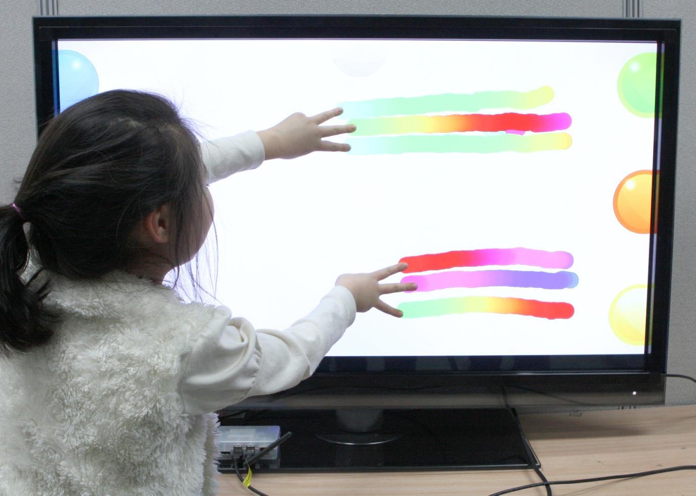
The Android OS, one of the main operating systems for the ODROID, has an intuitive user interface designed for use with a touch screen. This articles describes how to use an ODROID to change any monitor or TV into a giant Android tablet.
Figure 1 - 42-inch Big Giant Tablet with ODROID-XU
Infrared vs Capacitive touch screen
Touch screens primarily use either infrared or capacitive technology. Capacitive touch screens are more popular for smartphones and tablets, but are also more expensive, especially when the screen size is larger than 20 inches. A capacitive screen can only be activated with an exposed finger (no gloves or pointers), and can experience operational difficulties if the monitor is not correctly mounted into a metal housing due to the electrical field. Considering its ease of use and lower cost, the infrared-type touch screen is better suited for this project.
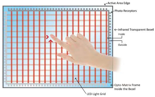
Figure 2 - Principle of IR (Infrared) touch screen
Infrared(IR) Grid touch screens
An infrared touch screen uses an array of X-Y infrared LED and photodetector pairs around the edges of the screen to detect a disruption in the pattern of LED beams. These LED beams cross each other in vertical and horizontal patterns, which helps the sensors pick up the exact location of the touch. A major benefit of the infrared system is that it can detect essentially any input, including a finger, gloved finger, stylus or pen. It is generally used in outdoor applications and point of sale systems which cannot rely on a conductor (such as a bare finger) to activate the touch screen.
Unlike capacitive touch screens, infrared touch screens do not require any patterning on the glass, which increases durability and optical clarity of the overall system. However, infrared touch screens are sensitive to dirt and dust that can interfere with the IR beams, and suffer from parallax in curved surfaces and accidental touch notifications if the user hovers his/her finger over the screen while searching for the item to be selected.
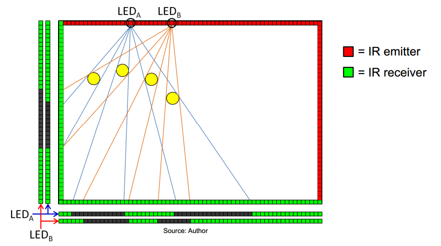
Figure 3 - Principle of IR (Infrared) Multi-touch screen
How to Choose an Infrared touch screen
You can make your own touch screen by following guides found on the Internet, but it is not easy to implement the complex multi-touch algorithm and well aligned IR emitter/receiver pairs, as seen in Figure 4.
Before purchasing an infrared touch screen, it’s important to evaluate its compatibility with Android. It must meet at least one of the following requirements:
1) Is your touch screen listed in the Linux multi-touch compatibility table?
If yes, it will be very easy to activate your touch screen.
2) Is your touch screen Windows 8 compatible?
If yes, you need to add a few lines in the Kernel driver and an input configuration file.
3) Does your touch screen manufacturer supply specific Android driver source code?
If yes, you need to follow their porting instruction.
A touch screen which meets the first requirement was not available in our local Korean or Chinese markets. Some touch screen manufacturers in China offered to supply the driver source code for their products, but the sample code was not useful in the real world. The best alternative was a touch screen that supported Windows 8 HID-compliant Plug & Play.
It’s important to check whether the touch screen is really Windows 8 compatible or not. True Plug & Play devices do not require a separate driver to be installed on a Windows PC. If the touch screen needs a specific device driver, it is not natively compatible with Windows 8 and will be less likely to work with Android.
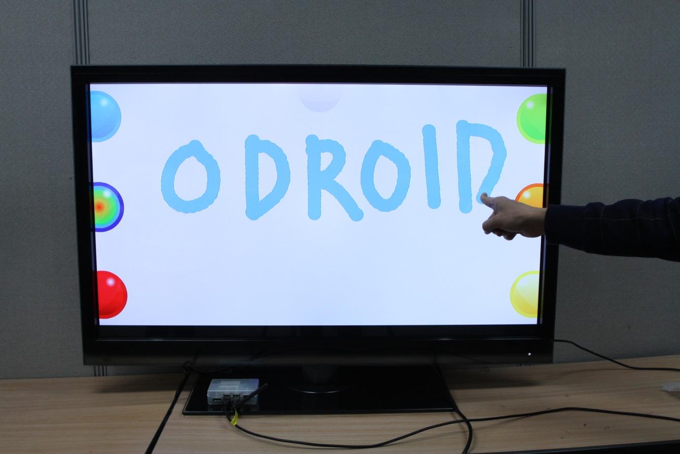
Figure 4 - 42” touch screen connected to an ODROID-XU
Connect the touch screen to Android
There are 4 steps to using the touch screen with the Android OS:
Get the Vendor ID and Product ID from the touch screen USB interface
Modify the files hid-ids.h and hid-multitouch.c, both located in kernel/drivers/hid/
Build the kernel with the HID-MULTITOUCH option enabled, and transfer the kernel image to the ODROID
Create an IDC (Input Device Configuration) file.
Step 1: Check the VID and PID
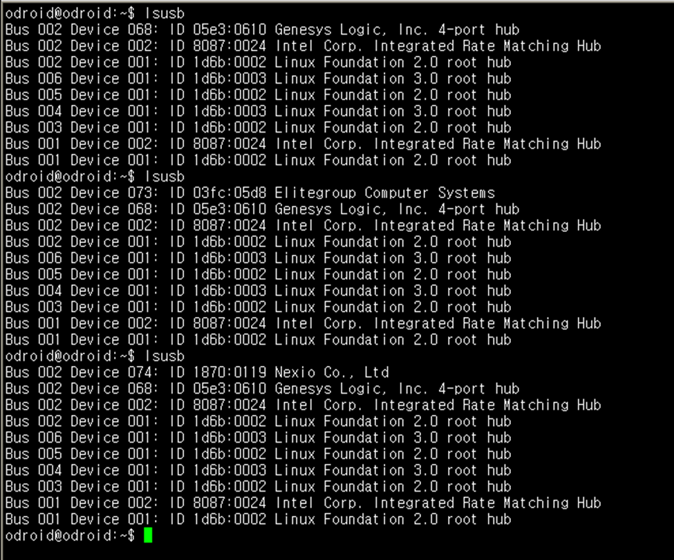
Plug the touch screen into any Linux PC, then find the VID and PID by typing “lsusb” in the terminal as shown in Figure 5.
Figure 5 - Reading the VID and PID of the USB touch screen using a Linux PC
To determine which device entry is associated with the touch screen, list the devices before connecting the touch screen, then list them again after connecting it. The new entry will correspond to the touch screen device.
During our project, when the 23-inch touch screen was connected, an entry of VID:03FC, PID:05D8 appeared in the device list, which represents a touch screen made by Elitegroup Computer Systems. With the 42-inch touch screen connected, an entry of VID:1870, PID:0119 appeared to represent a touch screen from Nexio Co., Ltd. Other touch screens will report different VID, PID and vendor information.
Step 2: Modify hid-ids.h and hid-multitouch.c
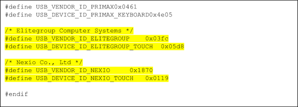
After downloading the appropriate Android kernel source from dn.odroid.com, navigate to the kernels/drivers/hid/ directory, then add the VID and PID to the end of the hid-ids.h header file.
Figure 6 - Example PID and VID values added to kernels/drivers/hid/hid-ids.h.
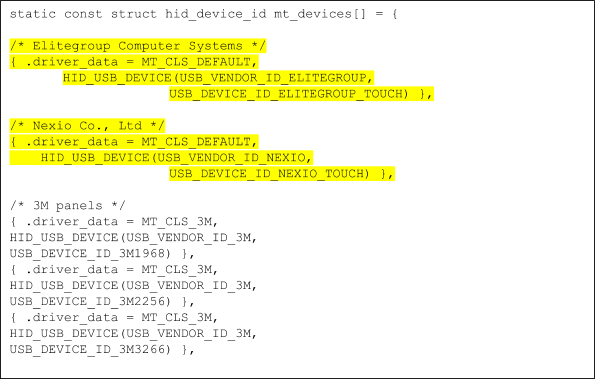
Also, add the new ID in the hid-multitouch.c source file. It must be placed in the hid_device_id mt_devices structure define.
Figure 7 - Example of adding the touch screen ID to kernels/drivers/hid/hid-multitouch.c
Step 3: Build the kernel with the HID-MULTITOUCH option enabled
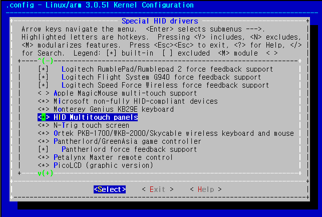
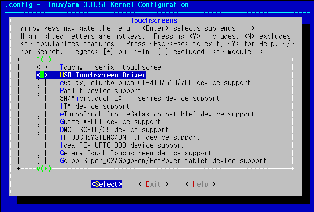
Type “make menuconfig” to configure the kernel, then go to Device Drivers -> HID Devices -> Special HID drivers -> HID Multitouch panels and select it as an embedded driver (*), as seen in Figure 8.
Figure 8 - Configuring the touch screen with an embedded driver in the kernel configuration.
Set below two options as an embedded driver, indicated with an asterisk (*)
Device Drivers -> Input device support -> touch screens -> USB touch screen Driver
Device Drivers -> Input device support -> touch screens -> GeneralTouch touch screen device support
Figure 9 - Configuring the touch screen with an embedded driver in the kernel configuration.
Save the Kernel configuration and compile it to make a zImage.
Transfer the zImage to your ODROID via fastboot protocol in the u-boot.
Step 4: Create an IDC (Input Device Configuration) file
If you don’t make a proper IDC file, the resolution of the touch screen will not match the HDMI resolution.
The file name must be Vendor_xxxx_Product_yyyy.idc (xxxx: Vendor ID, yyyy: Device ID). I made two files for Elitegroup and Nexio. Note that the filename is case sensitive.
Vendor_03fc_Product_05d8.idc and Vendor_1870_Product_0119.idc
Copy the IDC files to your ODROID with the below commands.
How to Attach the 42-inch Touch Panel to the TV Screen.
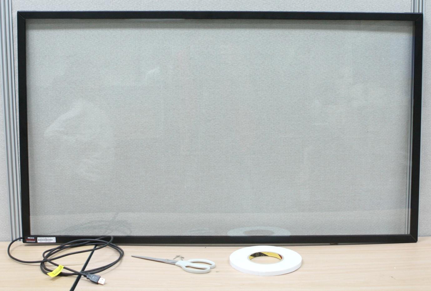
Prepare the touch screen
Figure 10 - Preparing the touch screen
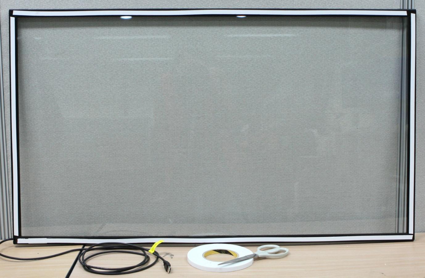
Attach very strong double-sided tape to the frame of the touch screen panel.
Figure 11 - Attaching the double-sided tape to the monitor
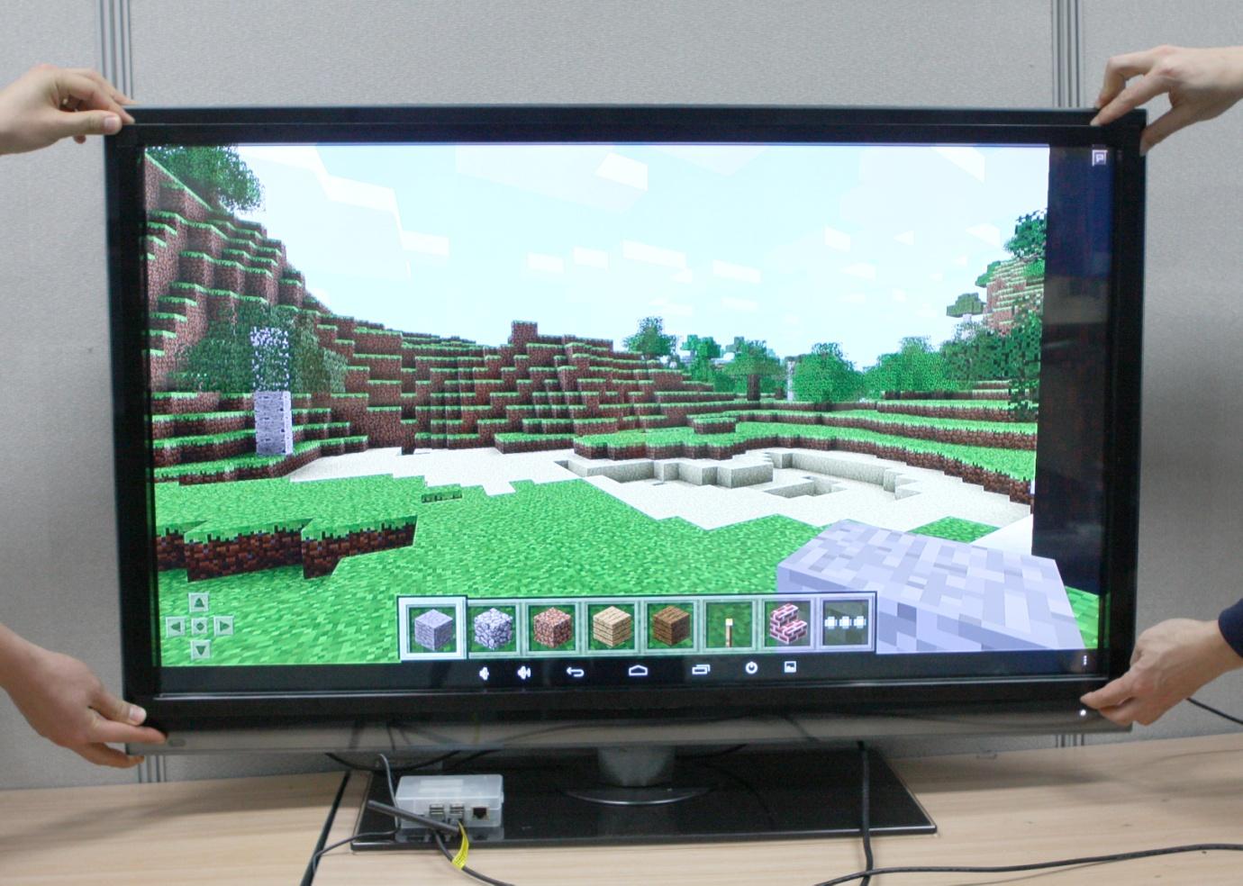
Carefully attach the touch screen to align the viewing window.
Figure 12 - Aligning the touch screen with the monitor
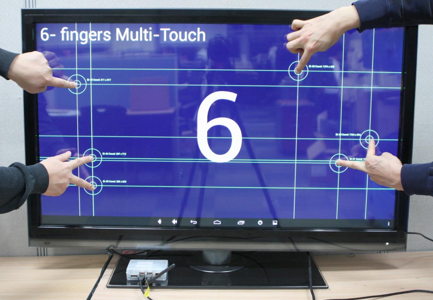
Test the touch screen. Our touch screen could detect up to 6 points.
Figure 13 - Testing the touch screen
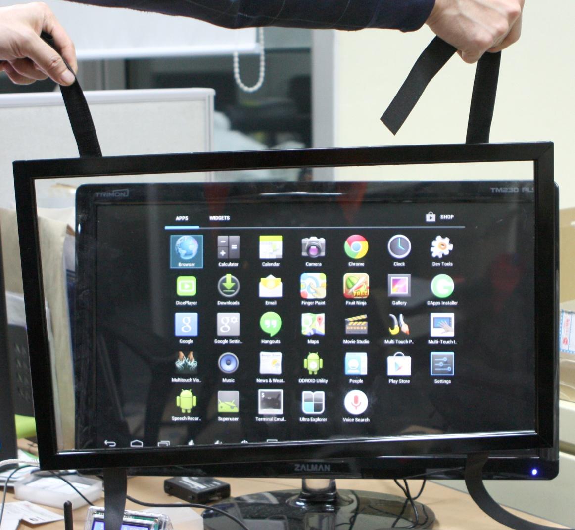
How to Attach the 23-inch Touch Panel to the Monitor Screen.
This smaller 23-inch touch screen panel came with 4 velcro belts and it was relatively easy to assemble.
Figure 14 - 23-inch touch screen panel with velcro belts
Figure 15 - Playing Fruit Ninja on the 23-inch touch screen with my finger.
Conclusion
Besides gaming and personal use, the ODROID is ideal as the core computing device for kiosks, digital signage, human interface research, and more, because of its high performance computing power, relatively low cost, and open platform which allows modifications such as this touch screen.
September 1, 2018By Tobias SchaafGaming, ODROID-C2, ODROID-XU4
In recent articles, I’ve discussed my feelings toward Nintendo and Sega. I consider myself more of a Sega fanboy than Nintendo, although I do enjoy the GameBoy Advance and DS from Nintendo.
Growing up in East Germany during the the 80’s and 90’s, consoles were not that big of a deal for me. In fact, over here in Europe, “micro-computers” were far more common. This also explains why I, personally, prefer modifying rather than turning on a system and working within its limited capabilities. This also means that I am more comfortable playing games on a PC with a mouse and a keyboard than a controller. I know now that, at the time, Amstard CPC, ZX Spectrum, and Atari ST were big players on the market, but for me it was and will always be Commodore, which I grew up with--First with my C64 “Brotkasten” (or “Breadbox”), and later different Amiga models. For this article, I’d like to talk about my experiences during that time, and how I feel about the Commodore today.
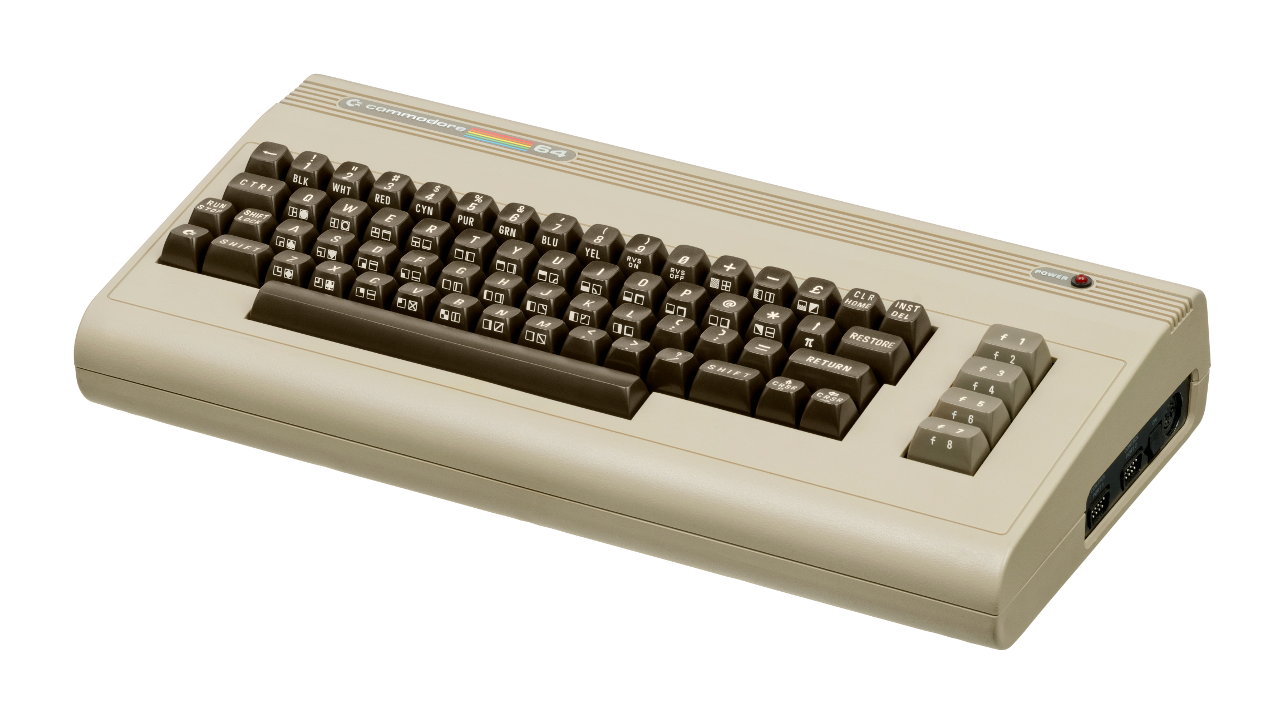
The C64 “Brotkasten”
The C64 was the first micro-computer I had as a child. More accurately, my dad had it and I played on it. Although it was many years ago, I have quite a few good memories with it.
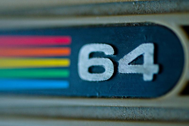
Figure 1 - The Commodore 64 “Brotkasten”
If you’re unfamiliar with Commodore 64, it likely got its name from the 64KB of RAM it had to work with. After loading the BASIC operating system, you would be left with 38911 Bytes of free RAM, which is what would run all your programs and games. It had about 1MHz computing speed and offered 16 awesome colors. Capability-wise, it is probably comparable to the NES.
The Commodore 64 was probably most famous for its impressive sound capabilities for the time. Here is an example of the music for Last Ninja 2: https://www.youtube.com/watch?v=CoGFV_xxR64. There was, and still is, a huge “demo” scene around the C64, with users creating music and graphically impressive videos.
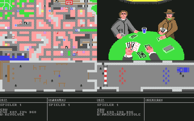
I remember playing a game called Mafia that is probably my fondest memory of the C64. This game had simplistic graphics but the gameplay was lots of fun. It was played using a keyboard rather than joystick, as you were often required to enter numbers and other things.
Figure 2 - Mafia on the C64
Mafia had a lot of things you could do: buy or steal cars--even steal purses from people. You could visit the casino or rent a place to live in. You could try pressure shops into paying you protection money or ask them if they had a job for you (as a hitman). You could work as a bouncer; try to rob a bank; build up your own gang; smuggle booze; buy weapons; train yourself or your gang members; and so on.
You started out as an unknown character working your way up through the ranks of the underground. By doing “bad deeds,” you could get a higher ranked job such as robbing banks or smuggling alcohol. It also allowed you to hire more gang members for even bigger jobs.
The game had a useful bug that allowed you to go to the casino and play for negative money. If you entered a bet of -$1,000,000 and lost, you’d become instantly rich, which made the game so much easier, especially for a child as young as I was then. I enjoyed a text-based game called Hotel due to a similar bug. I built negative numbers of pools in my first hotel and was instantly rich, although that did mean I could never reach 5-Star level, as my hotels had a negative number of pools.
The C64 offered more than just the bad graphics and poorly programming of these two games. No, in fact, many games were quite impressive. Games like R-Type, Maniac Mansion, Turrican, The Last Ninja, IK+ (International Karate Plus), Creatures, Boulder Dash, the infamous Great Giana Sisters, or sports series like Summer Games, Winter Games, and California Games.
I have fond memories of many of these games. My mom, who never played games at all, still played Boulder Dash, which was amazing. Once, playing Maniac Mansion, I did not know the game had a save feature and we tried to finish this game in one day, starting over and over again from the beginning. Turrican was an amazing platformer/shooter with some Metroid-style elements. IK+ is considered one of the best games of all times, and due to Nintendo not wanting to have Super Mario on other platforms, we got The Great Giana Sisters instead. The Great Giana Sisters was a blatant rip-off, but an awesome one, which later became available for the NDS and other platforms.
Figure 3 - R-Type for the C64
Figure 4 - Zak McKracken on the C64. These early adventures were quite difficult
Figure 5 - IK+: one of the best fighting sims out there
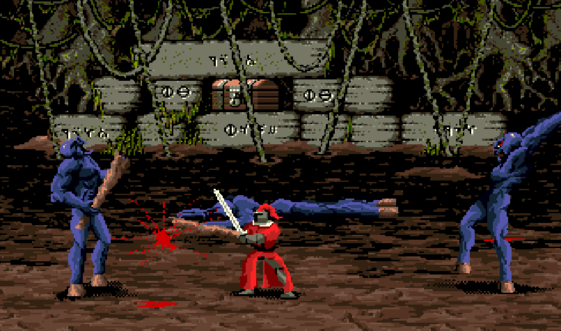
Figure 6 - Last Ninja 2: Awesome graphics, music, and gameplay, but damn hard!
Figure 7 - Collecting diamonds was never as much fun as in Boulder Dash
All in all, the C64 was an impressive home computer. No wonder it was, at one point, the highest-selling home computer of all time. Although I was a small child, I still remember the good times I had playing games on this system. Although newer versions might have better graphics, sometimes the feeling of the original sticks in your memory. That’s definitely the case for me with the C64 and some of its games, such as Boulder Dash. There are other versions of this game with improved graphics, but in my opinion they’re all terrible. The one true version of this game is the one for the old C64 (and maybe some of the clones on other systems).
My Amiga period
While the C64 was an impressive piece of work and flexibility, the Amiga made a mind-blowing jump forward in technology. It was a step forward in the way the jump from NES to the SNES was a step forward.
The story behind Amiga is a long and exciting one. Some would even call it heartbreaking, with its many ups and downs, especially toward the end. If you’re interested in the story behind Amiga I suggest the movie From Bedrooms to Billions–The Amiga Years. It’s a good documentary on how the Amiga came to life and fascinated people. If you never had an Amiga, it might be hard to understand the fascination.
The Amiga was kind of ‘the’ PC of the late 80’s and early 90’s. IBM compatible PCs were expensive. Apple was also very expensive and had not made many changes for quite some time. Atari home computers were still rather limited. Suddenly, a home computer came along that was both affordable and capable. The Amiga was capable of multi-tasking and could choose from 4096 colors--the same as the SNES in mode 7. Later models offered over 16 million colors (24bit), 4-channel stereo audio, standard disks as a storage medium, and much more.
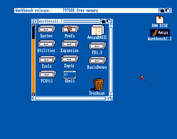
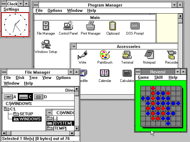
One of the biggest features was its Workbench. Today, most would call it a “Desktop”.
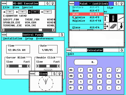
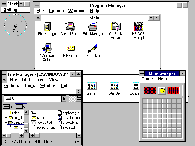
The first commonly used Workbench was version 1.3 which was widely available around 1987 on the early Amigas. Although visually it was not much different from version 1.0 (already released in 1985), it was more commonly used. Around the same time, Windows 2.0, which was still running under DOS, existed on IBM compatible PCs.
Figure 8 - Workbench 1.3 on an Amiga running from HDD
Figure 9 - Windows 2.0 under DOS for IBM PC
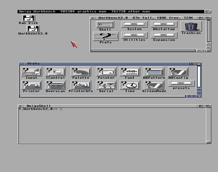
Around 1990 or 1991 Workbench 2.0 was released with a major change in look and feel which made the Amiga look like a decent desktop computer. It required a newer version of the Kickstart (similar to the BIOS of the system) to run, but was still able to run on most older Amigas, as long as they had the newer Kickstart. Kickstart was a ROM that could actually be exchanged on the system’s motherboard.
Figure 10 - A more streamlined Workbench 2.0 for the Amiga
Figure 11 - Windows 3.0 for DOS PCs
A year later in 1992, with newer Amigas and Kickstart 3.0/3.1 available, a new version of the Workbench was introduced. Workbench 3.0 once again showed slightly improved graphics, but the biggest improvement was in its functionality.
Figure 12 - Workbench 3.0 with background pictures for each folder and desktop
Figure 13 - Windows 3.1 for DOS
Workbench was able to run directly from disks or it could be installed on a hard drive, if available. It had interesting features, such as a right-click menu for file operations. Each folder could be configured individually and the changes stored for each folder.
If you’re a PC guru, you have probably heard of something called a “Ram Disk.” It’s a technique that uses part of your RAM as a virtual disk to put data on, improving security or, more likely, speed.
For example, some use a Ram Disk to put their temporary browser files in a temporary folder, first to automatically remove the Ram Disk files when you restart the PC so as not to pollute your hard drive; and second, to speed up loading times of such files, as RAM is much faster than any HDD (and even SSDs).
The Amiga already had this as a build-in function of the Workbench. If you had enough RAM you could copy a game from a floppy directly onto the RAM Disk and start it from there, which meant you never had to load the game from the disk, but rather you could load all data from memory, if you had enough of it.
Although the original Workbench started improving in look and feel in version 2.0, there were still more projects to come.
MagicWB greatly improved the look and feel of any Workbench version 2.0 or higher, allowing your 1992 Amiga to look something like this:
Figure 14 - MagicWB improved the look and feel of the Workbench by adding new icons, backgrounds, and color schemes
The Amiga was an impressive piece of hardware at the time, rivaling modern PC hardware from IBM, Apple, and Atari. The Amiga was used by many different artists, as the mod tracker (also known as the “Protracker” or “Fast Tracker”) was used to create impressive music on the Amiga.
Deluxe Paint for the Amiga was way ahead of its time and used by many artists to create images or manipulate photos (https://www.youtube.com/watch?v=RO7JURHm_jk) long before Adobe Photoshop. In fact, the Amiga had such powerful graphic performance for its time that it was actually used in movie and TV production.
After reading about all the creative stuff you could use an Amiga for, one may wonder.. What is he talking about? I thought we were talking about about games?
Well, in spite all the creative tasks you could do with the Amiga, it was still mainly used for games. There are nearly 1800 games for the Amiga, putting it on par with worldwide releases for the SNES (only 720 of the SNES releases were released in the USA).
With this impressive library the Amiga had games for everyone: RPG, adventures, racing, fighting. Every genre of game existed for the Amiga. Most of my childhood memories up until the time I was about 14 centered around the Amiga and its games. There were so many impressive titles for the system, I wouldn’t even know where to begin.
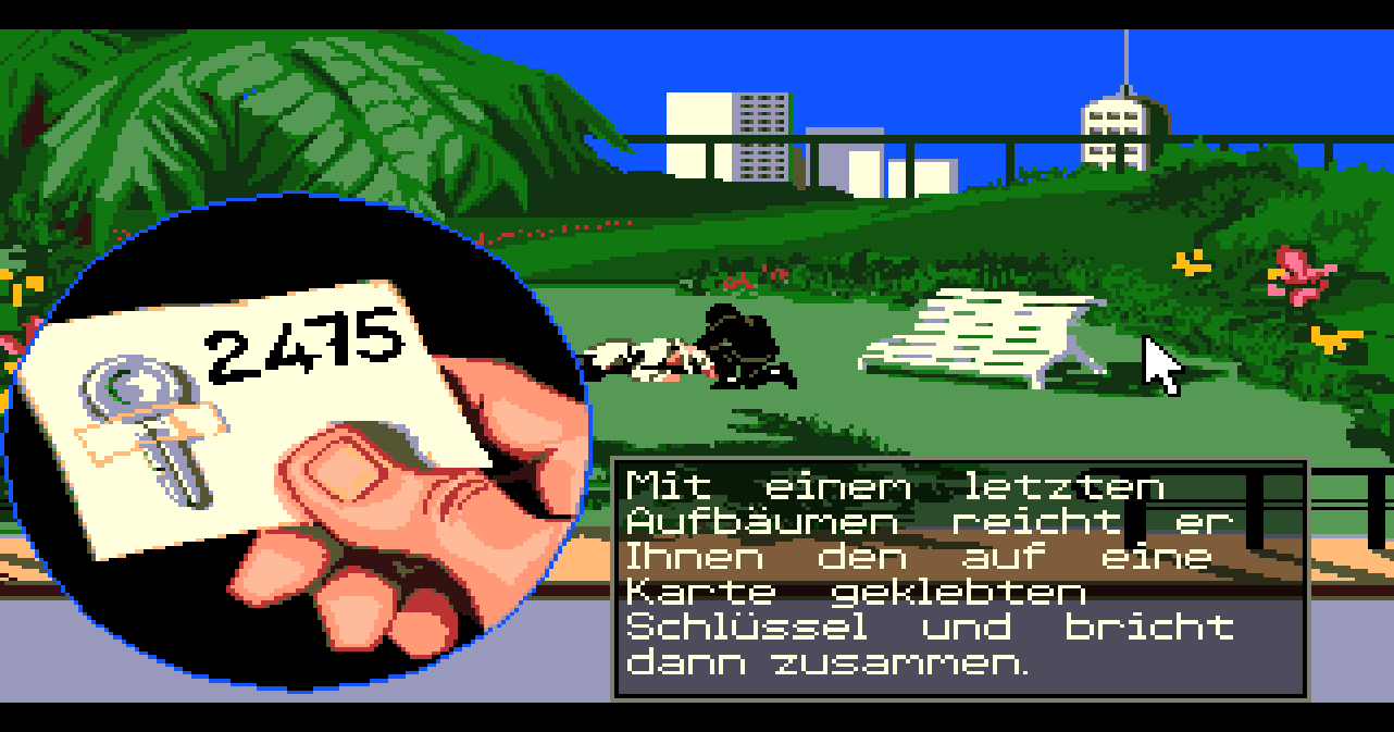
I played tons of adventure games on the Amiga, such as Monkey Island 1 and 2, Indiana Jones 3 and 4, Beneath a Steel Sky (which came on fifteen disks), Simon the Sorcerer, Operation Stealth, Dune, Loom, and many more.
Figure 15 - The Monkey Island Series is an extremely funny adventure series. If you never played them, you really missed out on gaming history
Figure 16 - Operation Stealth was a detailed, complex secret agent adventure on the Amiga
Many games on the Amiga were superior to their PC counterparts. Especially in the early years, the Amiga trumped other systems with better graphics and better music. Many games I later replayed on the PC felt strange for that reason as I was known to “better” on the Amiga than when I replayed them on the PC. The Amiga also had a lot of ports from older C64 games with improved graphics.
It’s really hard for me to pick favorite games for the Amiga, as I liked many games of that time and era.
Rodland, a fun little platformer. Lost Patrol--in this game you have to lead a group of American soldiers stranded in Vietnam back to an Army base. This game is very hard, but beautifully rendered and quite complex. The music alone deserves an award; it’s one of the best soundtracks I’ve ever heard in a video game. Persian Gulf Inferno, a platformer/shooter where you had to free an oil platform from middle eastern terrorists. Rainbow Island, which is said to be the best port of all on the Amiga. Arabian Nights, a platformer where, although not related to the Disney movie, you would play as an Aladdin-type character, also had very good music and graphics for it’s time.
Figure 17 - First Samurai on the Amiga. I loved swinging that sword!
First Samurai was a platformer with fighting elements, great graphics, sounds, and even clear voice samples. Fire and Ice was an even more awesome platformer, and The Chaos Engine (aka Soldiers of Fortune) was an amazing cooperative run and gun. Flashback was an interesting platformer/action adventure, which not many people liked all that much, but I enjoyed it on the Amiga.
Figure 18 - Flashback was ported to nearly all systems at the time, but the Amiga version is the one I played and finished
I played over a hundred games for the Amiga, as it had some amazing titles. Until I got my first PC I played my Amiga hardcore, moving through different models over time (my dad owned them, I just played on them.)
I started with the most common model, the Amiga 500, which we got a hard drive for later on. We also got a Kick-Switch, which allowed us to switch between Kickstart 1.3 and 2.04, and RAM expansion.
One of my uncles had an Amiga 600 but it was unimpressive. He had a tiny, original Amiga HDD built into the system, and even with compression his HDD was constantly full.
Figure 19 - Moonstone was a fun, but very bloody game
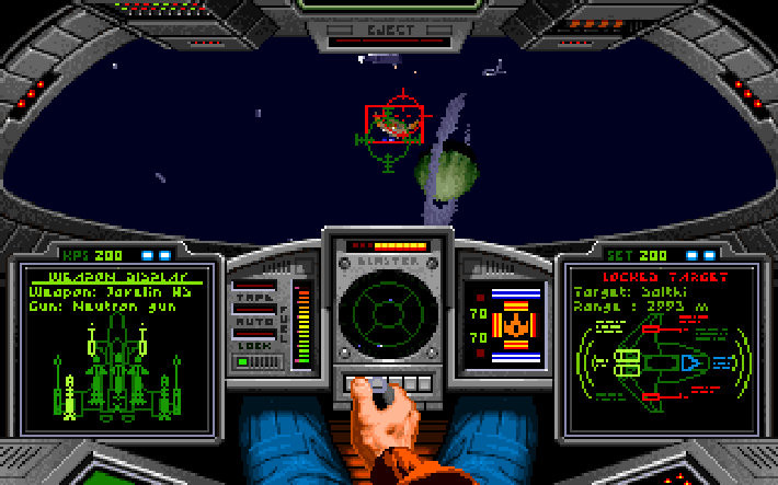
Figure 20 - Wing Commander for the Amiga started my passion for space simulations
Later on, we got an Amiga 1200. This was a new and improved system, using Kickstart 3.1 and an AGA chip, which was an improved graphics chip that allowed for 16.7 million colors instead of the 4,096 colors of the Amiga 500. We also briefly had an Amiga CD32, the first 32-bit CD-based gaming console, but although the CD format was promising, most games were just straight ports of Amiga 1200 titles.
The Amiga was fascinating. Although I played many games on it, I still barely scratched the surface of the library of games available.
Final Thoughts
So, I return to the same question I’ve asked throughout this series in regards to other systems: Am I a Commodore fanboy?
If you grew up in Europe during the late 80’s and 90’s and did not know what a C64 or an Amiga was, you were likely living under a rock. I will always speak proudly of my Amiga and the games I had. Both C64 and Amiga games can be emulated for the ODROID, and you can relive your memories that way.
But lately I realized that if I wanted to suggest games to someone that never had a C64 or an Amiga, and did not grew up with these systems, it’s hard to make them feel the same as I felt back when I was a child. Many of the games existing on the C64 and Amiga were ported to other systems, and although the Amiga is probably still the best platform for some of these games, not everyone likes the type of strategy games, simulators, or adventure games that made these systems great.
In fact, if I wanted to relive my adventure games I most likely go to ScummVM directly, where I can play these games without emulation. If I want to play Dune 2, the XCOM Series, I’d rather choose Dune Legacy or OpenXCom--improved Linux versions of these games for ODROID. If you look into the game library you will find very little IPs that survived the passage of time. You won’t find any well known titles like Super Mario Bros., The Legend of Zelda, or Sonic the Hedgehog on Commodore systems.
There are still some games I’d say “Hey! Go play that on the Amiga!” These are great games and do not exist on any other system, but the list is very short. The Amiga and C64 are great systems with a lot of retro charm, but I notice myself more drawn to SegaCD, Sega Saturn, or even Master System games than I am to games for the Amiga or C64. I plan on going back to the Amiga to replay some games, or even try out new games, but as much as it’s a great memory of my past, I can’t say I’m that into Commodore anymore. Therefore, as hard as this is to admit, I must say that, no, I’m no longer a Commodore fanboy.
Coding Camp - Part 3: Control an LED
September 1, 2018By Justin LeeODROID-GO, Tinkering, Tutorial
Let's make the LED blink continuously. First, open a new sketch by pressing the shortcut CTRL-N. Controlling the LED very easy, the pin number for the LED is 2, so let’s define that with a Preprocessor. Next, we have to set the pin to output mode. Use the pinMode() function to do that.
#define PIN_BLUE_LED 2

void setup() {
// put your setup code here, to run once:

pinMode(PIN_BLUE_LED, OUTPUT);
}

void loop() {
// put your main code here, to run repeatedly:
}
Now the pin is ready to use. You can set the pin signal level by using the digitalWrite() function. This function has to be in loop() to run repeatedly. The delay() function is used to slow down the rate of blinking.
#define PIN_BLUE_LED 2

void setup() {
// put your setup code here, to run once:

pinMode(PIN_BLUE_LED, OUTPUT);
}

void loop() {
// put your main code here, to run repeatedly:

digitalWrite(PIN_BLUE_LED, HIGH);
delay(500);
digitalWrite(PIN_BLUE_LED, LOW);
delay(500);
}
Press CTRL-U to compile and upload the sketch. Then, you can see the blue LED blinking.
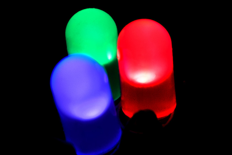
Give the LED a breathing effect
Figure 02 - the LED ‘breathing’
By adjusting the analog output value, we can make the LED show a breathing effect. This technique is known as PWM. Arduino gives us wrappers that help control the GPIO pins as well as the PWM features. Generally, these PWM functions are analogRead() and analogWrite(), but they are not yet available in ESP32 so we must use the ledcRead() and ledcWrite() functions to control the LEDs.
The way to control the PWM values in a ESP32 is different from other Arduino boards. These functions use the LED PWM hardware feature of ESP32 which is located in ledc.h, LED Control function header. In ESP32, the LED PWM is composed of 16 independent channels, and we can configure them with a duty cycles with a resolution and wave period.
First, we should choose a channel to attach the LED to. Channels 0 to 7 are available, we will use channel 1 in this example. Define the channel and the blue LED through a Preprocessor macro.
#define PIN_BLUE_LED 2
#define PWM_CHANNEL 1

void setup() {
// put your setup code here, to run once:
}

void loop() {
// put your main code here, to run repeatedly:
}
Set the pin mode of the LED to output:
#define PIN_BLUE_LED 2
#define PWM_CHANNEL 1

void setup() {
// put your setup code here, to run once:
pinMode(PIN_BLUE_LED, OUTPUT);
}

void loop() {
// put your main code here, to run repeatedly:
}
Attach the LED pin to the channel we defined. Next, set up the channel to operate at 12kHz with 8 bit resolution.
#define PIN_BLUE_LED 2
#define PWM_CHANNEL 1

void setup() {
// put your setup code here, to run once:
pinMode(PIN_BLUE_LED, OUTPUT);
ledcSetup(PWM_CHANNEL, 12000, 8);
}

void loop() {
// put your main code here, to run repeatedly:
}
Lastly, add the breathing code into the loop() function. We defined a variable called pinVal as a global variable to prevent allocating new memory repeatedly in the loop() function. The type of pinVal is an unsigned char since the PWM value ranges only 0-255.
#define PIN_BLUE_LED 2
#define PWM_CHANNEL 1

unsigned char pinVal = 0;

void setup() {
// put your setup code here, to run once:

pinMode(PIN_BLUE_LED, OUTPUT);
digitalWrite(PIN_BLUE_LED, HIGH);

ledcAttachPin(PIN_BLUE_LED, PWM_CHANNEL);
ledcSetup(PWM_CHANNEL, 12000, 8);
}

void loop() {
// put your main code here, to run repeatedly:

for (; pinVal > 0; pinVal--) {
ledcWrite(PWM_CHANNEL, pinVal);
delay(3);
}
for (; pinVal < 255; pinVal++) {
ledcWrite(PWM_CHANNEL, pinVal);
delay(3);
}
}
Press CTRL-U to compile and upload the sketch, then you can see the blue LED breathing.
A completed example
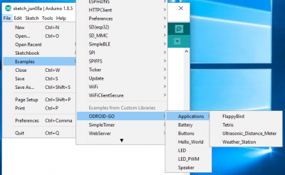
The complete example is available can be loaded in the Arduino IDE by clicking the Files → Examples → ODROID-GO → LED or LED_PWM menu to import and press CTRL-U to compile and upload.
Figure 03 - loaded completed example in arduino IDE
Additional information
For extra information and help, please use the following links, or ask on the ODROID forums:
Refer to the Arduino official documents. This provides useful common functions with great instructions.
Refer to the ESP32 official programming guide. Most of the ESP32 specific functions are introduced here.
Coding Camp - Part 4: Read the 12 buttons status on the ODROID-GO
September 1, 2018By Justin LeeODROID-GO, Tinkering, Tutorial
For this article, we will learn how to read the status of the buttons with Arduino. A simple output will be shown on the LCD. Before getting started, make sure you've followed these guides:
Refer to the Arduino official documents. These provide useful common functions and great, detailed instructions. You can also refer to the ESP32 official programming guide. Most ESP32-specific functions are introduced here.
Get the status of the buttons
The ODROID-GO has 10 buttons available:
4 for direction pad
2 for an action
4 functional buttons
Thanks to the GO library, we can get the status of each buttons easily. Firstl, initialize the LCD with the “GO.begin()” function. Set text size to 2 since the default text size will too small to read.
#include

$ void setup() {
// put your setup code here, to run once:
GO.begin();
GO.lcd.setTextSize(2);
}

$ void loop() {
// put your main code here, to run repeatedly:
}
Add an independent function to display the status, and name it “displayButtons()”. This function has two steps:
“GO.lcd.clear()” to clear any LCD content previously shown.
“GO.lcd.setCursor()” to set the start point to print a string. The two parameters (0, 0) means top, left.
#include

$ void setup() {
// put your setup code here, to run once:
GO.begin();
GO.lcd.setTextSize(2);
}

$ void displayButtons() {
GO.lcd.clear();
GO.lcd.setCursor(0, 0);
}

$ void loop() {
// put your main code here, to run repeatedly:
}
Fill “displayButtons()” out with the code below. This will display whether any buttons are pressed or not. When a button is pressed, then a “Pressed” string will appear beside the element that corresponds to the button.
All of the available buttons for the ODROID-GO are available as instances of the Button class.
The Button class has some helpful functions to let us know the button's status. Thus, we use “isAxisPressed()” and “isPressed()” functions to know if a button is currently pressed or not.
If the button is pressed, that functions returns not 0.
The “isAxisPressed()” function is only for the direction pad. If the button is pressed, it returns 1 or 2 to distinguish the direction.
“isPressed()” function is for the other buttons. If the button is pressed, it returns 1.
Lastly, we have to fill the “loop()” function out to show the status on the LCD. There are three functions to add:
“GO.update()” to update the buttons' states so that the “isPressed()” functions works well.
“displayButtons()” to add result strings to the LCD.
“delay(1000)” to prevent the LCD from blinking too fast when “GO.lcd.clean()” function acts.
Press CTRL-U to compile and upload the sketch. Then, press any button to show the “Pressed” string besides that button. As you may have noticed, you will need to keep pressing it until the LCD is updated due to the “delay(1000)” function.
A completed example
The complete example is available by clicking the Files → Examples → ODROID-GO → Buttons menu to import and press CTRL-U to compile/upload.
Figure 1 - A completed example
High Performance Computing in the Home: Getting started with ODROID and MPI
September 1, 2018By Cooper Filby and Anthony SkjellumLinux, Tinkering, Tutorial
In this article, Cooper Filby and Anthony Skjellum of Runtime Computing Solutions LLC http://www.runtimecomputing.com, outline the setup and configuration of a basic “headless” cluster with the end goal of running parallel programs based on message passing, using the Message Passing Interface (MPI) parallel programming model in particular. There are a number of prebuilt Linux operating systems available for ODROID boards from the Hardkernel website. To get started, download the Ubuntu Server image for your ODROID model and extract the .IMG.XZ archived image using an archiving tool such as 7zip on windows, or by typing “xz” from the Linux command line. Finally, you can copy to the medium of your choice, such as an SD card or an eMMC module, using the “dd” command on Linux/OS X systems or the Win32DiskImager.exe for ODROID on Windows. For more detailed instructions on copying over the OS, please refer to Bohdan Lechnowsky’s article titled “Installing an OS on an ODROID” from the January 2014 issue of ODROID Magazine. We recommend using the eMMC modules available from Hardkernel for better performance, but SD cards work well too.
Connecting to your ODROID
Since we opted to use the Ubuntu Server image for our ODROIDs, we can connect to our XU-E systems (we’ll call them nodes for simplicity from now on) via the ssh protocol using Terminal (or Putty if running Windows) in order to continue setting up our cluster. Because of potential initial hostname and MAC address conflicts that we will resolve in the next section, we will need to boot the first ODROID and set a few settings before starting the second.
[Editor’s Note: If one is available, a development machine running Linux or Windows is recommended to more easily setup and reboot the cluster, troubleshoot hardware problems, and other necessary debugging. An alternative to using a separate computer is to plug a USB keyboard and HDMI cable into the first ODROID and use it directly to bootstrap the cluster instead of via SSH as described in the next few paragraphs. Press Ctrl-Alt-F1 to use the framebuffer console if X11 is not running.]
In order to connect to your ODROID, you'll need to discover the hostname or IP address of the board. For the Ubuntu server image we used on our XU+E cluster, the default hostname is “odroid-server”, while for other images we've used, it's been “odroid”. Most home networks should support DNS by default, which will allow you to connect simply by the
hostname. If this fails, you can alternatively connect using the IP address assigned to the ODROID by your router instead. If neither of the hostnames resolves for you, check your router's lease table to search for the IP address, often labeled as the DHCP client table in the router’s admin panel.
Since we used identical copies of the same image on both nodes, by default they had a hostname conflict, which we resolved by bringing them online one at a time, then changing the individual network settings. If you don’t have access to the router’s admin panel, you can also make use of the nmap command to scan your network for hosts to find the ODROIDs, if you know your network information. For example: “nmap 192.168.1.0/24”. Look for a host that has port 22 open.
Power on one of the ODROIDs, then enter “ssh odroid@ubuntu-
server” (or “ssh odroid@xxx.xx.xx.xxx”, if using the IP address) in the Terminal or Putty window of the host computer, which will establish a secure connection to the ODROID. To login, type “odroid” as the password.
Once the command prompt appears, you may want to run "sudo apt-get update && sudo apt-get upgrade" to ensure that your OS is up to date. Furthermore, we recommend you run the "passwd" command and change the password for the odroid user to something a little more secure, or creating new user accounts with the "adduser" command, such as by running "sudo adduser kilroy". (Generally speaking, do three things key with your node passwords: make them long, make them hard to guess, and store it in a secure location.)
Configuring Networking
Before getting both ODROIDs online, we need to change a few settings as to eliminate hostname and MAC address conflicts that may occur on your home network with an ODROID cluster. To change the hostname, we will need to edit two files, /etc/hostname and /etc/hosts, changing "odroid-server’ to the hostname of your choice and rebooting the machine so the changes take effect. For the purposes of this article we will use odroid-server0 and odroid-
server1 to refer to the first and second ODROID respectively. Alternatively, if your operating system supports it, you can also type "sudo odroid-config" to change the hostname. You can use other names of your choice; they have to be unique to each node.
The MAC address conflict was a subtle issue that we encountered when we first set up multiple ODROID XU+E’s. We found that, by default, the onboard ethernet devices all shared the same MAC address, which made it impossible to work on a single ODROID if multiple were powered online and on the same network. If the two ODROIDs you’re working have identical MAC addresses, there are two straightforward ways to resolve this: 1) configure one (or both) of the ODROIDs to use a different MACaddress, or 2) setup USB ethernet dongles, which should all have unique MAC addresses. The specific values you choose really don’t matter, as long as you keep them unique on your Local Area Network (LAN).
To change the MAC address of the onboard device, edit /etc/network/interfaces with your text editor of choice, and add the line "hwaddress ether newmac", where newmac is an address in the format “b6:8d:67:7b:cb:e0” underneath the following labels:
auto eth0
iface eth0 inet dhcp
Then, reboot the ODROID so the changes take effect. Make sure to verify the new address using the ifconfig command. Alternatively, you can opt to plug your USB Ethernet adapters into the USB 3.0 slot, and then run "ifconfig -a | grep eth", which should yield a list similar to this:
eth0 Link encap:Ethernet HWaddr b6:8d:67:7b:cb:e0
eth2 Link encap:Ethernet HWaddr 00:13:3b:99:92:b1
By default, eth0 will be the onboard 10/100 ethernet connection, while the second ethernet device (in this case, eth2) will be the USB Ethernet Adapter. If only eth0 shows up, try reseating your USB Ethernet adapter and/or verifying that it works on another machine. To set up the adapter for using DHCP on boot to get an IP address, we will need to modify /etc/network/ interfaces and add the following two lines between the entries for auto lo and auto eth0:
auto eth2
iface eth2 inet dhcp
Use the appropriate ethernet device id previously found with ifconfig (in this case, eth2). Then, power down the ODROID, put the ethernet cable that was attached to the the onboard device into the USB ethernet adapter, and power the ODROID back on. If, for some reason, you aren’t able to connect, try plugging the cable back into the onboard slot and verifying that the USB ethernet adapter is still showing up using the “ifconfig -a” command. It’s also possible that the ethernet device ID itself has changed if the adapter is unseated, in which case you can update the /etc/network/interfaces file accordingly.
At this point, the ODROID should be configured and accessible on the network. Before heading on to the MPI section, configure the second ODROID using the same steps described above.
Message Passing Interface (MPI)
Now that we have two nodes configured appropriately, we can now start looking towards how we can execute HPC jobs on our two-node cluster. A parallel programming environment such as MPI helps you do this. MPI takes care of starting up the processes that make up the parallel programming model, and provides a standardized application programming interface (API) for those cooperating, communicating sequential processes to use to make the parallel program work. To accomplish this, we will make use of MPI, or Message Passing Interface, which provides an API that allows nodes to send and receive messages while processing jobs. A command called either mpirun or mpiexec will start all the processes needed across your ODROIDS under your control. There are two common open source MPI implementations available for download - MPICH and OpenMPI. For ODROID clustering purposes over Ethernet, both work equally well. Both of these MPI implementations are available through ap.
To install MPICH, run "sudo apt-get install mpich2", or run "sudo apt-get install openmpi-bin" to install OpenMPI as an alternative.
What you can do once you’ve loaded MPI:
1) Run example programs that use multiple cores on a single ODROID
2) Run example programs that use both ODROIDS and a total of 8 cores.
3) Learn how to build your own MPI programs.
In this article, we’ve focused on showing you how to do the first and the second approaches. You can read the example programs that come with OpenMPI and MPICH to learn more. There are also a number of excellent online tutorials and a few good books on programming MPI, such as “Using MPI” from MIT Press (one of us co-authored that book).
Building it Better
The content of this article represents just a fraction of what we will be able to do with our cluster down the line. While this setup is more than adequate for handling two nodes and only a few users, if we want to grow our cluster, we will want to make use of a dedicated head node to better handle a larger number of users and nodes. In addition to allowing us to hide cluster traffic from the rest of the network, this head node will also host services that will streamline cluster management, such as LDAP for user management, Puppet for content management, NFS for file sharing, and various networking services.
In part two of this series, we will begin to convert odroid-server0 into a proper head node.
Home Assistant: Tracking People With Wi-Fi Using Kismet
September 1, 2018By Adrian PopaLinux, Tinkering, Tutorial
It seems that tracking people has grown into a multi billion dollar market (https://goo.gl/T1XZS8) and can be used either to build profiles on people (learn a person's habits and monetize based on them), or to optimize stores and venues based on where the people go to. For example, if a clothes store can track your movements (and remember where you have been on previous visits) they can build a profile with the kinds of clothes you like to look at and can bombard you with personalized advertisement later on. People tracking can be done in lots of ways, from face recognition to wifi/bluetooth tracking, with varying amounts of accuracy. As with any technology, tracking can be used to do good (e.g. find buried people after an earthquake) or evil (stalk your cute neighbor next door).
In my case I want to track when the nanny is home or not so that I know I have to go to pick up my son from the park instead. This can be done remarkably easy with wifi tracking and Home Assistant. The problem is my nanny's phone does not connect to my wifi network, so I need to use a passive way of monitoring.
We have discussed in the past how wifi operates (https://goo.gl/yWD2j1) and also how it can be sniffed (https://goo.gl/uEsdMo). In short - clients and access points regularly broadcast their SSID or send probe requests to ask for any/specific SSIDs in the area. All wireless traffic (even encrypted traffic) has layer 2 information (MAC addresses) unencrypted and this can be sniffed. In order to sniff wifi traffic you have to have a wireless card that supports monitor mode (HardKernel wifi adapters support it). Typically MAC addresses are unique per device and can be used to track a specific device, so anyone with a monitor wifi card can track you (as we are about to see).
Installing bleeding-edge Kismet
The simplest way to start listening to the wifi spectrum is to install kismet. Kismet takes care of putting your wifi adapter in monitor mode and can also log all the sniffed traffic. In order to have access to the new UI and also to have a REST API you will need to install kismet from sources instead from a package manager (both Ubuntu 16.04 and 18.04 have too old versions of kismet). You can get general instructions from here: https://goo.gl/qjwLKb.
You will need to install some development tools first:
Compiling kismet will require more RAM than you probably have, so it is a good idea to enable disk-based swap. I managed to get away with 1G swap for my C2, but if you have more space available, you can create a bigger swap file:
The systemd startup script starts kismet as a daemon, with no logging, bound to wlan0 (which will be put in monitor mode). I have had some problems with the USB ports on my C2 (mainly because I am running several gadgets off an unpowered hub) and sometimes the wifi adapter would lock up requiring a reboot. If I restart kismet every hour the problem goes away - this is what WatchdogSec does.
Once started, you can connect to its web interface on http://:2501/. You have read-only access without being authenticated, but you will need to create a user if you want to change settings. When you start kismet for the first time a random password for the user kismet will be generated and stored in /root/.kismet/kismet_httpd.conf.
Figure 1 - Kismet UI
Finding out the MAC
In order to track somebody via wifi, you will need to get their MAC address one way or another. You can ask for it, or use social engineering to find it out (e.g. ask to see their network settings in order to troubleshoot some made-up issue), or you will have to work for it in case you do not have access at all to the terminal you want to track.
If you are stuck in the latter case you will have to make some assumptions:
The tracked person has wifi open and makes probe requests
The tracked person has a static MAC
You know when the tracked person is within sniffing range
In this case, here is the plan. Start kismet in monitor mode and have it log to file (sqlite3 database) ambient traffic. Stop the capture before the person of interest is within range and restart a new capture when the person is around. Leave the capture going for as long as possible (at least 10-15 minutes) and stop it when the person is no longer around.
Next, extract the MAC addresses from both data sets and do an difference. You are interested in MACs that exist when the target was around but do not exist in the first dataset (remove MACs found in the first data set from the second one). You should be left with a smaller list of MACs - one of which is the target's MAC. You can further refine this based on timestamps - eliminate MACs seen after the target was no longer around or before the target arrived. If you still get a list of a few MACs and you cannot exclude some based on manufacturer (e.g. they are all Samsung phones), you will need to repeat the process a different time and see which MACs from a new recording are the same as the potential target MACs. By process of elimination, you should end up with only one MAC that appears in all captures and is not "a regular". If you are doing this in a "quiet" area (e.g. a house) you will find out the MAC pretty quickly. If instead you are doing this in a crowded area, you will have to do more iterations.
Let us see the plan in action.
First you need to do the capture. To enable this, edit /usr/local/etc/kismet_logging.conf and change log_prefix=/tmp/.
Next, edit the systemd service and remove the "-n" command-line switch, so that logging is done:
$ sudo sed -i 's/--daemonize -n/--daemonize/'
/etc/systemd/system/kismet.service
$ sudo systemctl daemon-reload
$ sudo service kismet restart
Now you will get hourly log files in /tmp with the devices that kismet has seen. Once you have enough data, you can turn off logging and restart kismet by editing the systemd service and adding "-n".
Next you will need to divide the files you collected into two groups. The directory "0" will hold files where the target is known not to have been present, while the directory "1" will hold files where the target might have been present. You can do this division based on time (you have one hour slots by default).
Next comes the hard work. We need to extract all MACs from all files in both folders and compile two lists - MACs from folder 0 and from folder 1. We can get data from inside the kismet log by using sqlite3 with an SQL syntax. Since sqlite3 doesn't support wildcards for file names, we need to do some bash trickery and iterate over each file.
$ sudo apt-get install sqlite3 bc
$ for file in 0/*.kismet; do sqlite3 -csv "$file" 'select
devmac,first_time,last_time from devices;' | tee -a 0/0.dump; done
$ for file in 1/*.kismet; do sqlite3 -csv "$file" 'select
devmac,first_time,last_time from devices;' | tee -a 1/1.dump; done
For both directories we have dumped out the MAC, start time and end time from Kismet. Next step is to aggregate the data (since having multiple files leads to duplicate entries). We will use sort + uniq and keep only the MAC address. In my case I ended up with 701 MACs which were known not to be the target, and 229 MACs that might have been the target.
At this step, we need to reduce this potential list further and we will eliminate MACs that have been seen only briefly (for less than 100 seconds) because they are likely just people or cars passing by. This further reduces the potential MAC set to 152 in my case.
Now the process of elimination begins - we delete the matching lines between the two files. For this we can use grep -v to print non-matching lines and we search for the contents of 0/0.mac inside 1/1.mac:
$ grep -v -f 0/0.mac 1/1.mac > potential.mac
This leaves me with only 27 MACs to further investigate. I could filter by device vendor (if I knew it). One way to keep only Samsung devices is to look-up their MAC in the OUI database. You can install a local copy of the database with the ieee-data package and you can look up all the MACs and keep only the ones registered to Samsung.
$ sudo apt-get install ieee-data
$ while read line; do match=`echo $line | cut -c 1-8 | sed 's/://g' | xargs -n 1 -I{} grep {} /usr/share/ieee-data/oui.txt | grep -i Samsung`; if [ -n "$match" ]; then echo "$line"| tee -a samsung.mac; fi; done <potential.mac
I get only 4 MACs after applying this filter, so I'm getting closer. In order to further refine this I need to do more sniffing when the target is around and find which MACs from the new recording are found in the old recording until I am left with only one. Or, I could monitor all 4 and see inside Home Assistant which one behaves correctly.
Adding a custom device_tracker in Home Assistant
The advantage of the new kismet you just installed is you can query it via its REST API and get a JSON response of new devices that match your search criteria. The REST API documentation is available here: https://goo.gl/JFpnZM.
The plan is to implement a custom device_tracker as a module in Home Assistant that will take a list of MAC addresses or a list of SSIDs and will ask a kismet instance if it seen those MACs/SSIDs in the last 30 seconds. If Kismet has seen them, it will report their names, which in turn gets relayed to Home Assistant.
Currently, the kismet device_tracker can be used as a custom component. Hopefully, in the future when the REST API stabilizes it can be merged directly into Home Assistant. You can install it following these steps:
$ sudo su - homeassistant
$ cd .homeassistant
$ mkdir -p custom_components/device_tracker
$ cd custom_components/device_tracker
$ wget -O kismet.py https://goo.gl/WPGZZA
You will need to edit configuration.yaml and add the component:
Once you restart Home Assistant, the component will connect periodically to the kismet instance and query for the devices you listed. It will get results for the last "interval_seconds" period (e.g. for the last 30 seconds), so even if the mobile device was active for a little while in that interval it will get picked up and reported. The length of interval_seconds only affects how quickly a device is seen, not whether it is seen or not.
The parameters have the following meaning:
interval_seconds - how often to ask for updates from the kismet server
host - the kismet server IP/FQDN (127.0.0.1 by default)
port - the port where kismet is running (2501 by default)
consider_home - how long should a client be still considered at home if he has not been seen (7 minutes is ok for clients with wifi open, but not associated to a network. May depend from device to device)
clients - a list of MAC addresses to look for. Can be a regular expression
ssids - a list of SSIDs to look for. Can be a regular expression
Devices which are discovered are added to known_devices.yaml and can be accessed as an entity inside Home Assistant. Once the devices have been discovered you can customize their entity name and add an image as well by editing known_devices.yaml
Figure 2 - known_devices.yaml entry
You can further add the entities to be tracked inside a group and display them in the main Home Assistant UI.
If you are using Custom UI (https://github.com/andrey-git/home-assistant-custom-ui/) with Home Assistant you can also display the last changed time (e.g. "2 minutes ago") below the entity name so you can get a quick indication how long ago a person has arrived or left without expanding the card. To do so, make sure you are on the latest CustomUI version (run ./update-custom-ui.sh from within ~homeassistant/.homeassistant) and add the following in the configuration:
So, how well is this working? It depends on the device being tracked. Older/cheaper devices make no attempt to hide their MAC and are easily picked up (like my Samsung J3). Newer/more expensive devices use random MACs to do probe requests and are harder to pin down. It is not impossible though. All phones use their real MAC address when connecting to a known access point. So, if you (separately) broadcast a list of popular access point names from the target's area (e.g. Starbucks, McDonalds, etc) you may convince its wifi to give itself away and try to connect to your access point. This method will leave traces, because all those wifi access points will be visible in the network list for all clients, raising suspicion, but this article will get you started: https://goo.gl/rXg2so.
Depending on the phone behavior, it might get to sleep from time to time and you might miss some probe requests (especially if the phone is on battery), but it should be quite visible when the screen is turned on or the user is making a call. To improve accuracy you might need to add more kismet listeners around your house to cover more channels or blind spots.
Figure 4 - Presence data over time
What can you do to avoid detection and tracking? Simple. Turn off your wifi when not in use. If you are not on the latest flagship phone (Android P seems to have included randomized MACs) you can still use third-party apps like Pri-Fi (https://play.google.com/store/apps/details?id=eu.chainfire.pryfi) by chanfire (the creator of SuperSU) to do the same thing. But depending on the tech-savviness of the person you are tracking - most people will not bother to conceal themselves.
Getting Started With Ubuntu 18.04 On The ODROID-XU4: A Beginner’s Guide
September 1, 2018By Melissas MiltiadisLinux, ODROID-XU4, Tutorial
The ODROID-XU4 is basically a heterogeneous multi-processing Octa-core Linux Computer. Offering open source support, the board can run various flavors of Linux, including the latest Ubuntu 18.04 and the latest versions of Android. By implementing the eMMC 5.0, USB 3.0 and Gigabit Ethernet interfaces, the ODROID-XU4 boasts amazing data transfer speeds, a feature that is increasingly required to support advanced processing power on ARM devices. This allows users to truly experience an upgrade in computing, especially with faster booting, web browsing, networking, and 3D games. For more technical details about the board please visit Hardkernel’s product specifications page at https://goo.gl/bQ5szX.
ODROID XU4 supports the Linux Kernel 4.14 LTS and can run the latest Ubuntu 18.04 fairly well. In this step-by-step guide we will see how to install and run this OS on the board together with some must have applications as well as the pros and cons of running such an OS on this device.
The required materials for running Ubuntu 18.04 on an ODROID-XU4 are:
It is time to start with the installation procedure.
Installation
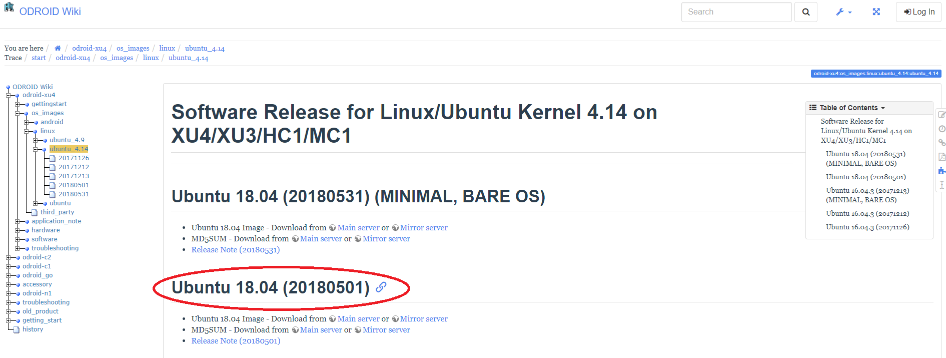
First, download the Ubuntu 18.04 (20180501) operating system from the Hardkernel website at https://goo.gl/ErjTVT. Make sure to wait for the complete download. You can download the image from Hardkernel’s wiki page at https://goo.gl/JYvNGY.
Ubuntu 18 is among us!
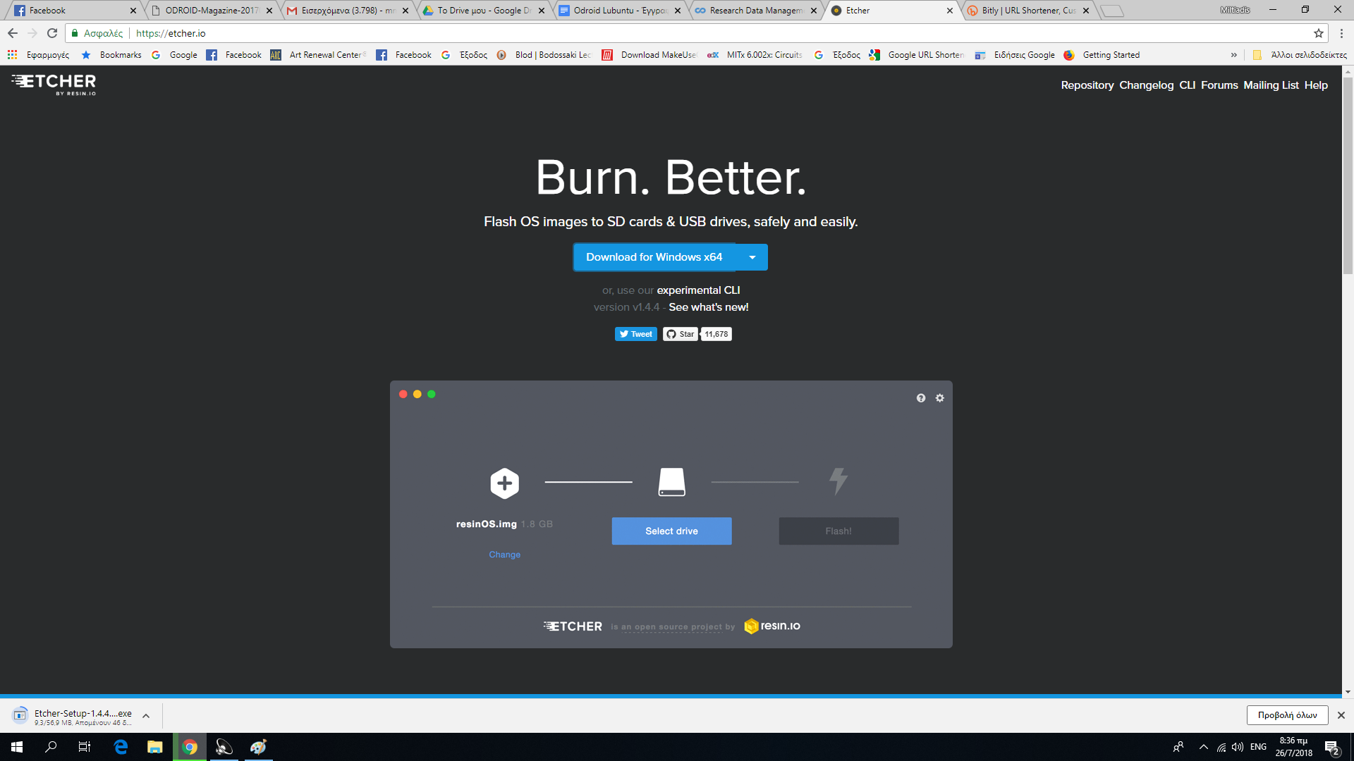
To install, or “flash”, Ubuntu 18.04 to the memory card, we recommend using Etcher, as described at http://bit.ly/2f61k5x. You can download etcher from https://etcher.io/.
Figure 01 - Etcher
Etcher works on Mac OS, Linux and Windows, and is the easiest option for most users. Etcher also supports writing OS images directly from the zip file, without any unzipping required. To install the OS on an eMMC module, you will need an eMMC module reader (https://goo.gl/A5LVTR) and a USB multi reader (http://goo.gl/fMfjZr) to connect it to your PC.
First boot
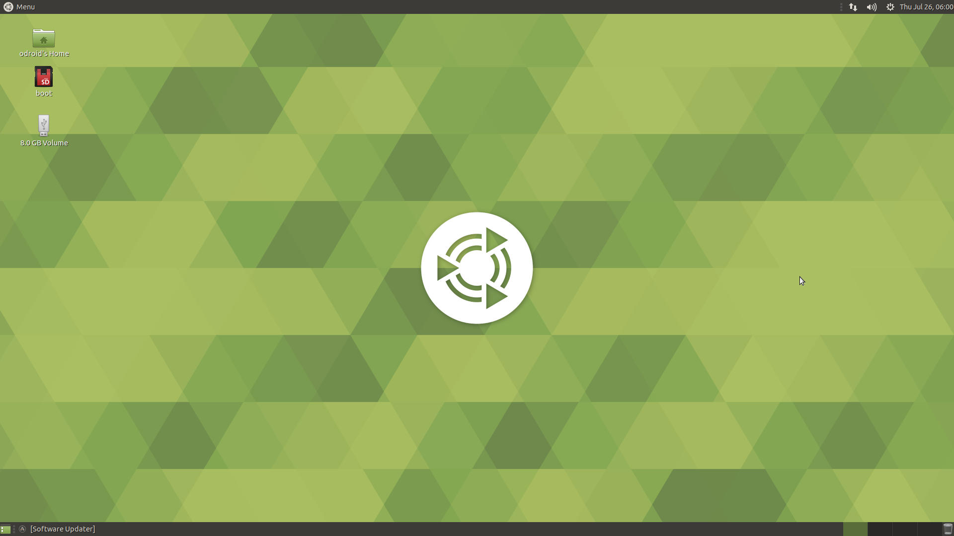
At first boot, “mind the gap”. According to Hardkernel’s Wiki, the RootFS Auto-resize feature has changed. Once everything is done after auto-resize, the power will turn off automatically. Wait a couple of minutes, and press the power button if the blue LED is off. The image boots within 30-40 seconds and Figure 2 shows our freshly Ubuntu 18.04 with Mate desktop.
Figure 02
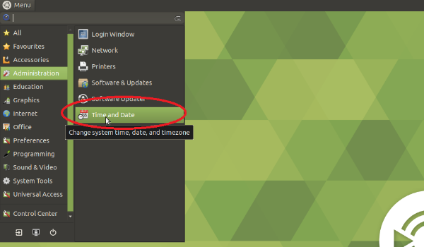
The first thing to do is to adjust the time and date. From the menu, click Administration-->Time and Date, as shown in Figure 3.
Figure 03
Next, update system and kernel software. Do not forget dist-upgrade (the password is “odroid”):
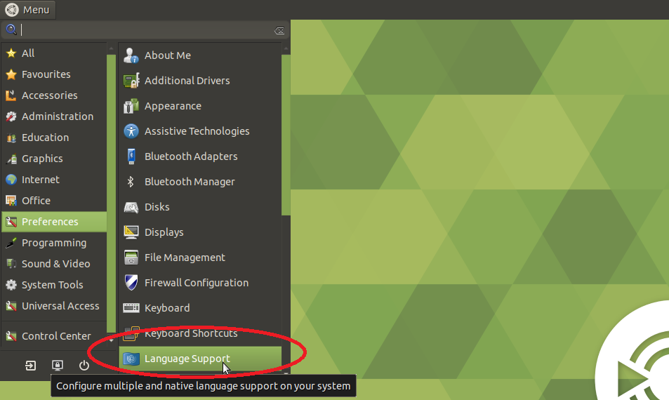
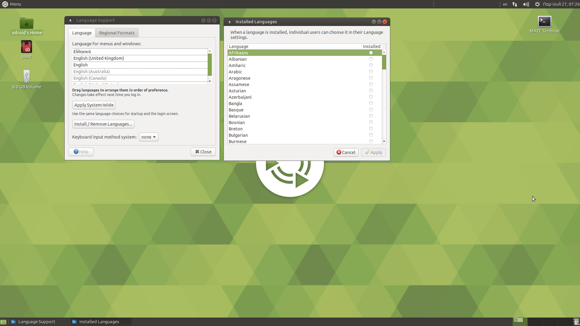
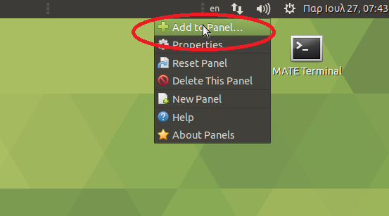
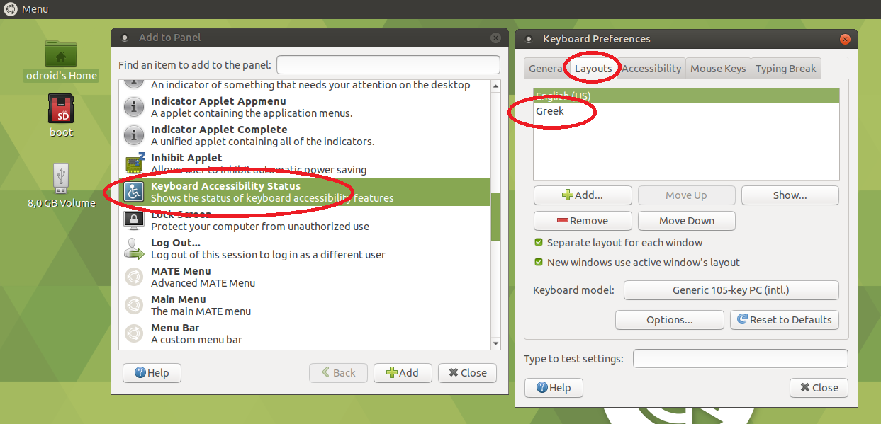
Then, install your preferred language (mine is Greek), and finally add the Keyboard Accessibility Status to the panel, as shown in Figures 4 - 7.
Figure 04
Figure 05
Figure 06
Figure 07
Installing applications and testing performance
Hardkernel’s Ubuntu 18.04 image comes preinstalled with many applications, such as Chromium browser, Thunderbird (email client), LibreOffice, and MPV media player, just to name a few and of course Kodi. Nevertheless, some more are needed for a fully desktop OS experience.
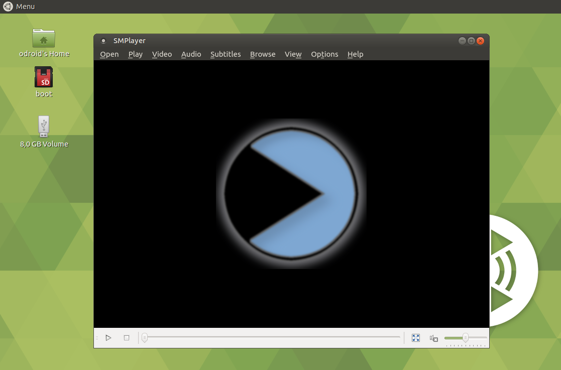
Install SMPlayer, one of the best players in Linux. So from the console just type:
$ sudo apt install smplayer
and then select Menu→ Sound and Video--> SMPlayer from the menu, as shown in Figure 8.
Figure 08
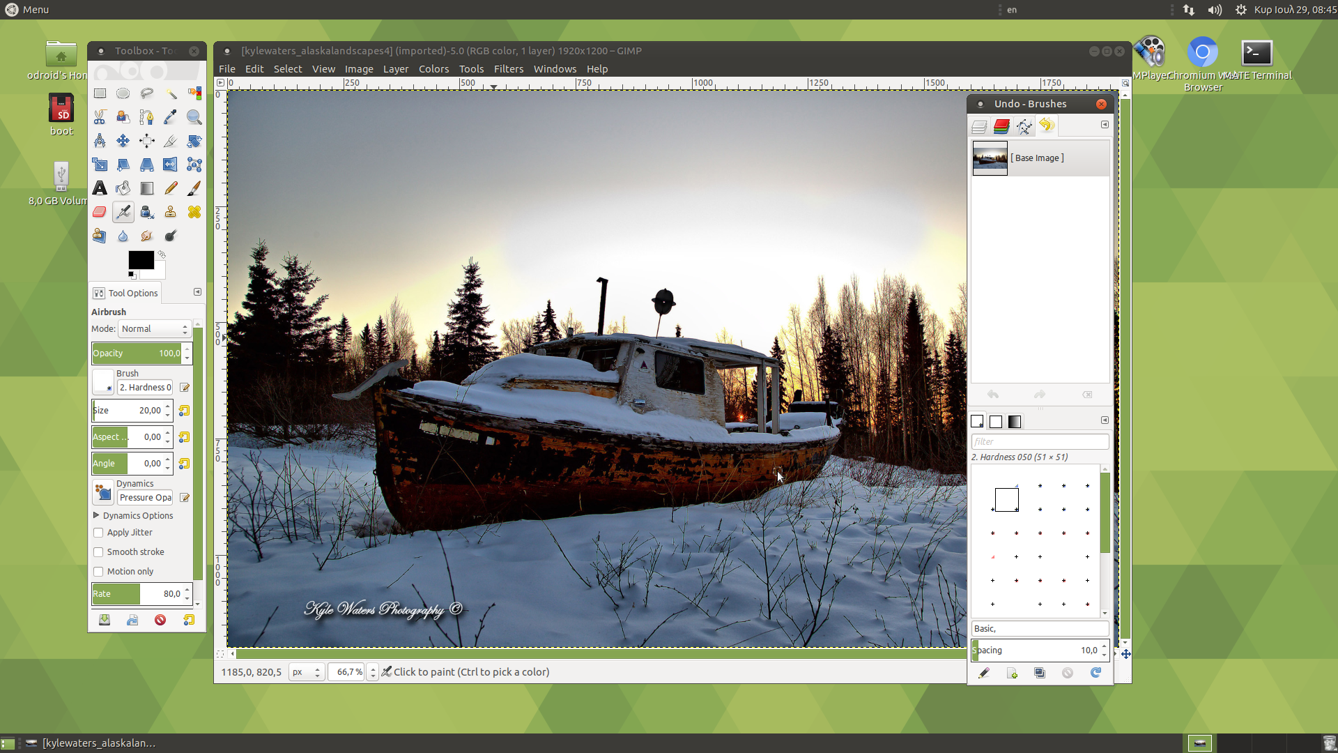
Install GIMP the top graphics editor for Linux, which executes fast and runs well:
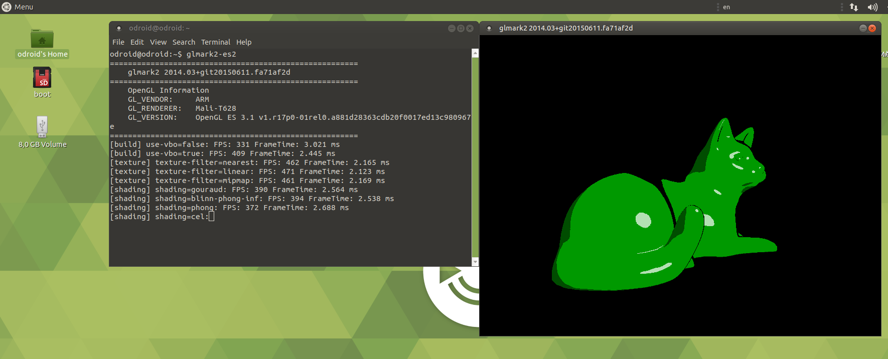
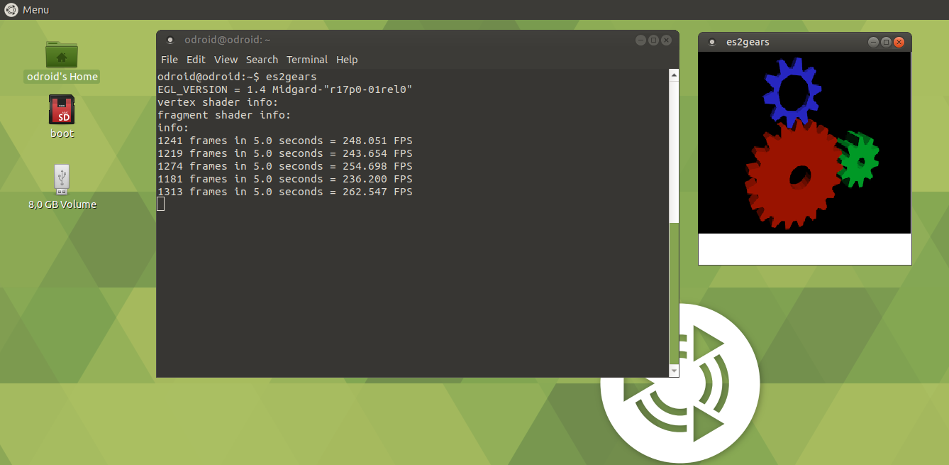
You can also test 3D graphics using glmark2-es2 and es2gears with spectacular results:
$ glmark2-es2
$ es2gears
Figure 10
Figure 11
Finally, we tested the WebGL function within the Chromium browser going to the WebGL sample page at http://webglsamples.org/. We got almost 30FPS with 500 fish in the tank at the aquarium test available at http://webglsamples.org/aquarium/aquarium.html, which is a satisfactory experience for such a “small” board.
Figure 12
Known issues
According to Hardkernel’’s wiki page (https://goo.gl/wuV9Vx) the following issues should be taken into account:
1. Mali GPU access could be blocked by a recent Canonical's EGL package. In that case, you need to install Mali driver manually.
$ sudo apt-get install mali-x11 --reinstall
2. VLC does not start due to a video driver compatibility issue. The reason is that VLC does not support a generic ARM Linux platform well. Recent updates made it even worse. I tried a H.264 file on Kodi and it worked without any problem. However, MPEG4/MPEG2 files do not play well with hardware decoder. I had a lot of crashes. The OS itself has nothing to do with it. It is part of the programs that run on it. Some investigation revealed that Ubuntu 18.04 uses Kodi with hardware accelerated ffmpeg backend rather than the MFC hardware decoder backend from Oversun. The ffmpeg implementation does not seem to run very stable, while the MFC backend in Kodi up to version 17.6 did work pretty well. Older versions of Ubuntu such as the 16.04 image might still use the version of Kodi that uses MFC backend rather than ffmpeg and with that run more stable. We will have to wait until Hardkernel fixes the issue.
3. The first time launching of Chromium takes around one minute due to internal initialization process. After that, it starts in 1-2 seconds.
4. Some UASP capable USB-to-SATA bridge controllers are not compatible. If your external HDD is not working properly, according to Hardkernel, add its VID/PID in boot.ini. Boot arguments to disable the UAS function something like this:
$ usb-storage.quirks=0x0bc2:0x2322:u
5. Change CPU governor to “ondemand”, run this command, and reboot:
$ echo 'GOVERNOR="ondemand"' | sudo tee /etc/default/cpufrequtils; systemctl mask ondemand;
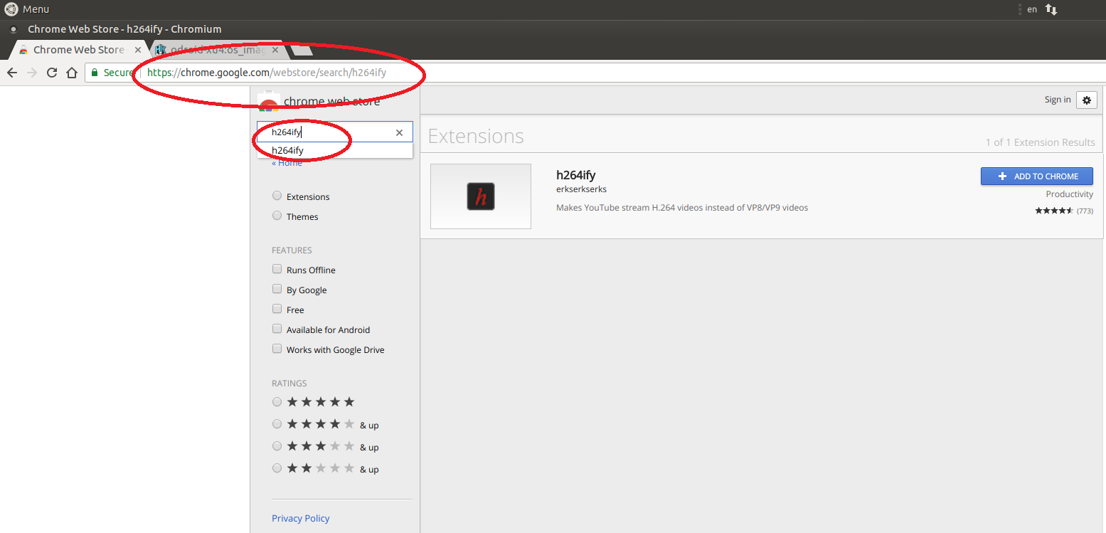
Then, install the “h264ify” extension from the Chrome Web Store for Chrome browser, which can improved the Youtube video quality on Chromium browser can be improved a lot. 720p/30fps videos are fine with the extension.
Figure 13
Advantages
Ubuntu 18.04 OS is quite stable on ODROID XU4. Programs are executed very quickly, and the board offers a pleasant internet browsing. The performance of the board with accelerated 3D graphics working well in demos and some webGL demos. H.264 hardware decoding in Kodi and FFmpeg working well up to 1080p, and Youtube up to 720p, fast program load times thanks to the eMMC flash module (https://goo.gl/r5Zi8M), and decent multi-tasking ability.
As an epilogue, we could say that Ubuntu 18.04 on ODROID-XU4 board was a very satisfying experience, and quite close to that of a desktop computer. Despite some performance issues with playing AVI files, in most cases the system performed well and reliably with fast program loading times. The hardware video coding, 3D graphics acceleration for OpenGL ES and most features working as expected. Give it a try!
Kali Linux 2018.2 On The ODROID-XU4
September 1, 2018By Philipp MorozovLinux, Tutorial
Note to our readers: This article setup is running With A Touchscreen And Alfa AWUS1900 WiFi Adapter Support
Kali Linux is one of the best systems for penetration testing. It is available for various ARM-based devices and for a short time the ODROID-XU4 was available on the official Kali website. Unfortunately, an image is no longer available. This article covers the following things:
How to install Kali Linux 2018.2 on ODROID-XU4
How to get touchscreen recognize multitouch gestures
How to make Alfa AWUS1900 work with ODROID-XU4
Disclaimers
You are taking full responsibility for your actions
This guide is easy to follow, nevertheless, don’t skip any sections that seem easy and read each on till the last one
Make sure to backup your data
Don’t worry about warning messages during the execution of the make command
The author allows anyone to share the material given below, but you must include this article as the source
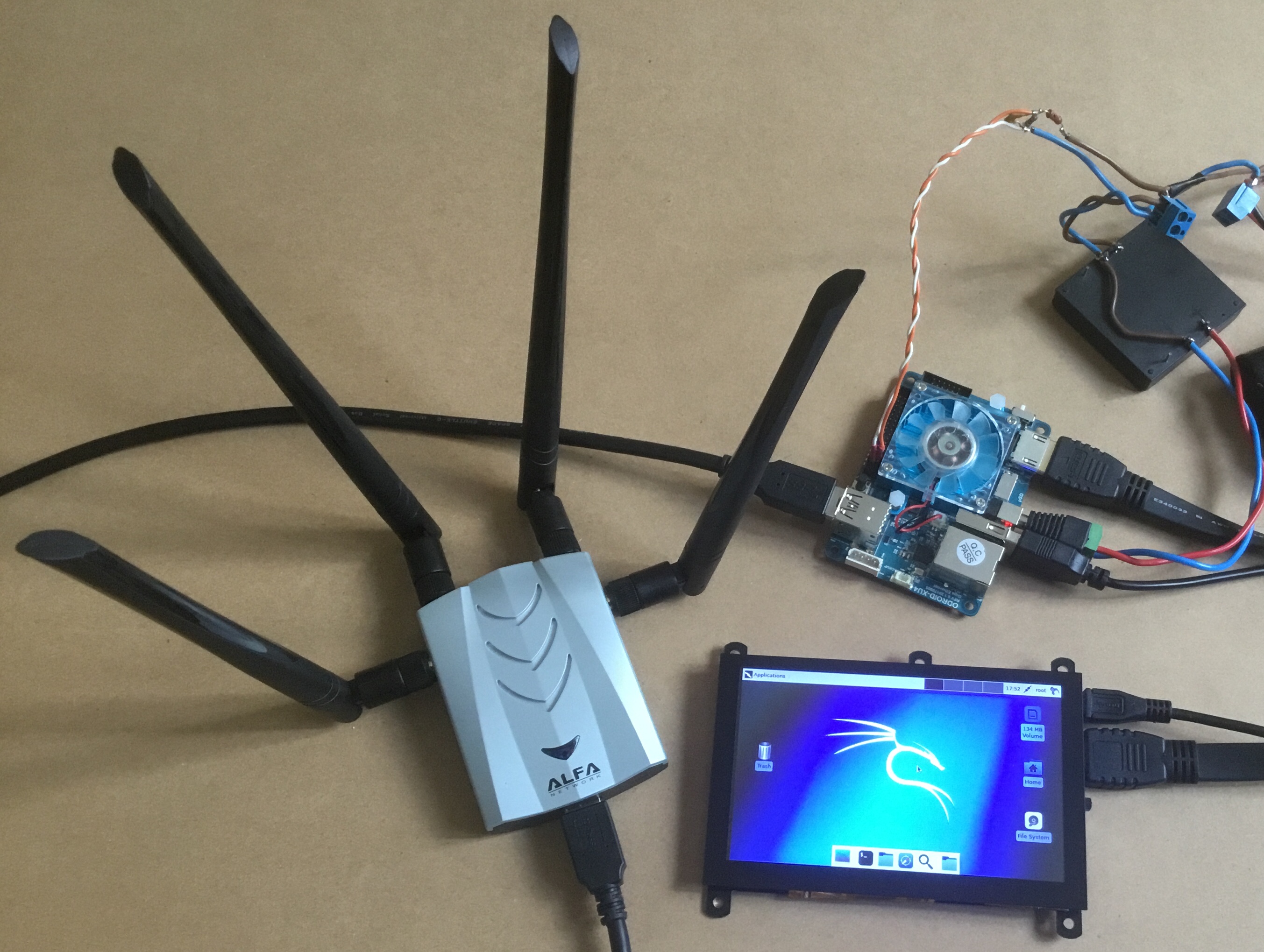
Figure 1 - Kali Linux 2018.2 on ODROID-XU4 with Alfa WiFi adapter connected
Installation
Download the ‘Kali Linux Odroidxu3’ image from the official Kali Linux website: https://www.offensive-security.com/kali-linux-arm-images/ and flash it to a eMMC or microSD. Make sure your XU4 is connected to the Internet. Boot your XU4 and login using using a user of ‘root’ and password ‘toor’. Choose to use the default configuration for the Panel. If you are using a multitouch display, e.g. ODROID-VU5, you will notice, that graphics will appear glitchy and the touchscreen won’t react to touches. Though, USB 3.0 ports should work fine. We are going to compile and update the Linux kernel to v4.14, which will significantly improve the overall performance and fix known faults.
WARNING! If you are using a multitouch display, make sure your XU4 does not go to sleep during the kernel update, otherwise you may not be able to turn it on without rebooting. If your screen starts flickering, it means that the XU4 is about to sleep. You are recommended to temporary increase all three values in [Applications > Settings > Power Manager > Display] to their maximum value.
Launch the terminal and now we are ready to begin preparation. Do the basic process of a software update and then install some packages that are required for further steps:
Now we need to choose proper drivers for the GPU. There is a mali-t62x-x11-driver package available via apt, but the XU4 will have some dependency faults with it. Therefore, we will install the driver from Hardkernel's Ubuntu repository and adapt it to work with Kali Linux:
$ wget -O mali http://deb.odroid.in/5422-s/pool/main/m/mali-x11/mali-x11_20180717-r17p0-a52903b-11_armhf.deb
$ dpkg -i mali && rm mali
$ cd /usr/lib/arm-linux-gnueabihf
$ sos='libEGL_mesa.so.0.0.0 libEGL.so.1.1.0 libGLESv2.so.2.1.0'
$ for so in $sos; do rm -rf $so; ln -s mali-egl/libmali.so $so; done
Now the driver is ready. Remove unnecessary packages and reboot:
$ apt autoremove -y
$ reboot
After the XU4 rebooted, check that the kernel has been updated successfully:
$ uname -r
You should see 4.14.55+. Touchscreen and other modules should be working now. Enjoy your updated Kali Linux on XU4.
Multitouch gesture recognition
Although the touchscreen is now working, it's only capable of handling single touches. Let's teach it to recognize multitouch gestures. There is a tool called ‘touchegg’, that handles multitouch activities, but it has bugs, when it comes to a single touch mode. Therefore, we will install another tool called ‘tatchi’, that will allow us to switch between single (default) and multi (touchegg) -touch modes with just one click. Installing touchegg is a bit tricky, due to its dependencies. So let's get them:
$ apt install netselect-apt libqt4-dev libxtst-dev libxv-dev multiarch-support -y
$mirror="$(echo $(netselect-apt jessie -a armhf -o /dev/null) | awk '{print $1;}')pool/main/g/geis/libgeis"
$ debs='1 -dev'
$ for deb in $debs; do temp=$(mktemp); wget -O $temp $mirror$deb'_2.2.16-1+b1_armhf.deb'; dpkg -i $temp; apt install -f -y; rm $temp; done
Now we are ready to install touchegg:
$ git clone https://github.com/JoseExposito/touchegg
$ cd touchegg
$ qmake
$ make
$ make install
Now we need to install tatchi:
$ git clone https://github.com/mopo3ob/tatchi
$ cd tatchi
$ make install add
$ cd ../..  && rm -r touchegg
A hand icon should appear in the top-right corner, of the panel. Tap it once to switch to multitouch mode. The icon will now change from one pointing finger to two fingers. This means, that touchegg is ready for recognizing multitouch gestures. Try to scroll the terminal with two fingers. Tap the hand button once again, to switch back to single touch mode. It’s as simple as that.
You will probably want to customize the configuration for multitouch gestures. You can do so by editing ~/.config/touchegg/touchegg.conf. Explore touchegg's wiki for more information: https://github.com/JoseExposito/touchegg/wiki.
Configuring the Alfa AWUS1900 WiFi adapter
Now that we have a fully operational XU4 running the latest release of Kali Linux, it’s time to get our hands on the Alfa AWUS1900, which is considered to be the best WiFi adapter available for penetration testing. The AWUS1900 allows router connection speeds of up to 1900 Mbps, which requires an USB 3.0 port. The ODROID-XU4 is one of the few microcomputers that can use such a powerful quad antenna. To get it working we only need to install the driver for the Realtek RTL8814U chipset, which is the chipset AWUS1900 adapter uses.
$ git clone https://github.com/aircrack-ng/rtl8812au -b v5.2.20
$ cd rtl*
$ make ARCH=arm
$ make install
$ cd ..  && rm -r rtl8812au
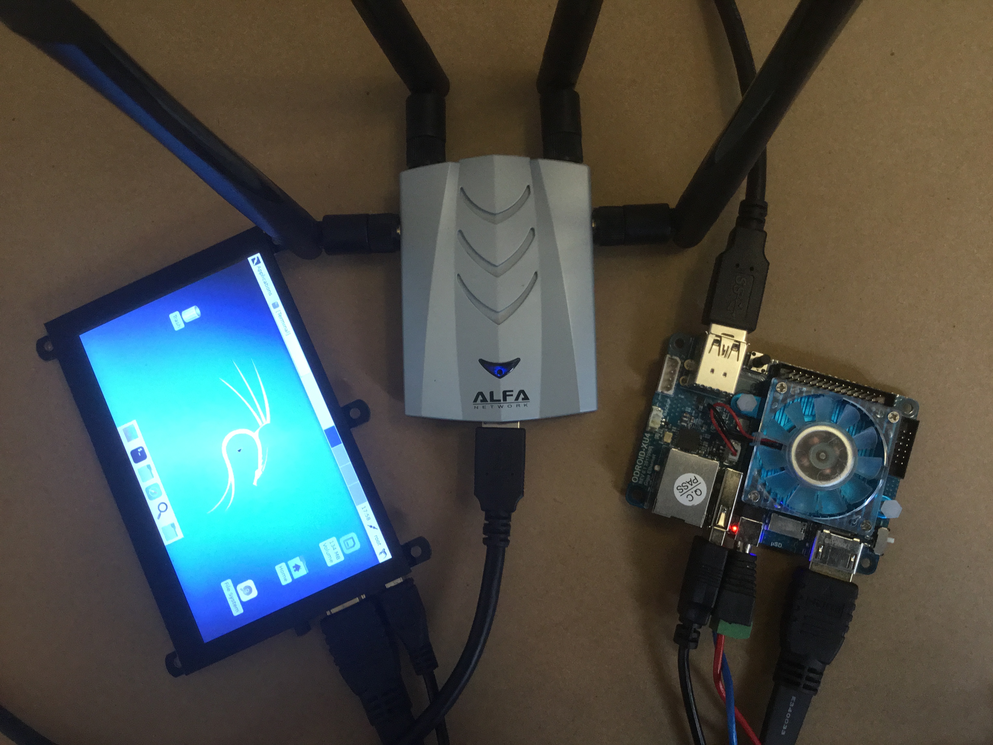
Driver installation is completed. Plug in your AWUS1900 and a blue led indicator will turn on.
Figure 2 - Blue led indicator on Alfa AWUS1900 WiFi adapter
Now let’s uses ifconfig with our AWUS1900:
$ apt install net-tools
$ ifconfig
You are now able to see wlan0, provided that you are using an Ethernet cable for the Internet. To put AWUS1900 in monitor mode manually, execute following commands:
$ airmon-ng check kill
$ ip link set wlan0 down
$ iw dev wlan0 set type monitor
$ ip link set wlan0 up
$ service NetworkManager restart
Give it a test by scanning for hotspots:
airodump-ng wlan0
It shall be able to detect nearby hotspots. Send ^C (Control+C) to stop scanning.
We now have one of the most powerful microcomputers running Kali Linux 2018.2 and working with an ODROID touchscreen and Alfa AWUS1900. Thanks to @odroid, @robroy and @mad_ady for helping me to find solutions to the questions covered in this article.
Using ODROIDs in High Performance Computing (HPC) – ARM: Head and Shoulders Above The Competition
September 1, 2018By Kurt Keville, MITMathematics
A modern datacenter uses far too much electricity and air conditioning to run efficiently. An ARM-based Internet Service Provider can deliver web pages for substantially less power than conventional architectures (http://tinyurl.com/ApacheOnARM). At the same time, ARM cores are rapidly being adopted by the scientific Datacenter community because ARM devices compute faster in floating-point math intensive operations, for a fraction of the energy costs, and have an architectural roadmap of even more performance per watt to come. There is also a corresponding growth in interest in HPC (High Performance Computing) and its uses in broader domains from the ARM developer community. In academia, there is also High Performance Extreme Computing (http://www.ieee-hpec.org/) and IEEE Supercomputing, which were demonstrated at the recent SC13 conference in Denver, Colorado. Additionally, IEEE Cluster, which was held in Indiana in 2013, has seen a marked rise in ARM-centric publications.
The majority of modern supercomputing centers have thousands to tens of thousands of cores dedicated to their particular processing needs. Any time a programmer can run an application at an improved performance ratio (per watt, dollar, or square meter) is a win to the Datacenter stakeholders as well as the computationally scientific domain customers they support. This is increasingly the case for situations where applications must be run multiple times, and where multiple applications share resources in HPC, a lot like the cloud and a throwback to old-style timesharing.
Why ARM?
The ARMv7 architecture has proven to be up to the challenge of HPC in a number of ways that previous ARM architectures were not. One might use ARM despite energy efficiency as the technology represents a growth path for fast embedded computing. When a Datacenter is composed of over 10,000 cores, considerable advantages are realized through incremental improvements. These small changes can add up to significant savings in space, power, and cooling. When memory is shared between the CPU and the GPU on ARM SoCs (System on a Chip), double the SIMD (Single Instruction, Multiple Data) extensions on Cortex-A15 NEON GPU, and considerably larger memory access potential, benefits are realized at the place we need them most; where the application and data sets meet on-die. With growing acceptance of GP-GPU (General Purpose GPU) computing and expansion of HPC-type applications based on big data apps, the fast computing modes of ARM are relevant in more ways than ever, with a technology path towards an ever-expanding share of HPC.
Why ODROID?
Today, ODROID has an Exynos family processor and at least 4 ARM cores. The upcoming Exynos5 series has 8 cores, 4 of which are ARM Cortex-A15. Hardkernel, as well as the RunTime Computing Solutions research consortium, have demonstrated substantial power and performance improvements of the XU in comparison to other contemporary architectures. With Hardkernel’s ambitious release schedule of new technologies, adopters of this platform follow Moore’s law and ARMs rollout efficiently, allowing them to join the wave of newer, better, lower cost, higher performance systems as they emerge with meaningful upward compatibility.
What’s more, Cortex-A15 wins on most ARM-HPC benchmarks (for instance, the NAS Parallel Benchmarks at http://tinyurl.com/ODROID-HPC). The RunTime Computing Solutions team has recently demonstrated pivotal advantages of the A15 over the A9 on the HPCC Challenge, the preferred benchmark for HPC (http://hpcchallenge.org/). This test uses just the A15 cores on the Exynos 5410 and maintains them at maximum capacity during the test (http://tinyurl.com/ODROID-LINPACK) which is not a completely equitable comparison. However, meaningful information can still be gleaned from it; XUJessie is twice as good as U2Whisper in G-HPLINPACK, the first test. The authors demoed the SOX BOX at SC13 featuring many hardware mods which improved performance. See our sites for more info.
Conclusion
Today we can run many HPC applications on ODROID, and as the upward pressures of energy efficiency cause industry professionals to rethink Datacenter design, progressively more centers will adopt these architectures. The future is bright for designers as the push towards exascale computing ushers in a new and exciting theme in embedded SoC technologies.
Meet An ODROIDian: Andrew Armstrong
September 1, 2018By Rob RoyMeet an ODROIDian
Please tell us a little about yourself.
I am the CTO and co-founder of Cadonix, the world's first fully browser based cloud electrical CAD solution. I have a broad range of expertise ranging from scientific research, embedded systems, electronic design, software engineering and manufacture. I am very fortunate as this allows me to work with some of the most interesting companies in the world on their exciting new technologies. In equal measure I get a lot of enjoyment from the budding community of electronics, computer and gaming enthusiasts I meet through my YouTube channel, where I work on a lot of electronics projects.
I live in rural Oxford in the UK. It is a great location for a technology company as its not only near to London, but also one of the key scientific hubs in the UK, especially for our burgeoning space and electric vehicle industries. There are a lot of clever people around here if you go looking!
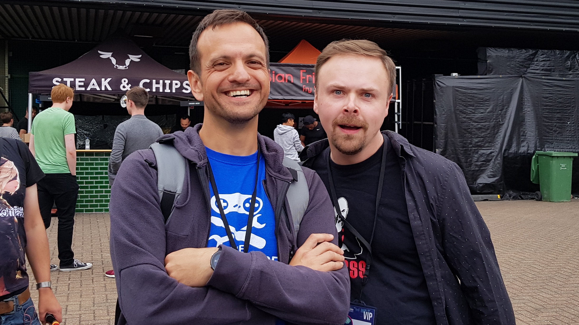
(Figure 1 - Stuart Ashen (aka Ashens http://www.youtube.com/ashens) is a famous Youtuber, gamer and movie producer / star. This was at the PLAY EXPO London 2018. We were chatting about the ODROID-GO as Stuart loves reviewing gaming hardware and is most known for his review and movie about the “Gamechild”)
By most measures, I was a pretty average high school student (probably below average) who did not get high enough grades for my chosen university. Fortunately enough, I plucked up the courage to visit them in person and ended up on a Software Engineering degree course that I completed with a 1st Class Honors degree. It did not stop there though, since the University kindly sponsored me their Doctorate program, and a few years later I ended up with a Ph.D., specifically in the field of Image Compression. I went on to a Postdoctoral Research Fellowship in Loughborough University after that to work on H.264 video compression. Around 5 years later, I was accredited as a Chartered Engineer. I always encourage people to keep trying and find that thing they are really passionate about. For me it was, and still is, learning!
(Figure 2 - Heyford Air Base 10K 2018 - Dr A and Coach Ali Gilbrath smashing their personal bests for the 10k)
Figure 3 - Kids Heyford Air Base 10K 2018 - My two young sons Alex and Theo also partook and won medals in their category, which was the proudest day of my life!
I live with my two young boys Alex and Theo, my wife Sarah and our cat Ziggy. Sarah works at Oxford Brooks University helping to steer young minds on the right educational path. It can get hectic at times because I have a lot of international travel as part of my role, but we find ways of making it work with supportive family reasonably close.
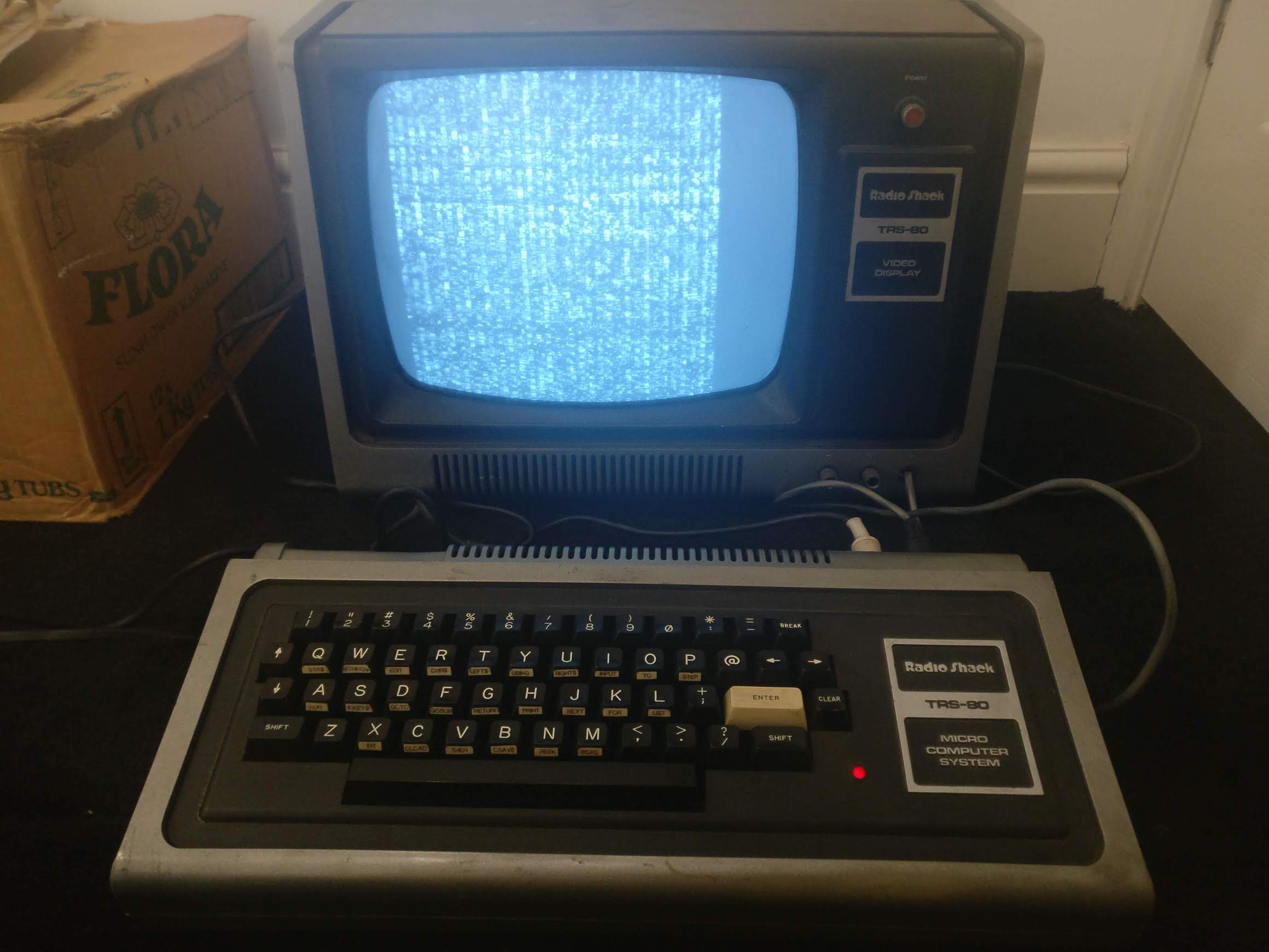
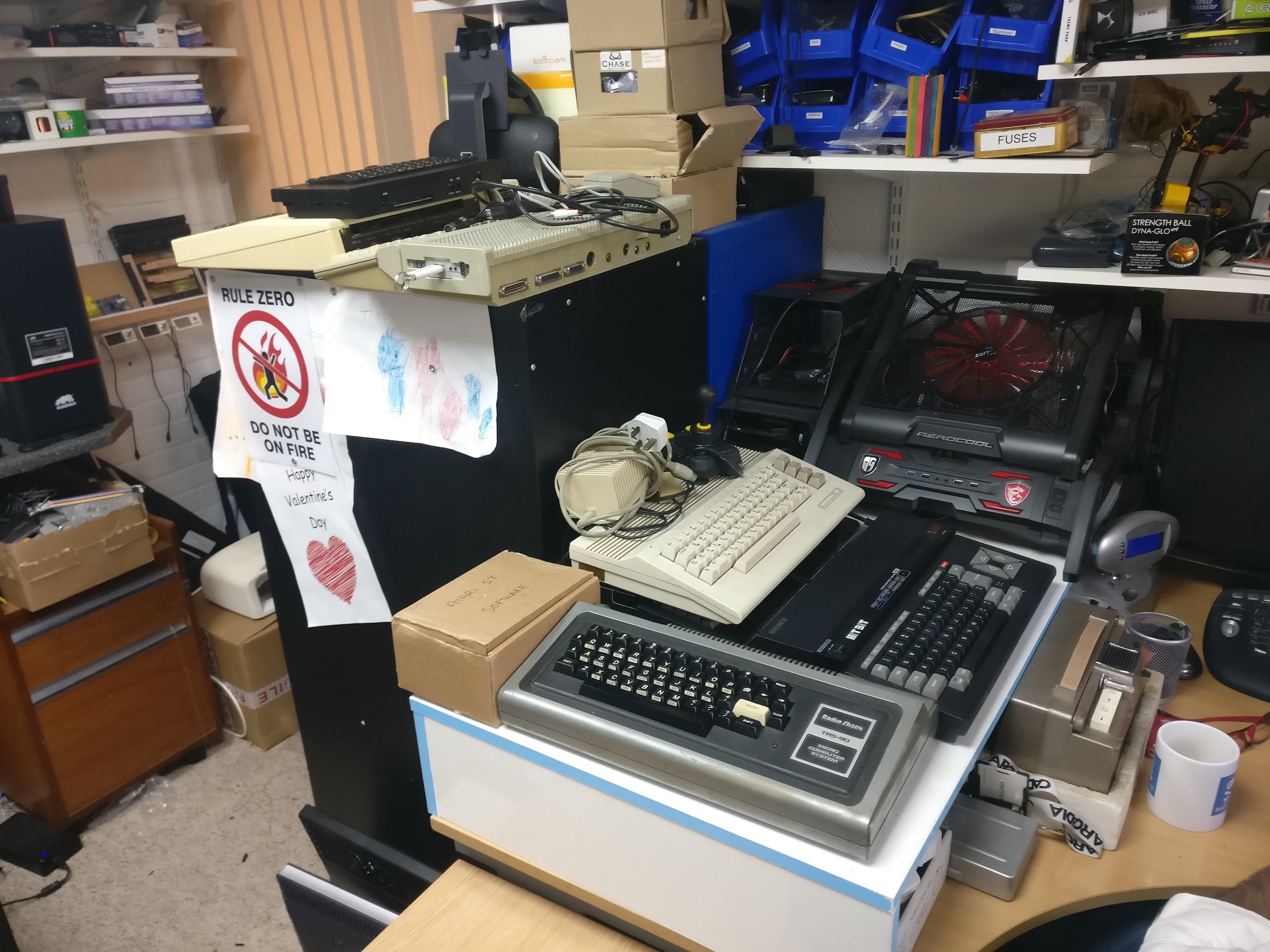
How did you get started with computers?
I was first introduced to computers at the age of 3. It was a TRS-80 that my father, who worked for ICL at the time (the UK's version of IBM), had purchased from a friend. I remember patiently watching the asterisk in the corner of the screen flashing while waiting for a cassette tape player to load my favorite pastime, Dancing Demon. After that it was a progression of 8 bit and 16 bit computers and consoles over the years ranging from BBC Micro, Commodore 64, Atari ST, PC, Apple Macs etc.
Figure 4 - Neil from the retromancave is another Youtuber on handhelds and old computers, and we both host a podcast called Retro Island Diskettes
Figure 5 - Jarad and Back to the future Sneaker - Jarad is a maker friend, we are posing next to a remake of the legendary Back to the Future Nike sneakers
Probably the most pervasive machines we had in our households were the various PCs that always existed in my background, be it the humble IBM AT or the exotic Compaq Portable III they were probably the bedrock of my computing. It is safe to say that I learned to program every machine I owned.
What attracted you to the ODROID platform?
I am a little embarrassed to say that I have been relatively in the dark about the ODROID hardware until recently, favoring their ubiquitous cousins in projects. However, I am really interested in getting into the ODROID-XU4 as a base for future projects. I go through a lot of single computer boards, so it’s important to find the right balance of power and support and my recent involvement in the ODROID community has given me the confidence in the platform.
Figure 6 - Design Stream Rig - This is the rig I setup to record the various ODROID-GO videos where we designed and built the first prototype audio hats
How do you use your ODROIDs?
I use my ODROIDs for gaming! Who does not love to fire up some old emulators and play some of the old titles of their childhood? It’s easy to see this as a pretty trivial use of sophisticated technology, but I think it’s an amazing use case in that it has encouraged so many people to take an interest in hardware and even build their own arcade cabinets.
Figure 7 - Odroid Audio Hard - Some of the first batch of units that I assembled myself
Figure 8 - Built Odroid Audio Hats - Closeup of the hand assembled v1 boards
On the more serious side, I do a lot of embedded electronics, especially in the area of monitoring, data acquisition and control. Many of these are in the automotive industry where performance is key, especially in the development of the most ground-breaking vehicles devised. I am really interested in exploring how to leverage the hardware for this. I am even building a data acquisition interface for the ODROID-GO, as it’s such a great portable unit.
Figure 10 - My first Computer TRS-80 - My very first computer, recently retrieved from an attic and in a poor state, I have changed the memory chips but it needs a little more TLC!
Which ODROID is your favorite and why?
I really like the ODROID-GO! From first seeing it, I just had to have one, so I pre-ordered it immediately. I was very lucky as I received my unit the very next day and eagerly built it. There are two reasons why I really like the platform: 1) you can play games on it, and the first use case for me was to play games while hopping from airport to airport, and 2) you can hack the hardware. I have a popular video out on how to hack in an analogue headphone socket for your ODROID-GO, which is a bit of an omission for those of us who want to use it in public places. I recently started following the forums, and in a series of Live YouTube streams the backoffice community designed a solder-free upgrade to add this capability to the GO. The community working on the ODROID-GO firmwares are doing great things, especially people like crashoverride who ceaselessly works on improving the platform. Clearly hacking the hardware and coming up with solutions with internet friends is an amazing amount of fun and a big draw to the platform.
Figure 11 - A rare glimpse of some of the machines that are hiding in the Backoffice: how many can you see?
What innovations would you like to see in future Hardkernel products?
This is a tricky one, since Hardkernel seems to be innovating like crazy, and I’m having trouble keeping up. However, I would really love to see an automotive interface board and really nice enclosure. I know a lot of people who are either trying to build (or get me to build!) vehicle diagnostic tools using CAN bus and LIN bus, or people who are trying to build entertainment or control system for vehicles. There is a huge market for people who want to modify their vehicles, and a tried and tested platform would really help.
Figure 12 - I like to hack old computers and see if I can build interesting interfaces to them. I will be using my ODROID-GO to transfer data to and from this Amstrad CPC soon
What hobbies and interests do you have apart from computers?
Anyone who watches my YouTube channel or is on my Discord group will know that get bored easily, and hobbies seem to come and go monthly. My most enduring ones are motorcycling, working on my cars, and running. The latter engages with the scientist in me as I absolutely love the data you get from running gadgets, from how much weight you are putting on your left leg to how hard your heart is working.
Figure 13 - One of the summer projects was to learn how to make t-shirts, which is a lot of fun and a pretty technical process you need to expose the screen to UV to transfer your design
What advice do you have for someone wanting to learn more about programming?
If someone came to me fresh with zero programming knowledge I would tell them to really learn the fundamentals. To really be a great software engineer, you really need to understand how the hardware works. You may decide that you are going to be a web programmer, but those fundamentals of getting your code running on bare metal will help you through your career, so start with a calculator!
If they could grab an old micro-computer like a BBC Micro, Commodore 64 or Amstrad CPC, and work their way through the basic and advanced programming guides, I think they would be in good stead to move onto the flavor-of-the-month PC languages. Barring that, I would say to download Lua or one of the packaged environments. It has to be my favorite language of all time in terms of teachability and ease of use. It has the simplicity of BASIC, but offers nearly limitless power in the right hands; just check out what people are doing with PICO-8.
Figure 14 - I never let the opportunity to make a silly face for social media go to waste!