


Two use cases are presented in this article that are of special interest to those building car computers using ODROIDs. The first is to stream audio via Bluetooth A2DP from an iPhone to an ODROID-XU4, and the second is to use the ODROID-XU4 as an HFP Handsfree Unit for the iPhone during calls. We will be using the Bluez 5 bluetooth stack, the oFono mobile application development framework and the PulseAudio sound system software for this project. Although I have not tested it, this procedure should work with an Android phone.
A2DP is very easy to setup and is completed on the way to setting up handsfree. HFP is more difficult to setup because it requires building PulseAudio 11 from source and replacing the PulseAudio 8 package preinstalled in Ubuntu MATE. I have divided this article into two sections so that those of you only interested in A2DP can avoid the more difficult steps in getting HFP to work. If you are only interested in the Bluetooth speaker functionality, you can use the ODROID-XU4's built-in audio out over the HDMI port instead of the C-Media CM108-based USB audio adapter. To keep things simple, this article assumes you will be using the USB audio adapter listed below.
Before you start, note that documentation and discussions for the latest versions of Bluez 5, oFono, and PulseAudio are somewhat sparse. Most of everything I found online for this project's use case was too old, discussing prior versions of each software. If you run across a problem trying out this project, there is a fairly high chance you will not find anyone knowledgeable enough to help, myself included! I advise you to not stray too far from these instructions and hardware selection until you have gotten your setup working properly, then you can get creative knowing you have a working baseline to go back to.
Phase 1: A2DP
A2DP can be accomplished using the packages preinstalled with Ubuntu 16.04.3 MATE: Bluez 5.37, oFono 1.17, and PulseAudio 8. Start with an ODROID-XU4 running the official Ubuntu 16.04.3 with 4.9 kernel MATE image and run all the OS updates before starting this project. I used the ubuntu-16.04.3-4.9-mate-odroid-xu4-20170824.img image file. You are probably better off choosing the ODROID-XU4 instead of the ODROID-XU4Q, since the extra CPU performance may help reduce call audio latency or improve audio quality if you decide to go further and optimize PulseAudio's resampling.
The specific devices I used for this project are:
- iPhone 5S
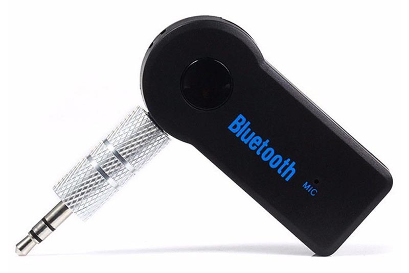
- Cambridge Silicon Radio Bluetooth USB adapter: http://bit.ly/2gNybJW.
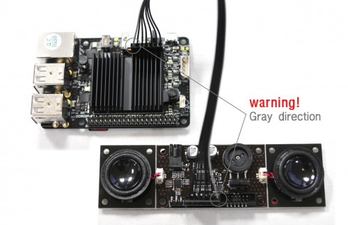
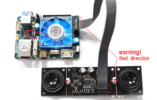
- Sanwu Audio SW-HF07 USB audio adapter (with a C-Media CM108 chipset that is known to work on ARM LINUXes with the built-in driver): http://bit.ly/2zEBIWZ.
- Headset with separate 3.5mm microphone and headphone plugs for testing

Insert the USB Bluetooth and audio adapters into available USB ports on the ODROID-XU4, then insert the headset's headphone and microphone plugs into the corresponding jacks on the audio USB adapter.
Selecting the correct audio interface
Log in to the MATE desktop as the default user “odroid”. This step is important because PulseAudio is setup to run in per-user mode by default, so it will start automatically after you log in but is not running when the logon screen is being displayed. We will not be setting up PulseAudio to run in system-wide mode in this article, as it introduces extra challenges.
Test the audio using the built-in Sound Preferences application in MATE. Change and save the configuration as necessary, testing the sound as needed. Since I am using a C-Media USB audio adapter, I had to select it as the default Input and Output device as opposed to the ODROID-XU4's built-in audio (output through the HDMI port). Leave the Sound Preferences application open so that PulseAudio is running in your user session.


In the /home/odroid/.config/pulse directory, look for the files ending in “-default-sink” and “-default-source” and write down the filenames and their contents. You should see something like this:
dc87f36fc06c441a85ff7269baabcdef-default-sink:
 alsa_output.usb-C-Media_Electronics_Inc._USB_Audio_Device-00.analog-stereo

dc87f36fc06c441a85ff7269baabcdef-default-source:
 alsa_input.usb-C-Media_Electronics_Inc._USB_Audio_Device-00.analog-mono
You want the selected device in both files to be the audio interface that has the microphone, which is typically not the built-in HDMI audio output. Use the Sound application to test the audio input and output before moving on to the next step.
Bluetooth pairing with your iPhone
Bluez 5.x is already preinstalled in the Ubuntu 16.04.3 MATE image, so all we have to do is pair your iPhone to the ODROID-XU4. We will use the included bluetoothctl command, which must be run with root privileges, or it will error out:
$ sudo -s
# bluetoothctl
 [bluetooth]# show
You should see something like this:
Controller 00:AA:BB:CC:DD:11
 Name: odroid
 Alias: odroid
 Class: 0x1c0000
 Powered: yes
 Discoverable: no
 Pairable: yes
 UUID: Headset AG (00001112-0000-1000-8000-###########)
 UUID: Generic Attribute Profile (00001801-0000-1000-8000-###########)
 UUID: A/V Remote Control (0000110e-0000-1000-8000-###########)
 UUID: OBEX File Transfer (00001106-0000-1000-8000-###########)
 UUID: Generic Access Profile (00001800-0000-1000-8000-###########)
 UUID: OBEX Object Push (00001105-0000-1000-8000-###########)
 UUID: PnP Information (00001200-0000-1000-8000-###########)
 UUID: A/V Remote Control Target (0000110c-0000-1000-8000-###########)
 UUID: IrMC Sync (00001104-0000-1000-8000-###########)
 UUID: Audio Sink (0000110b-0000-1000-8000-###########)
 UUID: Audio Source (0000110a-0000-1000-8000-###########)
 UUID: Vendor specific (00005005-0000-1000-8000-###########)
 UUID: Message Notification Se.. (00001133-0000-1000-8000-###########)
 UUID: Phonebook Access Server (0000112f-0000-1000-8000-###########)
 UUID: Message Access Server (00001132-0000-1000-8000-###########)
 Modalias: usb:v1D6Bp0246d0525
 Discovering: no
If PulseAudio was not running, the list of profiles would be much shorter.
If “Powered” is not “yes”, type the following command:
# power onNow, let us start pairing by scanning for nearby devices:
# scan onOn your iPhone, go to Settings > Bluetooth and make sure it is turned on and discoverable. You will eventually see your iPhone show up in the scan by its Bluetooth MAC address. Write this MAC address down as you will use it repeatedly in place of [MAC] below.
# scan off
# agent KeyboardOnly
# default-agent
# pair [MAC]
This might fail; try again until it succeeds in initiating the pairing and asks for the passkey. Look on your iPhone for the passkey and input it when it says:
Attempting to pair with [MAC]
 [CHG] Device [MAC] Connected: yes
 Request passkey
 [agent] Enter passkey (number in 0-999999): ######

# connect [MAC]
# trust [MAC]
# info
You should see details on your iPhone and its Bluetooth profiles. On your iPhone, it should show that the device called "odroid" is connected.
# exit


Phase 2: HFP
The next step is to install Ofono 1.17.x for the handsfree Bluetooth profile, since it is not preinstalled with the OS image. Assuming that we are still in the same “sudo -s” session, type the following command:
# apt-get install ofonoCheck to see that the Bluetooth profile has been added:
# bluetoothctl
 [bluetooth]# show

Controller 00:AA:BB:CC:DD:11
 Name: odroid
 Alias: odroid
 Class: 0x3c0000
 Powered: yes
 Discoverable: no
 Pairable: yes
 UUID: Headset AG (00001112-0000-1000-8000-###########)
 UUID: Generic Attribute Profile (00001801-0000-1000-8000-###########)
 UUID: A/V Remote Control (0000110e-0000-1000-8000-###########)
 UUID: OBEX File Transfer (00001106-0000-1000-8000-###########)
 UUID: Generic Access Profile (00001800-0000-1000-8000-###########)
 UUID: OBEX Object Push (00001105-0000-1000-8000-###########)
 UUID: PnP Information (00001200-0000-1000-8000-###########)
 UUID: A/V Remote Control Target (0000110c-0000-1000-8000-###########)
 UUID: IrMC Sync (00001104-0000-1000-8000-###########)
 UUID: Audio Sink (0000110b-0000-1000-8000-###########)
 UUID: Audio Source (0000110a-0000-1000-8000-###########)
 UUID: Handsfree (0000111e-0000-1000-8000-###########)
 UUID: Vendor specific (00005005-0000-1000-8000-###########)
 UUID: Message Notification Se.. (00001133-0000-1000-8000-###########)
 UUID: Phonebook Access Server (0000112f-0000-1000-8000-###########)
 UUID: Message Access Server (00001132-0000-1000-8000-###########)
 Modalias: usb:v1D6Bp0246d0525
 Discovering: no
Note that we now have the Handsfree profile (5th from the bottom of the UUID section of the list). Next, quit bluetoothctl:
# exitAt this point, it is possible to start a phone call with the iPhone Phone app and select the "odroid" device as the handsfree audio, and you will hear the keypad tones as you dial the call, but as soon as the call starts, the ODROID-XU4 will drop the audio and cause the iPhone to switch from "odroid" to its internal speaker and internal microphone.
Here is where a little experimentation is required. The Ubuntu-packaged PulseAudio 8 apparently has a bug or is missing a feature that causes the call audio to drop and fills /var/log/syslog with these error messages (visible if you set PulseAudio to debug logging):
D: [bluetooth] module-loopback.c: Requesting rewind due to end of underrun.
I: [alsa-sink-bcm2835 ALSA] module-loopback.c: Could not peek into queue
The solution is to uninstall PulseAudio 8 and then build and install PulseAudio 11.1 (the latest version as of this writing) from source code, as detailed below.
You should still be in the same “sudo -s” session after running bluetoothctl. If not, type the following command:
$ sudo -sYou might want to make a backup of the PulseAudio autostart file here to be reused later:
# cp /etc/xdg/autostart/pulseaudio.desktop ~
# apt-get remove pulseaudio
# apt-get autoremove
# dpkg --purge pulseaudio
It might be a good idea to remove the old PulseAudio config folder:
# rm -fr /etc/pulsePulseAudio 8 has now been removed, so now we get and build and install PulseAudio 11.1:
# apt-get build-dep pulseaudio
# apt-get install git
# exit
$ cd ~
Get the source code with git using one of the two commands below:
$ git clone git://anongit.freedesktop.org/pulseaudio/pulseaudioor:
$ git clone http://anongit.freedesktop.org/git/pulseaudio/pulseaudio.gitPulseAudio is also released in compressed archives if you do not want the development version in the git repository.
$ cd pulseaudio
$ export CFLAGS=-fomit-frame-pointer
$ ./autogen.sh
$ make
The build will take about 15 minutes and will issue a lot of warnings, but should end without any major errors. If the build went well, and it should, you may install PulseAudio.
$ sudo make installNote that PulseAudio built from source places its config files in /usr/local/etc/pulse, not in /etc/pulse as the Ubuntu-provided PulseAudio does.
There is one setting we will enable in PulseAudio's config file to allow the mono microphone to be remixed to stereo. If not done, the microphone audio will be discarded.
$ sudo vi /usr/local/etc/pulse/daemon.confUncomment the following line by deleting the semicolon in front of it and save the file:
enable-remixing = yesYou must reboot the ODROID-XU4 and log back in as the odroid user now, otherwise PulseAudio will misbehave and cause crackling on the microphone audio. Rebooting will cause the iPhone to lose its Bluetooth connection to the ODROID. Next, you can start PulseAudio (without the benefit of the scripts that automatically started it on logon):
# pulseaudio --start -DAt this point, you should be able to route the call audio to the ODROID. Reconnect your iPhone to the "odroid" device by going to Settings > Bluetooth and tapping "odroid" in the list of paired devices.
Start by playing some music using the iPhone's iTunes. Then, place a call and hear the audio from the call through the ODROID. The final test is to speak through the microphone and have the other side confirm they can hear you.

Finishing up
Note that some of the features of the Ubuntu-provided Sound panel are now broken because we built and installed PulseAudio from scratch. Notably, the "Test Speakers" utility on the Hardware tab does not seem to work any more, and you will not hear MATE UI sound effects. Yet, I was still able to visually monitor the microphone input on the Input tab and adjust the volume using the Volume slider in the system tray. Setup PulseAudio to start automatically in per-user mode by creating this file (or copy the old one back in place, a process I did not test):
/etc/xdg/autostart/pulseaudio.desktop

[Desktop Entry]
 Version=1.0
 Name=PulseAudio Sound System
 Comment=Start the PulseAudio Sound System
 Exec=start-pulseaudio-x11
 Terminal=false
 Type=Application
 Categories=
 GenericName=
 X-GNOME-Autostart-Phase=Initialization
 X-KDE-autostart-phase=1
 NoDisplay=true
Reboot the ODROID-XU4 and log in as the “odroid” user, then make sure PulseAudio is running before reconnecting your paired iPhone.
Troubleshooting
The above procedure has been tested carefully several times, so I did not cover a lot of troubleshooting here. If something does go wrong, I have found that these simple steps often work to set things right:
1) Reboot the ODROID-XU4 (remembering to start PulseAudio if you are not starting it automatically)
2) Go into iOS Settings > Bluetooth and make sure the "odroid" device is connected. If it is, then disconnecting it and reconnecting is a good idea.
3) In the worst case, having the iPhone forget the device and the redoing the pairing almost always fixes things.
For any other errors, your best bet is to watch the logs with the following command:
$ sudo tail -f /var/log/syslog | grep 'bluetooth\|ofono\|pulse'Bluez 5, oFono, and PulseAudio are each very complex, so you should focus on searching for forum discussions about exactly the error messages you see in the log, if you get any. It is possible to configure each one to increase their logging level. I have found that changing log-level = debug in PulseAudio's /usr/local/etc/pulse/daemon.conf is enough. It was usually not necessary for me to watch oFono or Bluez debug logs while troubleshooting.
Keep in mind that the audio input and output volume levels are not controlled by the iPhone. They are controlled by PulseAudio, and the easiest controls to use are the volume setting slider in Ubuntu MATE's system tray and the input slider in the Sound application. Also, some USB audio adapters and wired microphones have very low input gain. Even with the PulseAudio input volume cranked all the way up, they might be too quiet for your needs. You can always try a different microphone, different USB audio adapter, or use a small analog amplifier in between the mic and the USB audio adapter. If you are unhappy with the audio quality, it is possible to tweak PulseAudio to improve its performance and quality. That is a vast subject area and is not covered here.
Finally, I noticed that the iPhone does not aggressively reconnect to the ODROID-XU4 via Bluetooth like it does with my off-the-shelf Bluetooth speaker, which is also Cambridge Silicon Radio chipset-based. There are probably some settings within Bluez that can change the way it connects to paired devices. That is also not covered here.
Conclusion
If you follow the instructions above and stick as closely to the hardware selection as possible, you will have your ODROID-XU4 working properly as an A2DP Bluetooth speaker or HFP Handsfree unit for your car computer project. You are encouraged to build on top of this foundation, such as writing or porting an app that uses oFono's comprehensive API to control the iPhone via a touchscreen UI on your car computer. If you do figure this next project out, please share your findings with the ODROID community by writing about it for this magazine.
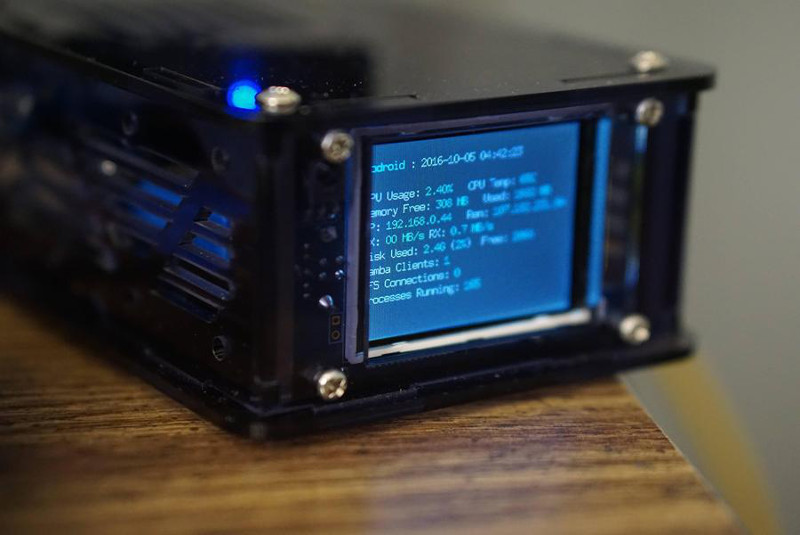
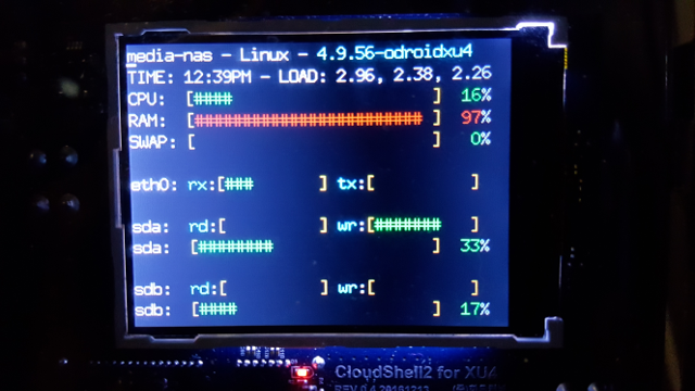 The new LCD status display on the CloudShell


 Stranger Things: The Game has a color palette that is reminiscent of a classic SNES box
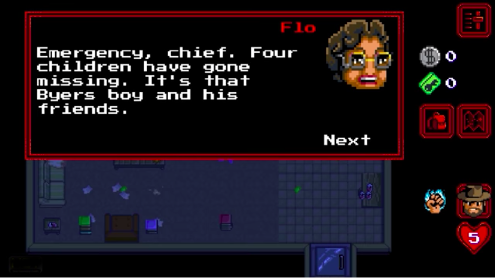 The game follows a freestyle approach from the series
 The later chapters are no picnic, but if I can make it through, you can too
 Have you ever seen such a glorious moustache? No? Then fight him Morty!
 The game is so well designed that you will swear that you have seen the characters sporting those outfits in the show
 The funnest part of this game, if you snap out of it, is seeing you are handling a gadget within a gadget, which is super meta
 Playing with multiple characters was the best thing in the 1990s
 This start screen song and splash screen is etched on every 1990s gamer mind
 Nothing was more satisfying than hitting the boss with the backup bazooka


 Figure 1 - Andrea enjoys spending time with her two daughters
 Figure 2 - Artwork by Andrea called A Tragically Hip Mountain Goat"
  Figure 3 - Artwork by Andrea called Victoria Harbour Town Dock"