

This is the continuation of the initial January 2020 magazine article titled “Android Things”, which details using a new Google-backed operating system which facilitates using the GPIO pins on ODROID devices.
I2C
You can also use I2C on the ODROID board with Android things. You can use any I2C API provided by the Android things. The Android Things supports various sizes of data transmission, byte, word and buffered data.
I ported the Weather board 2 (https://www.hardkernel.com/product-category/sensor/) example to Android with Android things. Also I ported I2C display (https://www.hardkernel.com/product-category/display/). Like other familiar I2C devices, both of the above devices are connected with 4 wires, Voltage, Ground, I2C SDA and I2C SCL. In the examples, I connected I2C wires to the I2C-2.
Most of pre-procedure are same to GPIO procedure. Add permission to the manifest, import and call the instance of PeripheralManager to the project source code. However, you do not need to get a GPIO instance. You need to call the openI2cDevice method to get the I2C device instance.
...
List i2cBusList = manager.getI2cBusList();

I2cDevice device  = manager.openI2cDevice(i2cBusList.get(0),
                      I2C_DEVICE_ADDRESS);
// or i2cDevice device = manager.openI2cDevice(“I2C-2”,
//                         I2C Device Address);
...
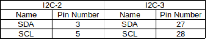
The I2C Interface names are I2C-2 and I2C-3. Each I2C interface consists of pins 3,5 and pins 27, 28. When you get the I2C bus device, you should set the I2C device address for each I2C chip. In this case, a weather board2 consists of two I2C chips. So, I created two I2C device instances. One instance is linked by 0x76 to the BME280. The chip offers temperature, pressure and humidity values. And the other instance is linked by 0x60 to the SI1132. The chip offers UV, Visible and IR values. And I2C LCD has one I2C chip, so I created one I2C instance. It linked by 0x27 for control the LCD. Like this, you should create I2C device instance for each device with their own address.
Through the I2C instance, you can communicate with the device. Android things provide many methods. For reading the data from a device, it provide read, readRegBuffer, readRegByte and readRegWord method. Also for writing data to device, it provides write, writeRegBuffer, writeRegByte and writeRegWord. The Android Things official website provides a lot of information.
I2C Device method reference - https://bit.ly/36yY6N0.
By using the I2C API, I built a wrapper class for weather board2 and I2C LCD. Here is a part of the example code to read and write data with the Android things API.
…
private void softrst() throws IOException {
    device.writeRegByte(reg.RST, POWER_MODE.SOFT_RESET_CODE);
}

private byte getPowerMode() throws IOException {
    return (byte) (device.readRegByte(reg.CTRL_MEAS) & 0b11);
}
...
The code is part of BME280.java. First method is called to soft reset the chip and second method is called to get chip’s power mode. Each API’s first parameter is the address of the register in the chip. On the write method, second parameter is usually the data to transfer. also on the read method, second parameter is usually not exist. However, if you want to read data by buffer, you need buffer to read and the buffer is passed as a second parameter.
You can test or use the project. Here is the link.
Weather board2 with android things example - https://bit.ly/3aKqjnr. I2C LCD with android things example - https://bit.ly/2RUvIzJ.
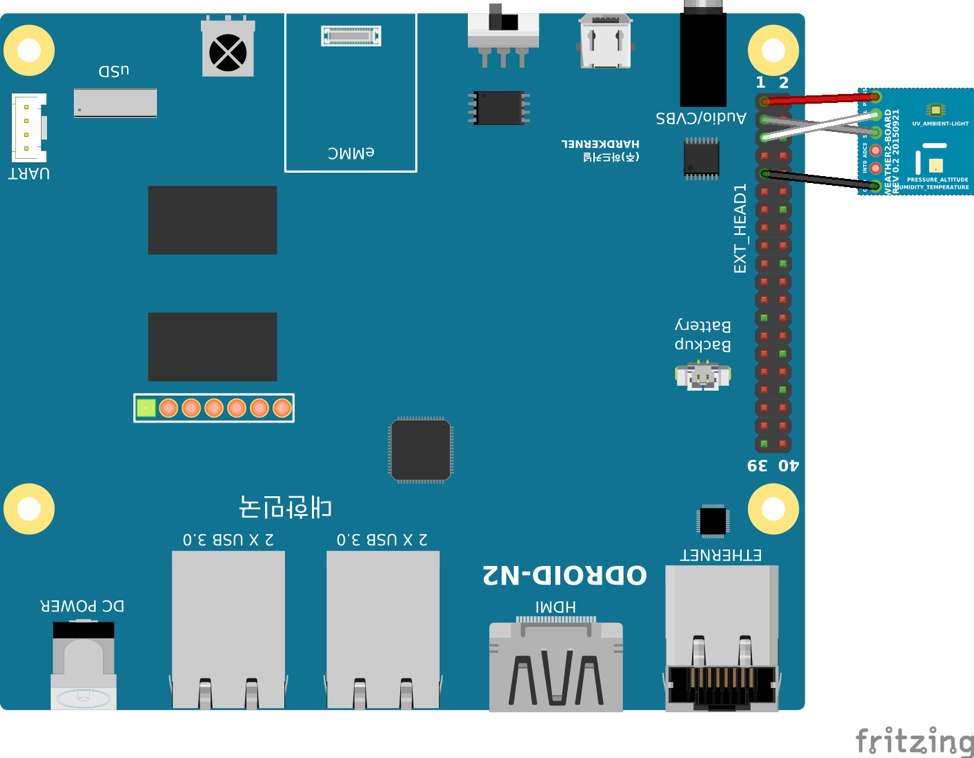
Following is the Weather board 2 Hardware connection:
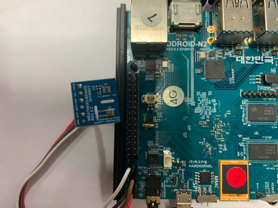
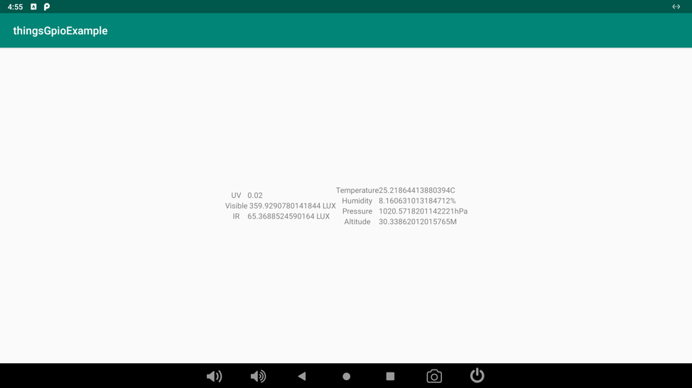
The Weather board 2 Output Result would be like so:
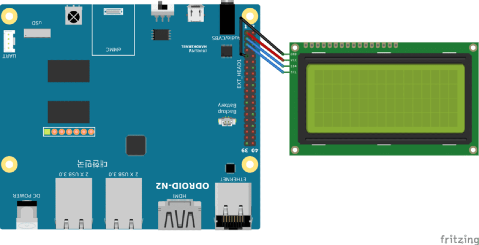
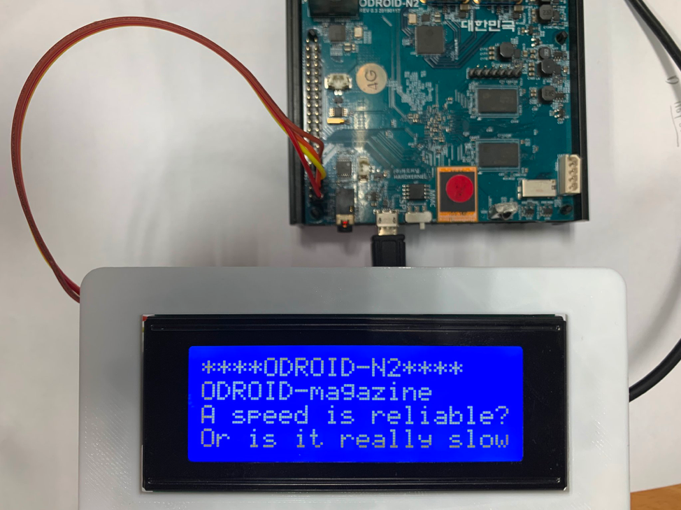
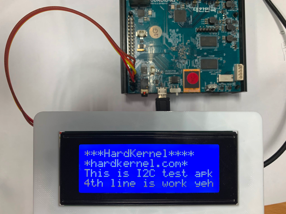
Following is the I2C LCD hardware connection and result:
PWM
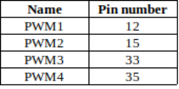
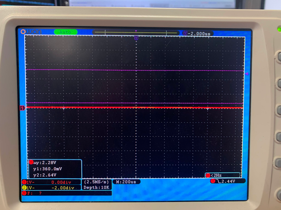
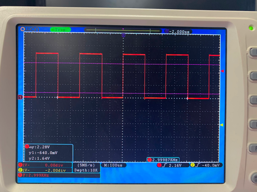
The android Things also support the PWM. There are many methods to configure and control the PWM interface. You can set the PWM Frequency via setPwmFrequency. Before enabling the pin, you must set frequency via this method. Also you can set PWM duty cycle by setPwmDutyCycle between 0 and 100. Frequency and duty cycle settings can be set in both enabled and disabled state and will be remembered.
Please check the Reference. https://developer.android.com/things/sdk/pio/pwm.
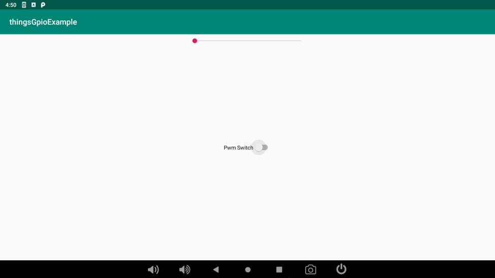
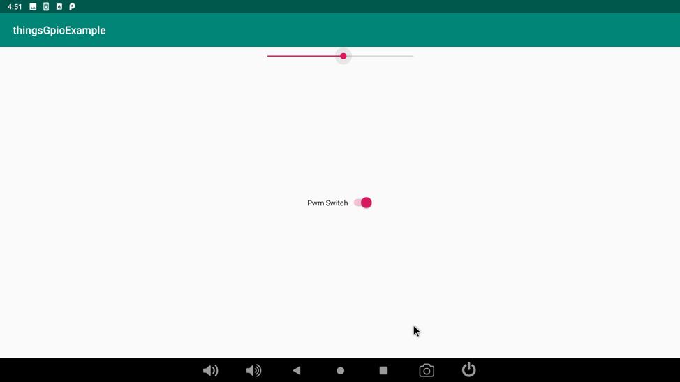
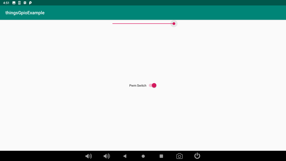
Here is the PWM testing project. In this example, you can turn on and off a PWM pin. and change duty cycle via progress bar on the Application: https://github.com/xiane/thingsGpioExample/tree/pwm.
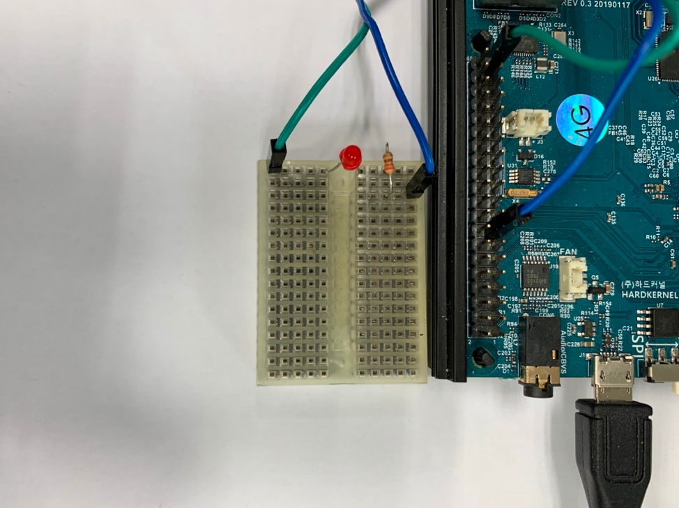

Note that the voltage at GPIO pins on ODROID-N2 are all 3.3V.
Reference https://bit.ly/36qpFrW
Be the first to comment