

The ODROID-MC1 has become an interesting cluster system for experimenting, e.g., with Docker swarm implementations [1] and cryptocurrency mining [2-4]. A brief introduction to the ODROID-MC1 has been given in [5]. A single ODROID-MC1 consists of four slimmed-down ODROID-XU4 nodes, each equipped with a Samsung Exynos 5 Octa (5422). The Exynos 5 Octa is a two-socket ARM Big.LITTLE system consisting of quad-core Cortex-A15 and Cortex-A7 CPUs, clocked at 2GHz and 1.4GHz respectively. The CPUs feature heterogeneous multi-processing (HMP). Each node is equipped with 2GB of LPDDR3 RAM and with a Mali-T628 MP6 GPU, which supports OpenGL ES 3.1/2.0/1.1 and the full OpenCL 1.2 profile. Furthermore, the boards feature gigabit ethernet and is actively fan cooled.
In [6] a general introduction to cluster computing using several ODROID-XU4s is given and the concept of MapReduce topologies is briefly described. The discussion in [7] presents some first parallel examples of the computation of a Mandelbrot set with the MPJ Express message passing library that is implemented in JAVA. When it comes, to scientific computing, JAVA is not the optimal choice due to its performance limitations. In physics and engineering applications, C++, C, or FORTRAN are still the dominating languages for writing scientific code [8].
Common state-of-the-art simulations employ hundreds of thousands CPU cores on high-performance computing (HPC) systems [8,9] to solve big societal challenges. In this context, the scalability and the simulation kernel performance are key to efficient multi-core computations, i.e., it is not only essential to have highly optimized code at hand that runs efficiently on a single core, but also to allow for increasing computational efficiency under an increase of the number of computational cores. While the single core performance is in general enhanced by compute kernel tuning techniques such as loop vectorization, cache line miss avoidance, and intelligent programming, the parallel efficiency can be measured by means of strong scaling experiments. In such experiments the number of cores is continuously doubled for a given problem size. Ideally, the time-to-solution is bisected with every doubling. In such parallel computations, each of the processes solves a subset of the original problem. With an increasing number of cores, the network communication overhead increases as well, which leads to a decrease of efficiency. The best-scaling simulation codes are, able to scale up from a small number of cores to hundreds of thousands of processes [8-10].
The ODROID-MC1 can be seen as a small HPC system and is also well suited for the simulation of small to medium-scale scientific problems. Especially its low power consumption and its low price make it ideal for parallel code development and for procurement in smaller departments or companies, or at universities for educational purposes.
The following text will be described how to setup a cluster system with a shared file system using the Network File System (NFS) and the Message Passing Interface (MPI) together with the cluster job scheduler SLURM. Examples on how to run parallel computations on this system are given. An example from Computational Fluid Dynamics (CFD) corroborates the applicability of the ODROID-MC1 to solve scientific problems. The presented steps are the technical details that are behind the simulations and analyses discussed in [10].
Setting up the cluster system
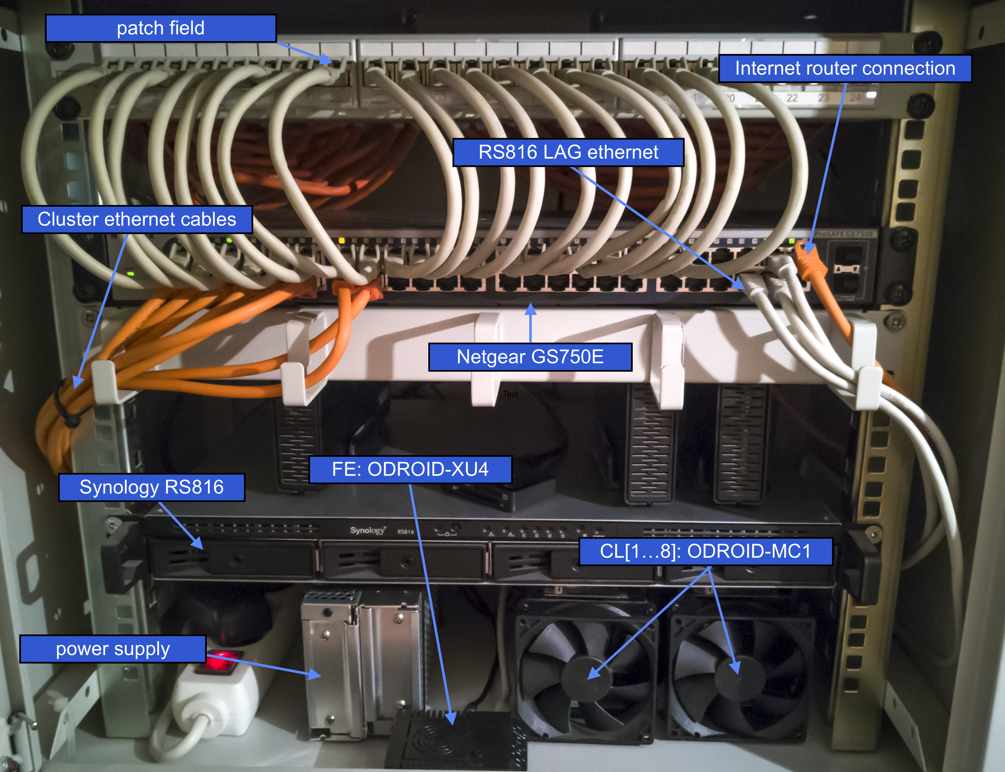
The cluster system consists of a front end node, which is a single ODROID-XU4 equipped with a 16GB eMMC 5.0 module, the ODROID-MC1, a Synology 4-bay Rackstation RS816, a GS750E ProSAFE Web Managed 50-port Gigabit Ethernet Switch, and an internet gateway. Figure 1 shows a photo of the current setup mounted in a 19" rack.
The RS816 serves as a DHCP and NFS server and is connected to the switch with a dual port link aggregation configuration. The switch connects the different components. Obviously, the RS816 and the GS750E can be replaced by any other server and switch with the same functionality, e.g., the front end node itself can serve as a DHCP and NFS server. For the following explanation it is assumed that access to the internet is granted via the gateway with the local IP 192.168.1.1, the server is named ‘FS’, is up and running, and has an IP address of 192.168.1.2. In the present example, the server exports the three directories via NFS:
- /homes/ (will hold user home directories)
- /netopt/ (will contain shared software)
- /work/ (will be used as work space for computations)
The front end node will be identified by the name ‘FE’ and will be assigned the IP 192.168.1.100. The cluster nodes will be named CL[1...4] and will have the IP addresses 192.168.1.101 through 192.168.1.104. First, the configuration of the front-end node is presented before general software installation and the cluster node installation are discussed.
Front end node installation
First, the Ubuntu Linux image needs to be installed on the eMMC module of the ODROID-XU4 front end node or on an SD-card. A great step-by-step explanation can be found online under [11]. For the cluster nodes it is sufficient to install the minimal Ubuntu image. Note that the cluster installation has been tested for Ubuntu Linux 16.04 Xenial. Some details on installing the cluster system on Ubuntu Linux 18.04 Bionic can be found in Sec. 5. To install the front end, the following tasks need to be performed as superuser. The first thing to do after login is set a new password and generate a key for easy login
$ passwd
$ ssh-keygen -t rsa
This will install the ssh-key for root in /root/.ssh/id_rsa. This key will in a later stage be copied to the cluster nodes to allow for easy administration.
IP address and hostname setup
On the system FE, a fixed IP 192.168.1.100 is assigned via updating the file /etc/network/interfaces to contain
auto lo
iface lo inet loopback

auto eth0
iface eth0 inet static address 192.168.1.100
gateway 192.168.1.1
netmask 255.255.255.0
dns-nameservers 192.168.1.1
The name of the system can be updated by adding
FE 192.168.1.100to /etc/hosts and by replacing odroid in /etc/hostname by FE. To furthermore make the system aware of the cluster nodes, i.e., if your DHCP server does not assign the correct names to the nodes, add them, FS, and FE to /etc/hosts as well
CL1  192.168.1.101
CL2  192.168.1.102
CL3  192.168.1.103
CL4  192.168.1.104
FS  192.168.1.2
A restart of the system makes sense at this stage of configuration.
Installation and configuration of the automounter
To automatically mount the shares of the NFS server, the automounter is installed via:
$ apt-get update
$ apt-get upgrade
$ apt-get install autofs
Then, modify the file /etc/auto/master and add the following to the end of the file:
/nfs_mounts /etc/auto.nfsSubsequently, create the file /etc/auto.nfs with the following content:
netopt -fstype=nfs,rw,soft,tcp,nolock,uid=user FS:/volume1/shares/netopt
homes -fstype=nfs,rw,soft,tcp,nolock,uid=user FS:/volume1/shares/homes
work -fstype=nfs,rw,soft,tcp,nolock,uid=user FS:/volume1/shares/work
This mounts NFS exports from the NFS server with the username user located at /volume1/shares on the server. Note that the username user must exist on both systems FS and the FE. Furthermore, create the corresponding directories:
$ mkdir /nfs_mounts
$ mkdir /netopt
$ cd /netopt
$ ln -s /nfs_mounts/netopt
$ cd /home
$ ln -s /nfs_mounts/homes/user
$ cd /home/user
$ ln -s /nfs_mounts/work
Note that the folders /nfs_mounts/netopt, /nfs_mounts/homes, and /nfs_mounts/work do not exist at this stage, will, however, become available upon starting the automounter. Therefore, execute
$ service autofs restartIt also makes sense for both the user and root to add the paths of the software that will be installed in the subsequent section to the path search directory environment variables. Therefore, add to the file ~/.profile
$ export PATH=$PATH:/netopt/mpich/bin
$ export PATH=/netopt/slurm/bin:$PATH
$ export PATH=/netopt/munge/bin:$PATH
Software installation for parallel cluster computation
All shared software will be installed on the shared NFS resource /netopt. All sources will be downloaded and configured in the subdirectory /netopt/install. The following is performed on the front end FE and assumes that a compiler suite such as llvm or the GNU compiler suite is available.
Installation of MPICH
To allow for parallel software development, a parallel communication library needs to be installed. In this example the MPICH library version 3.2.1, which is available from www.mpich.org, will be installed with the following commands:
$ cd /netopt/install
$ mkdir mpich
$ cd mpich
$ tar -xvf mpich-3.2.1

$ cd mpich-3.2.1
$ ./configure --enable-mpi-cxx --prefix=/netopt/mpich-3.2.1
$ make -j 4
$ make install

$ cd /netopt
$ ln -s mpich-3.2.1 mpich
Installation and configuration of MUNGE
For the installation of the job scheduler SLURM, the MUNGE services (here MUNGE 0.5.13; available from https://dun.github.io/munge/) need to be installed. MUNGE is an authentication service for creating and validating credentials that is necessary for authenticated scheduling. To install MUNGE first do
$ apt-get install mungeThis allows to have all necessary start scripts and run service scripts at hand. To install, however, the latest version of MUNGE, the aforementioned source code is downloaded and stored in /netopt/install. To compile MUNGE and install it run
$ cd /netopt/install
$ mkdir munge
$ cd munge
$ tar -xvf munge-0.5.13.tar.gz

$ cd munge-munge-0.5.13   .
$ /configure --prefix=/netopt/munge-0.5.13
$ make -j 4
$ make install

$ cd /netopt
$ ln -s munge-0.5.13 munge

$ cd munge
$ mv etc etc.old
$ mv var var.old
$ ln -s /etc
$ ln -s /var
Note that the logs of MUNGE will this way be written to the local file system /var and the configuration is performed in /etc. To configure MUNGE, a secret MUNGE key needs to be generated by:
$ dd if=/dev/random bs=1 count=1024 > /etc/munge/munge.keyNote that in a later stage (see Sec. 2.3.2) the file /etc/munge/munge.key is copied to the cluster nodes. Furthermore, since the compiled MUNGE installation replaces the previously installed version, the link to the MUNGE executable needs to be updated:
$ cd /usr/sbin
$ mv munged munged.old
$ ln -s /netopt/munge/sbin/munged
Installation of PMIX
Another tool that needs to be installed is PMIX (here PMIX 2.1.0; available from https://github.com/pmix/pmix/releases):
$ cd /netopt/install
$ mkdir pmix
$ cd pmix
$ tar -xvf pmix-2.1.0.tar.gz

$ cd pmix-2.1.0
$ ./configure --prefix=/netopt/pmix-2.1.0
$ make -j 4
$ make install

$ cd /netopt
$ ln -s pmix-2.1.0 pmix
Installation and configuration of SLURM
Finally the scheduler SLURM (here SLURM 17.11.3-2; available from https://slurm.schedmd.com) is installed. Similar to MUNGE, first the Ubuntu SLURM is installed via
$ apt-get slurm-llnl libslurm-devThen, the latest version is installed in /netopt via
$ cd /netopt/install
$ mkdir slurm
$ cd slurm
$ tar -xvf slurm-17.11.3-2.tar.gz

$ cd slurm-17.11.3-2
$ ./configure --prefix=/netopt/slurm-17.11.3-2 --sysconfdir=/etc/slurm-llnl --with-munge=/netopt/munge \
                --with-pmix=/netopt/pmix
$ make -j 4
$ make install

$ cd /netopt
$ ln -s slurm-17.11.3-2 slurm
To configure SLURM, the file /etc/slurm-llnl/slurm.conf is modified to contain
# GENERAL
ControlMachine=FE
AuthType=auth/munge
CryptoType=crypto/munge
MpiDefault=none
ProctrackType=proctrack/pgid
ReturnToService=1
SlurmctldPidFile=/var/run/slurm-llnl/slurmctld.pid
SlurmdPidFile=/var/run/slurm-llnl/slurmd.pid
SlurmdSpoolDir=/var/spool/slurmd
SlurmUser=slurm
StateSaveLocation=/var/spool/slurmctld
SwitchType=switch/none
TaskPlugin=task/affinity
TaskPluginParam=sched

# SCHEDULING
FastSchedule=1
SchedulerType=sched/backfill
SelectType=select/cons_res
SelectTypeParameters=CR_Core

# LOGGING AND ACCOUNTING
AccountingStorageType=accounting_storage/none
ClusterName=odroid
JobAcctGatherType=jobacct_gather/none
SlurmctldDebug=verbose
SlurmctldLogFile=/var/log/slurmctld.log
SlurmdDebug=verbose
SlurmdLogFile=/var/log/slurmd.log

# COMPUTE NODES
NodeName=CL[1-4] CPUs=8 RealMemory=1994 State=UNKNOWN
PartitionName=batch Nodes=CL[1-4] OverSubscribe=EXCLUSIVE Default=YES MaxTime=INFINITE State=UP
In /usr/sbin, update the following links:
$ cd /usr/sbin
$ mv slurmctld slurmctld.old
$ mv slurmd slurmd.old
$ mv slurmstepd slurmstepd.old

$ ln -s /netopt/slurm/sbin/slurmctld
$ ln -s /netopt/slurm/sbin/slurmd
$ ln -s /netopt/slurm/sbin/slurmstepd
Also make sure that you add the following folder and change the permissions as follows
$ mkdir /var/spool/slurmctld
$ chown slurm:slurm /var/spool/slurmctld
Cluster node installation
The cluster nodes also use the Ubuntu Linux minimal image. The following is exemplarily shown for the first cluster node CL1 with IP 192.168.1.101 and needs to be applied to all cluster nodes.
General cluster node configuration
After installation of the SD-card make sure that the system is up-to-date:
$ apt-get update
$ apt-get upgrade
$ apt-get dist-upgrade
Also be sure to copy the folder /root/.ssh from FE to CL1, i.e., on FE execute the following ((make sure that rsync is installed):
$ rsync -av /root/.ssh CL1:/root/Then, follow the steps in Sec. 2.1.1 and Sec. 2.1.2 to have the correct IP address (192.168.1.101), hostname (CL1), and the automounter running.
Integration into the cluster system
Install all necessary packages on CL1:
$ apt-get install munge slurm-llnl libslurm-devThen, the MUNGE key generated in Sec. 2.2.2 and residing in /etc/munge/munge.key on FE and the SLURM configuration file found in /etc/slurm-llnl/slurm.conf need to be transferred to CL1 by running
$ rsync -av /etc/munge/munge.key CL1:/etc/munge/
$ rsync -av /etc/slurm-llnl/slurm.conf CL1:/etc/slurm-llnl/
on FE. At this stage it makes sense to restart the cluster node. After installing each node, the system is almost ready for cluster computation.
Cluster administration
To have the scheduler running, the following commands need to be executed on the nodes
$ sudo service munge start
$ sudo service slurmd start
and on FE:
$ sudo service munge start
$ sudo service slurmctld start
The node status can be checked by:
$ scontrol show nodesor by:
$ sinfo -N --longIf one of the nodes is in state DOWN or UNKNOWN it can be resumed by
$ scontrol update NodeName=NAME State=RESUMEwhere NAME is the name of a node, e.g., CL1.
Job submission
Now that the cluster is fully functional, jobs can submitted to the scheduler, which need a job file such as:
#!/bin/bash -x
#SBATCH --nodes=4           // allocates 4 nodes for the job
#SBATCH --ntasks-per-node=2       // starts 2 MPI ranks per node
#SBATCH --cpus-per-task=4       // for each MPI rank per node 4 OpenMP threads are reserved
#SBATCH --output=mpi-out.%j       // location of the output file
#SBATCH --error=mpi-err.%j       // location of the error file
#SBATCH --time=00:20:00       // wall time of the job
#SBATCH --partition=batch        // the name of the partition

export OMP_NUM_THREADS=${SLURM_CPUS_PER_TASK}        // information for OpenMP

srun --mpi=pmi2 COMMAND      // runs the command COMMAND in parallel
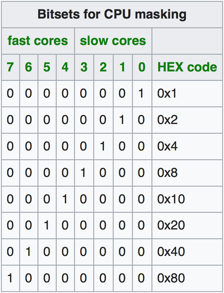
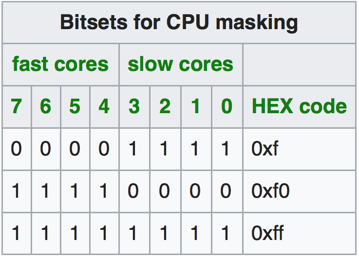
Jobs can be scheduled to the nodes differently, i.e., either individual cores, the Cortex-A7 (slow) or Cortex-A15 (fast) cores, or both can be used for computation. This is configured by the srun command in the job script:
srun --cpu-bind=verbose,mask_cpu:ABxCD --mpi=pmi2 COMMAND // uses mask ABxCD for schedulingThe mask_cpu option allows to specify the mask for execution. The masks for using a whole single Cortex system or both are show in Tables 1 and 2.
Example: Flow simulation on the ODROID-MC1
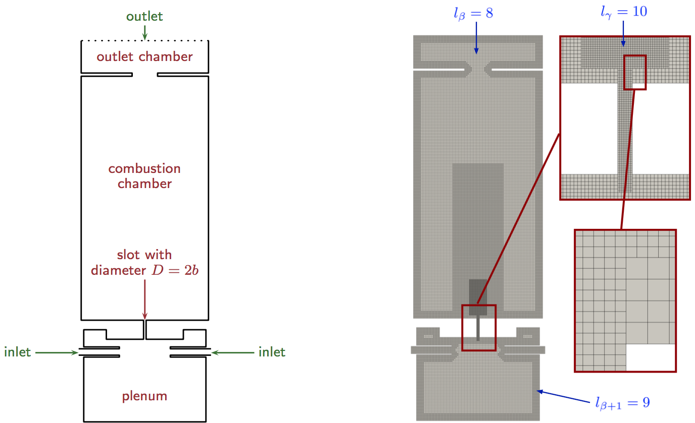
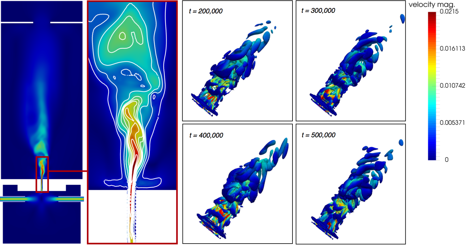
To show that the ODROID-MC1 system can be used for scientific simulations, an example of the simulation of the flow in a slot burner geometry [10], see Fig. 2; left side, is presented in the following. The simulation uses a lattice-Boltzmann code [12], which solves the governing equations of fluid mechanics on a space-discretizing Cartesian mesh, i.e., the Boltzmann equation is solved for all spatial location within this mesh in time.
At each time step, at each location in the mesh, a velocity vector and the density is computed by a two-stage algorithm that locally simulates the collision of particles in a finite volume and transports collision information to neighboring locations. The mesh is generated by a parallel mesh generator [13] and is shown in Fig. 2 on the right side. Especially in the vicinity of the walls and in the burning jet region, the mesh is locally refined to have a sufficient resolution to capture the main flow features. Figure 3 shows the results of the computation, which is produced using only the fast Cortex-A15 cores of the ODROID-MC1. The simulation is run for 24 hours. Obviously, a jet develops in the slot region that reaches into the combustion chamber. On the left a cross-section in the slot region is shown with contours of the velocity magnitude. The right side shows three-dimensional contours of the vortical structures generated at different time steps of the simulation. As mentioned in the introduction, scalability is an important aspect in HPC simulations. Therefore, strong scalability measurements are performed for the whole system.
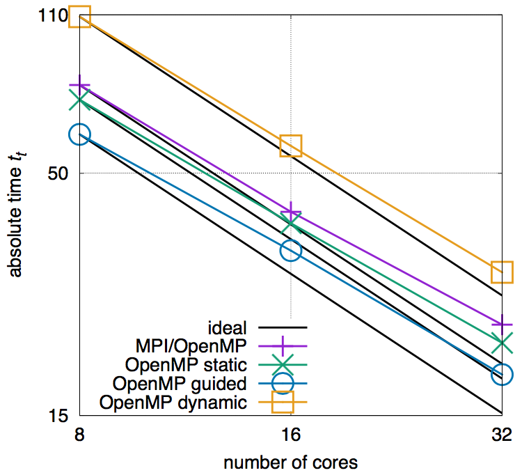
Figure 4 shows the scalability of the simulation using different parallelization strategies, i.e., using a pure MPI and hybrid MP/OpenMP parallelization strategies, latter with different OpenMP scheduling options for parallelized loops. The black lines represent the ideal scaling behavior. In Figure 4 it can be seen that among all cases, the hybrid MPI/OpenMP using the guided loop parallelization strategies performs best and is hence the method of choice for a simulation. The effect of the communication overhead is already visible from the discrepancy to the ideal black line. This configuration does, however, not outrun the performance of using only the fast Cortex-A15 cores (as used for the slot burner simulation). For more details, the interested reader is referred to [10] from where the results are taken and which furthermore discusses the energy consumption of the ODROID-MC1 and compares its performance to state-of-the-art German HPC systems.
Summary and conclusion
The ODROID-MC1 is a promising system for cluster operation and for the simulation of small to medium scientific problems. The corresponding software installation is straightforward. The present article has given a step-by-step manual on how to setup the cluster system for parallel computation using MPI with MPICH and PMIX. The scheduler SLURM uses MUNGE for authentication and allows job pinning for pure MPI and hybrid MPI/OpenMP job executions. An example of the simulation of the flow in a slot burner configuration shows the ODROID-MC1 to be a suitable system for the simulation of such problems. The scalability of the simulation software on the system is quite sufficient to compute solutions in a human-manageable time. That is, the ODROID-MC1 is for small departments or research groups a cost-effective alternative to x86-based HPC systems if large-scale simulations are not the main target.
Further remarks
Instead of installing each cluster node individually, it is also possible to install PXE boot and to have each node boot online over the network from TFTP. The root file system is then imported via NFS from a file server. A detailed guide on how to setup PXE boot on ODROID-XU4 can be found on the ODROID Wiki pages [14]. Using the latest Linux Ubuntu 18.04 Bionic, some changes in the installation process are necessary. First of all the network configuration has changed from a setup in /etc/network/interfaces to a configuration via netplan. That is, instead of modifying /etc/network/interfaces, the file /etc/netplan/01-networkd.yaml should be created with the following content (example for CL1)
network:
  ethernets:
      eth0:
         addresses: [192.168.1.101/24]
         gateway4: 192.168.1.1
         nameservers:
           addresses: [192.168.1.1]
         dhcp4: no
  version: 2
Make sure not to use any tabulators in the file for indentation. After that you can run
$ netplan apply
$ netplan --debug apply
which should change your IP right away. Furthermore, the SLURM version in the Ubuntu repository on Bionic is different and you need to install
$ apt-get install slurm-wlminstead of package slurm-llnl. This still delivers you the same directory structure as slurm-llnl and hence there are no further changes necessary.
References
[1] A. Yuen, ODROID-MC1 Docker Swarm: Getting Started Guide, Odroid Magazine (46)(2017)
[2] E. Kisiel, Prospectors, Miners, and 49er’s: Dual GPU-CPU Mining on the ODROID-XU4/MC1/HC1/HC2, Odroid Magazine (51)(2018).
[3] E. Kisiel, Prospectors, Miners, and 49er’s - Part 2: Dual GPU-CPU Mining on the ODROID-XU4/MC1/HC1/HC2, Odroid Magazine (52)(2018).
[4] E. Kisiel, Prospectors, Miners, and 49er’s - Part 3: Operation and Maintenance of Crypto-Currency Mining Systems, Odroid Magazine (53)(2018).
[5] R. Roy, ODROID-HC1 and ODROID-MC1: Affordable High-Performance And Cloud Computing At Home, Odroid Magazine (45)(2017).
[6] M. Kamprath, ODROID-XU4 Cluster, Odroid Magazine (53)(2018).
[7] A. Yuen, ODROID-MC1 Parallel Programming: Getting Started, Odroid Magazine (46)(2017).
[8] D. Brömmel, W. Frings, B. J. N. Wylie, B. Mohr, P. Gibbon, T. Lippert, The High-Q Club: Experience Extreme-scaling Application Codes. Supercomputing Frontiers and Innovations, 5(1), 59–78 (2018). doi:10.14529/jsfi180104
[9] A. Pogorelov, M. Meinke, W. Schröder, Cut-cell method based large-eddy simulation of tip-leakage flow. Physics of Fluids, 27(7), 075106 (2015). doi:10.1063/1.4926515
[10] A.Lintermann, D. Pleiter, W. Schröder, Performance of ODROID-MC1 for scientific flow problems, Future Generation Computer Systems (in press, first online: Jan. 04, 2019). doi:10.1016/j.future.2018.12.059
[11] Odroid Wiki https://wiki.odroid.com/troubleshooting/odroid_flashing_tools
[12] R.K. Freitas, A. Henze, M. Meinke, W. Schröder, Analysis of Lattice-Boltzmann methods for internal flows. Computers & Fluids, 47(1), 115–121 (2011). doi:10.1016/j.compfluid.2011.02.019
[13] A. Lintermann, S. Schlimpert, J. H. Grimmen, C. Günther, M. Meinke, W. Schröder, W. Massively parallel grid generation on HPC systems, Computer Methods in Applied Mechanics and Engineering 277, 131–153 (2014). doi:10.1016/j.cma.2014.04.009
[14] PXE boot on ODROID-XU4/MC1/HC1, https://wiki.odroid.com/odroid-xu4/application_note/software/pxe_boot
Be the first to comment