
For those designing with an SBC or micro-controllers, having a model can be important. I want to share a simple, lightweight and dynamic framework for the generation of SBC and microcontroller models written in OpenSCAD. When I originally created the OpenSCAD XU4 model a couple years back, https://forum.odroid.com/viewtopic.php?f=97&t=26243, it was a hard coded static model and the only SBC I owned. That worked fine at the time but since then I have acquired a few more SBCs and I have had a need for access to different models while working on various projects.
The current project I'm working on crosses multiple SBCs so I decided to pause and develop the models for the other SBCs involved. Creating models for the whole HK line had been on my project list for awhile but never reached a high enough priority to complete.
Instead of hard-coding all of them I decided that it would be better to create a framework which could handle multiple SBCs and micro-controllers. Using this approach allows access to all of them through a single module call while keeping the code small and efficient. This is important to me since large complex assemblies can take a considerable amount of time to compile in OpenSCAD. For comparison I recently examined a similar STEP and DXF model of the HK Odroid H2. The STEP model was 993KB and the DXF file size was 1,273KB. It may not be particularly large for a 3D static model but when several models are involved it can start to become significant. In contrast, all of the code and the SBC data set used in this framework, which represents 8+ SBCs, totals 83KB and the efficiency of this method will only increase as more models are added.
For me, the most important criteria for most of my work is the physical dimensions so that locating and checking can be done quickly and easily as I develop designs. To keep things as accurate as possible, the information for the models was derived from both HK supplied 2D mechanical layout drawings and actual measurements of the SBCs I own. In the cases were I did not own a particular SBC, I also used component data sheets from the manufacturer. When the component manufacturer was not known, I examined data-sheets from multiple manufacturers to generalize a component design.
Aesthetics are not as important to my use as either code size or render speed, so it is secondary in this model framework. With that said, I have spent time developing better component models so they are more complete and do look better then the original XU4 model components. I will be maintaining and adding to this SBC library as needed or as other HK SBC's become available.
The SBC's currently supported and complete are: Hardkernel's ODROID-C1+, ODROID-C2, ODROID-XU4, ODROID-N1, ODROID-N2, ODROID-MC1, ODROID-HC1, ODROID-HC2 and ODROID-H2.
Sometimes only board dimensions and hole layout is needed for a particular design and they can be added quickly and easily in this framework by editing an ASCII configuration file. I did this for testing and to illustrate the technique for the following SBCs:
Raspberry Pi Foundation's Model 3B+, 3B, 3A+, 2, 1A+, Pine64's A64, Rock64, RockPro64.
Using the Framework
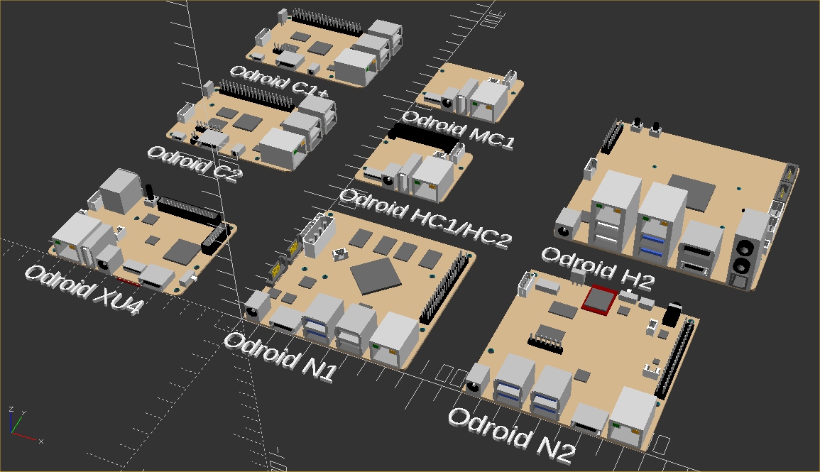
Any of the models can be called by passing the requested SBC model in the form of sbc("xu4"). Below is example code that was used to generate the opening picture.
Test.scad
include

translate ([-120,0,0]) sbc("xu4");
linear_extrude(height = 2) {translate([-120,-20,0]) text("Odroid XU4");}
translate ([-120,110,0]) sbc("c2");
linear_extrude(height = 2) {translate([-120,90,0]) text("Odroid C2");}
translate ([-120,200,0]) sbc("c1+");
linear_extrude(height = 2) {translate([-120,180,0]) text("Odroid C1+");}
translate ([0,0,0]) sbc("n1");
linear_extrude(height = 2) {translate([0,-20,0]) text("Odroid N1");}
translate ([0,120,0]) sbc("hc1");
linear_extrude(height = 2) {translate([0,100,0]) text("Odroid HC1/HC2");}
translate ([0,200,0]) sbc("mc1");
linear_extrude(height = 2) {translate([0,180,0]) text("Odroid MC1");}
translate ([120,120,0]) sbc("h2");
linear_extrude(height = 2) {translate([120,100,0]) text("Odroid H2");}
translate ([120,0,0]) sbc("n2");
linear_extrude(height = 2) {translate([120,-20,0]) text("Odroid N2");}
A component of an SBC that is not needed or needs to be disabled temporarily, can be excluded by adding a minus sign to its class entry in the sbc_models.cfg file. One example of this use might be for eMMC's. Both the eMMC and the plug(attached to the PCB) are available. Below is an illustration for the XU4 to disable the display of the eMMC while displaying the eMMC plug.
// Hard Kernel ODROIDs
["xu4",83,59,1,3.5,17,6, // sbc model, pcb size and component height
3.5,3.5,3,3.5,55.5,3, // pcb holes 1 and 2 location and pcb hole size
79.5,3.5,3,79.5,55.5,3, // pcb holes 3 and 4 location and pcb hole size
79.61,22,3,28.39,42,3, // pcb holes 5 and 6 location and pcb hole size
0,0,3.3,0,0,3.3, // pcb holes 7 and 8 location and pcb hole size
0,0,0,0,0,0, // pcb holes 9 and 10 location and pcb hole size
14.5,15.75,1.25,59.7,20.55,0,0,"top", // soc1 size, location, roation and side
0,0,0,0,0,0,0,"", // soc2 size, location, roation and side
0,0,0,0,0,0,0,"", // soc3 size, location, roation and side
0,0,0,0,0,0,0,"", // soc4 size, location, roation and side
47.5,13.7,0,"bottom","memory","emmc_plug", // emmc plug location, rotation, side, class and type
45,0,0,"bottom","-memory","emmc", // emmc location, rotation, side, class and type
45.85,5,0,"top","storage","sdcard", // sdcard location, rotation, side, class and type
79,7.15,0,"top","switch","slide_4x9", // switch location, rotation, side, class and type
25.925,52.925,0,"top","button","momentary_6x6x9", // pwrbutton location, rotation, side, class and type
34.85,-1,0,"top","plug","pwr5.5_7.5x11.5", // pwrplug location, rotation, side, class and type
26,0,0,"top","usb2","single_vert_a", // usb2 location, rotation, side, class and type
7.55,41.6,180,"top","usb3","double_stacked_a", // usb3 location, rotation, side, class and type
7.4,0,0,"top","network","rj45_single", // ethernet location, rotation, side, class and type
60,-1,0,"top","video","hdmi_a", // hdmi location, rotation, side, class and type
0,37.8,90,"top","plug","uart_micro", // uart location, rotation, side, class and type
0,25,270,"top","plug","rtc_micro", // rtc location, rotation, side, class and type
27,22,90,"top","fan","micro", // fan location, rotation, side, class and type
35.4,52.25,0,"top","gpio","encl_header_30", // gpio1 location, rotation, side, class and type
76.25,32.5,270,"top","gpio","encl_header_12", // gpio2 location, rotation, side, class and type
43.8,27.25,0,"top","ic","ic_5.75x5.75", // pmic location, rotation, side, class and type
32.5,40.5,0,"top","ic","ic_7x7", // usbhum 7mm location, rotation, side, class and type
11.7,22.8,0,"top","ic","ic_6x6", // nic location, rotation, side, class and type
0,0,0,"*","*","*"], // end
Modifying and Adding Components
The framework is setup so that both SBCs and components can be easily added or modified and the resulting models can be used regardless of the state of completion. The framework consists of three parts, the SBC data set (sbc_models.cfg), the main module(sbc_models.scad) and a library of components(sbc_library.scad).
sbc_models.cfg is an ASCII file that can be modified with any text editor. It contains a data set for the description of a given SBC. The schema is as follows:
"model",pcbsize_x, pcbsize_y, pcbsize_z, pcbcorner_radius, topmax_component_z, bottommax_component_z
pcb_hole1_x, pcb_hole1_y, pcb1_hole_size, pcb_hole2_x, pcb_hole2_y, pcb2_hole_size
pcb_hole3_x, pcb_hole3_y, pcb3_hole_size, pcb_hole4_x, pcb_hole4_y, pcb4_hole_size
pcb_hole5_x, pcb_hole5_y, pcb5_hole_size, pcb_hole6_x, pcb_hole6_y, pcb6_hole_size
pcb_hole7_x, pcb_hole7_y, pcb7_hole_size, pcb_hole8_x, pcb_hole8_y, pcb8_hole_size
pcb_hole9_x, pcb_hole9_y, pcb9_hole_size, pcb_hole10_x, pcb_hole10_y, pcb10_hole_size
soc1size_x, soc1size_y, soc1size_z, soc1loc_x, soc1loc_y, soc1loc_z, soc1_rotation, "soc1_side",
soc2size_x, soc2size_y, soc2size_z, soc2loc_x, soc2loc_y, soc2loc_z, soc2_rotation, "soc2_side",
soc3size_x, soc3size_y, soc3size_z, soc3loc_x, soc3loc_y, soc3loc_z, soc3_rotation, "soc3_side",
soc4size_x, soc4size_y, soc4size_z, soc4loc_x, soc4loc_y, soc4loc_z, soc4_rotation, "soc4_side",
component_x, component_y, component_rotation, "component_side", "component_class","component_type"
Part of the schema has a fixed length and includes the SBC model, PCB xyz size, corner radius, top and bottom maximum component heights, up to 10 thru holes and up to 4 SOCs. This part of the schema is the same length for all SBC definitions. The number of component entries is unlimited in quantity and I'll discuss that in a minute. I believe the basic PCB data is self explanatory. The physical dimensions(xyz) must be known in order to create a PCB. The top and bottom maximum component Z height can be useful for designs using this library. PCB holes are limited to 10 defined by their xy center location and diameter. The number can be easily expanded if this becomes restrictive.
I choose to accommodate multiple SOCs and not include them as a component for a couple of reasons. There are already SBCs that are specialized and include multiple processing units. I refer to them all in this framework as SOCs, but they could also be micro-controllers, AI processors, or dedicated communication processors on the PCB, to name a few. By defining them separately from components, additional information such as size and height can be included without burdening every component entry with this additional information. Four entries should be sufficient but it too can be easily expanded in the future without significant modification of the program. SOC entries can be rotated and also be placed on either side of the PCB. If a hole or SOC is not needed, leave scalar values as zero and text entries empty.
The last entry in the schema is for components. A component is anything that is attached to the PCB. Any number of components from the library can be placed per SBC. The algorithm will automatically place as many or as few as defined. There are six values per component. The xy component location for the top of the PCB are measured from the lower left corner of the PCB to the lower left corner of the component or opening, with holes measured to the center. Bottom side components are measured from top left corner of PCB to top left corner of component, when the PCB is rotated around the x axis. All measurements are in mm and as a general rule PCB orientation is with the long side of the PCB along the x axis.
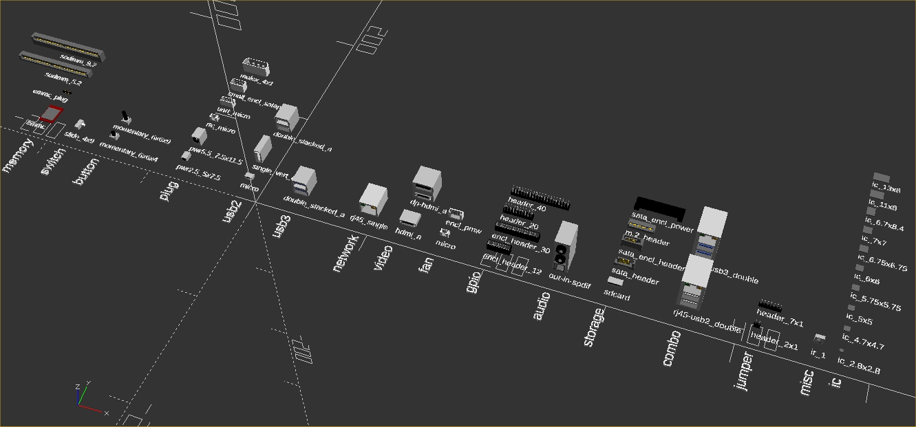
The rotation value does not rotate the component around the xy location. It is a reference to the direction that the component faces and whichever corner of the component is in the lower left after rotation, will assume the xy location specified for the component entry. This allows a uniform means to measure the placement of components regardless of their orientation on the PCB. The schema entry labeled component_side is the side of the PCB the component is to be placed on. So far we covered component_x, component_y, component_rotation and component_side. The last two entries are component_class and component_type. These entries together determine what component is placed. Each component class contains one or more component types. There are currently 17 component classes with corresponding component types:
- memory - emmc, emmc_plug, sodimm_5.2, sodimm_9.2
- switch - slide_4x9
- button - momentary_6x6x9, momentary_6x6x4
- plug - pwr5.5_7.5x11.5, pwr2.5_5x7.5, rtc_micro, uart_micro, molex_4x1, small_encl_satapwr
- usb2 - single_vert_a, double_stacked_a, micro
- usb3 - double_stacked_a
- network - rj45_single
- video - hdmi_a, dp-hdmi_a
- fan - micro, encl_pmw
- gpio - encl_header_30, encl_header_12, header_40, header_20
- ic - ic_2.8x2.8, ic_4.7x4.7, ic_5x5, ic_5.75x5.75, ic_6x6, ic_6.75x6.75, ic_7x7, ic_6.7x8.4, ic_11x8, ic_13x8
- audio - out-in-spdif, jack_3.5
- storage - sata_header, sata_encl_power, sata_encl_header, m.2_header, sdcard
- combo - rj45-usb2_double, rj45-usb3_double
- jumper - header_2x1, header_7x1
- misc - ir_1
Simply put, new SBCs are defined in sbc_model.cfg and new components are added to sbc_library.scad. To add an SBC, modify sbc_models.cfg by creating or copying of an existing SBC entry. Update the relative SBC data and components for the new SBC. When a component type needs to be added, simply add code that draws that component type in the class module the component belongs to, located in sbc_library.scad. There is no checking or validation of any kind so in reality any class can contain any component type. The names are simply the ones I choose to impose some structure that makes sense for my use of the library moving forward.
OpenSCAD has the ability to export models in other formats, so thru export and possible translation, other CAD systems can use these models as well. If you have any questions or problems, or would like to contribute SBC data or components to the library, make a post or send me a PM. I will be maintaining this library and announcing any additional SBC's and components in the forum thread. https://forum.odroid.com/viewtopic.php?f=98&t=33823
For those interested in trying out this SBC model framework, I recommend a more recent build of OpenSCAD that's available at their nightly snapshot repository at http://files.openscad.org/snapshots/.
There is even a recent armhf appimage there that I have verified does work on an XU4 running Ubuntu 18.04. Unfortunately it is not hardware accelerated so it is slow for a design of any significant size. I recently tried to compile the source for the XU4. All dependencies could be met but there was an issue with opengl declaration mismatches. In my brief research, this is common and it looks resolvable using glew or another tool. It is a low priority issue for me now, but I would like to get hardware acceleration working for OpenSCAD on Odroids in the future.
Be the first to comment