

This project’s goal is to use an ODROID to read temperature and humidity data from an SHT15 sensor, as well as explaining how an ODROID communicates with an SHT15 over GPIO pins. SHT15 sensors are manufactured by Sensirion and measure both the temperature and the humidity of their surroundings. Communication with a sensor occurs via an ODROID’s GPIO pins. One GPIO pin connects to the sensor’s SCK pin, which controls how quickly communication occurs. The second GPIO pin connects to the sensor’s DATA pin, which is used to send commands and read results. Once everything has been set up, the ODROID will send a request to measure the temperature or the humidity via the DATA pin, wait for the sensor to complete its measurement, then read the result over the DATA pin.
Connecting the SHT15 sensor
The following diagram outlines how to connect an SHT15 sensor to an ODROID.
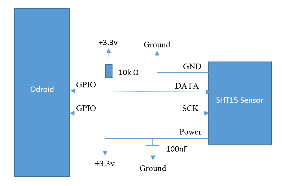
There are two things to note. First, data-sheets are a great place to get information on how to use electronic parts. The circuit in Figure 1 was copied from the sensor’s data-sheet. It’s recommended by the manufacturer as a set-up that yields good measurements. Second, soldering an SHT15 is difficult. To make things easier, this tutorial uses a pre-manufactured SHT15 sensor board.
Required Supplies
To get started, the following parts and tools are needed:
- ODROID (http://bit.ly/1QPVZa9)
- ODROID tinkering kit (http://bit.ly/1LmFcdf)
- SHT15 sensor board (http://bit.ly/1qd22ZL)
- Wires
- Soldering iron and solder
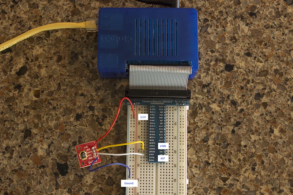
Once you have the SHT15 sensor board, make the following connections after soldering wires to it:
- Connect VCC to the ODROID’s +3.3V power source
- Connect DATA to the ODROID’s GPIO pin #100
- Connect SCK to the ODROID’s GPIO pin #97
- Connect GND to the ODROID’s GND
You should end up with something that looks like Figure 2.
Reading and Writing GPIO values
GPIO pin stands for general-purpose input/output pin. How many of them your ODROID has depends on the model, but in all cases, they’re used to read and write binary data. Binary data is data with only two states, commonly referred to as HIGH and LOW, or 1 and 0. Physically, a HIGH value means the pin voltage is +3.3 volts, and a LOW value means the pin voltage is +0.0 volts. Note that the voltage level depends on the device. For example, an Arduino operates from +5.0 volts to +0.0 volts. If the ODROID is writing data to a GPIO the pin, it will change the voltage between +3.3 volts and +0.0 volts depending on if HIGH or LOW has been written. If the ODROID is reading data, it will measure HIGH when +3.3 volts is applied to the pin, and LOW when +0.0 volts is applied to the pin. For this project, we’re going to read and write data to and from two GPIO pins. At a high level, this involves the following steps:
- Connect your ODROID GPIO pins to the sensor
- Login to Linux on the ODROID and navigate to the GPIO directory
- Initialize a connection with the two connected GPIO pins (one for DATA and one for SCK)
- When needed, set the pins to write mode and write data
- When needed, set the pins to read mode and read data
To get started, login to your ODROID and open up a command line terminal. Some of the following commands need to be executed as root, which can be done with the following command:
$ sudo su -GPIO pins are located in the /sys/class/gpio directory:
$ cd /sys/class/gpioA program called “export” is in this directory, which initializes connections with GPIO pins. A pin needs to be initialized before data can be read from it or written to it. To initialize a connection, pass the identification number of the pin. In this tutorial, we connected the SHT15 sensor’s DATA pin to GPIO pin 100, and the sensor’s SCK pin to GPIO pin 97. These two connections are initialized with the following two commands.
$ echo 100 > /sys/class/gpio/export
$ echo 97 > /sys/class/gpio/export
After these commands complete, you should find the following newly created directories:
/sys/class/gpio/gpio100
/sys/class/gpio/gpio97
These directories contain everything needed to read and write data from their corresponding GPIO pins. The first important file to take note of is “direction.” For GPIO pin 100, it’s found in the file /sys/class/gpio/gpio100/direction. The “direction” file changes a pin between read mode and write mode. You cannot simultaneously read and write data at the same time on a single pin. You can, however, have multiple pins where some are reading data and others are writing data. A pin can be changed to write mode by writing a value of “out” to the “direction” file. Likewise, a pin can be changed to read mode by writing a value of “in” to the “direction” file. For example, the following command changes GPIO pin 100 to write mode:
$ echo out > /sys/class/gpio/gpio100/directionThe next command changes GPIO pin 100 to read mode.
$ echo in > /sys/class/gpio/gpio100/directionTo determine which mode a GPIO pin is in, you can read the “direction” value. For example, the following command determines whether GPIO pin 100 is in read mode or write mode.
$ cat /sys/class/gpio/gpio100/directionThe second important file to take note of is “value”. For GPIO pin 100, it’s found at /sys/class/gpio/gpio100/value. Reading and writing binary data is done using the “value” file. If the pin is in write mode, the “value” file is used to output binary data. If the pin is in read mode, the “value” file is again used, but in this case it reads binary data from the pin. To demonstrate this, we can run a small test to see if the circuit board is connected correctly. When initially connected, the DATA pin should be HIGH and the SCK pin should be LOW. To determine if this is the case, first change both pins to read mode.
$ echo in > /sys/class/gpio/gpio100/direction
$ echo in > /sys/class/gpio/gpio97/direction
Second, read the GPIO value for each pin.
$ cat /sys/class/gpio/gpio100/value
$ cat /sys/class/gpio/gpio97/value
Pin 100 (DATA) should print a value of “1”, and pin 97 (SCK) should print a value of “0”. If this is not the case, possible places to troubleshoot the problem are double-checking your wire connections by using the wire diagram above for reference, and double-checking that the GPIO pins are set to read mode by checking the “direction” file values:
$ cat /sys/class/gpio/gpio100/direction
$ cat /sys/class/gpio/gpio97/direction
Communicating with the SHT15 sensor
At a high level, the following steps result in humidity or temperature data being read from a sensor:
- The ODROID sends a request to the sensor to record either the temperature or the humidity. Note that the sensor cannot read both the temperature and the humidity simultaneously. If both measurements need to be taken, measurements must be done sequentially.
- The sensor begins taking a measurement, and the ODROID waits.
- Once the measurement is completed, the ODROID reads the result from the sensor.
- The ODROID converts the measurement into a human-readable form.
To request that a measurement be taken, the ODROID sends a binary number to the sensor. For example, the number 00000011 requests that the temperature be measured, and the number 00000101 requests that the humidity be measured. The numbers themselves are sent one bit at a time over the DATA pin. The SCK pin controls how quickly values are sent. Take a look at Figure 3, which shows the GPIO pin values when transmitting the number 00000101 (humidity measurement request).
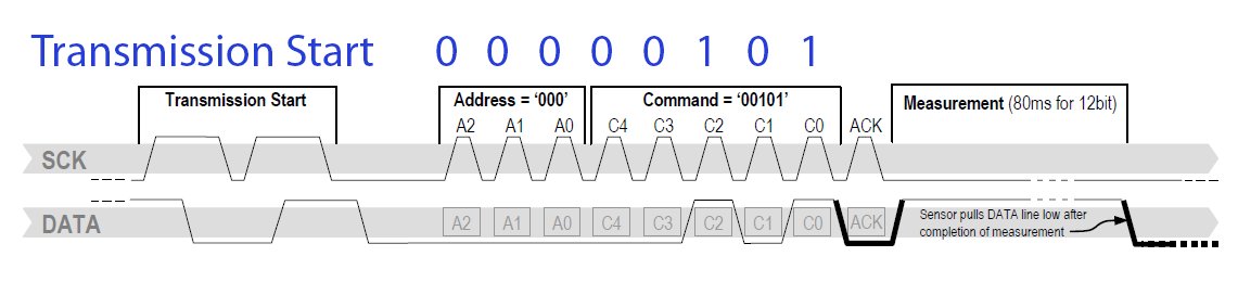
There are three sections of note in Figure 3. The first is the transmission start sequence. This is a combination of HIGH and LOW values transmitted over DATA and SCK that signal the sensor a command is about to be sent. The second section of note is the request number section. In it, the DATA pin transmits each bit 0-0-0-0-0-1-0-1 and the SCK pin varies between 1 and 0. The SCK pin controls the timing of how quickly data is transmitted. When SCK is 0, it indicates that nothing is ready to be read. When SCK is 1, it indicates something is ready to be read. Alternating SCK between 1 and 0 while transmitting each bit over DATA allows the ODROID to send measurement requests to the sensor.
The last section of note in the diagram above is the ACK section, also known as the acknowledgement section. In this section, the ODROID changes the DATA pin to read mode. This causes it to read values written by the sensor. If the SHT15 sensor correctly received the command, it will write a value of 0 to DATA during the ACK section, then change DATA to 1. The ODROID continues to control the value of SCK in write mode, and it takes a moment for the sensor to record a measurement. When a measurement has been completed, the sensor changes the DATA pin to 1. This indicates that the ODROID is free to read the result back from the sensor. Results consist of two bytes, for a total of 16 bits. Figure 4 shows the ODROID reading an example measurement result.
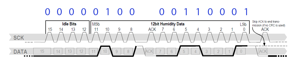
As seen in Figure 4, the ODROID reads the number in two pieces, 00000100 and 00110001. Each of these pieces are called a byte. This occurs over three sections. The first and thirds sections transmit the actual bytes. These transmissions occur bit by bit as the ODROID alternates SCK between 0 and 1 while reading DATA. The second section is another ACK signal. After the first byte is sent, the sensor changes DATA to 1. To send an ACK signal, the ODROID needs to change DATA to 0 and cycle SCK between 0 and 1. This tells the sensor that the ODROID is ready to read the second byte. The number read from the sensor is in binary and needs to be converted to a base 10 number system. Later in this tutorial, we will use software to do this. But for now, note that 00000100 00110001 equals 1073. After a measurement has been recorded and converted to a base 10 number system, it must be plugged into an equation to get the final result. If a temperature measurement was taken, the following equation is used:
T = -39.7 + 0.04xIn this equations, x is the base 10 number recorded from the SHT15 sensor and T is the final result. For example, a value of 1617.5 recorded from the sensor after a temperature measurement indicates a temperature of 25oC. If a humidity measurement was taken, the following equation is used.
H = -2.0468 + 0.0367x – 0.0000015955x2In this equation, x is the base 10 number recorded from the SHT15 sensor and H is the final result. For example, a value of 1073 recorded from the sensor after a humidity measurement indicates a humidity of 35.5%
Using PHP to read humidity and temperature data
After glancing through the previous section, the idea of controlling SCK and DATA pins through the Linux command line to request and read measurements might not sound very appealing. If that’s the case, I wholeheartedly agree with you! To make this more manageable, I wrote two PHP scripts to do the hard work. To download these scripts, navigate to a directory where you want them to be saved, and run the following commands:
$ sudo apt-get install git php5
$ git clone git@github.com:jon-petty/shtx_php_example.git
The first command installs PHP, which is required to run the scripts. The command also installed a program called git, which can be used to download code repositories. The second command uses git to actually download the scripts. If you wish to examine the scripts before you download them, they can be viewed at http://bit.ly/1OGGK5Q. To execute these scripts, first change directories, then follow the instructions in the README.md file. It contains the most up to date instructions on how to execute the scripts:
$ cd shtx_php_example
$ less README.md
Future projects
At this point, you’ve connected an SHT15 sensor to your ODROID and are able to record the humidity and the temperature. You also have an understanding of how GPIO pins are controlled in Linux, and what communication protocol is used with an SHT15 sensor. If you’re curious and want to learn more, I encourage you to take a look at the PHP scripts and match up the code to the communication protocol and equations. You can also take a look at the data-sheet and learn additional things out of scope of this article. For example, if temperatures vary greatly from 25oC, the recorded humidity needs to be run through a compensation equation to make the results more accurate.
References
Datasheet SHT1x. Sensirion, Dec. 2011. http://bit.ly/1x0FfqK
Be the first to comment