

SBC water cooling is not new and others have implemented designs using off the shelf components for the ODROID-XU4 and other SBC. Some implementations have already been covered in ODROID Magazine in the past.
December 2016 https://magazine.odroid.com/wp-content/uploads/ODROID-Magazine-201612.pdf
July 2018 https://magazine.odroid.com/article/liquid-cooling-part-1-cluster/ https://magazine.odroid.com/article/liquid-cooling-part-2-server/
The focus of this project was initially to make water cooling low cost and economical for the ODROID-XU4. After working on the water block design, I discovered a way to support a wide range of other SBCs regardless of their ability to support a proper heatsink. This development was the auspice for the SBC Model Framework that I completed earlier. https://forum.odroid.com/viewtopic.php?f=53&t=33823 Now any SBC supported by the SBC Model Framework can utilize this design to provide a universal low cost water block for a liquid cooled system.
The past water cooled implementations that I have seen used components from the INTEL/AMD desktop arena that were larger and had more capacity than necessary for SBC’s and, therefore, typically had a relatively high cost.
Cooling systems that cost more than the SBC it is cooling are not cost effective or economically justifiable. They are fine for research and special one-off uses but not for widespread adoption. So the first question I had to answer when I started this project was how much cooling cost is economically justifiable?
A lot can be said and has been said on this subject, but for me I arrived at a value of no more than 20% of the total system cost or about the cost of a reasonable heatsink and fan. When I built my ODROID-XU4 cluster, the cost per node, including power supply, SD card and networking, was approximately $73. I wondered if it was possible to build a water cooled system for $14 or less. I already knew it was not possible, if using off the shelf components, so I had to get creative designing new components while looking to re-purpose components from other industries.
There are a host of problems that have to be solved in order to reach all of the goals set out for this project. This article deals specifically with the first phase of the project, a universal water block and attachment method with low cost fittings and pump. The heat exchanger and final packaging of the complete cooling system will be addressed in the second phase. This project is also the first step toward my ultimate goal to design a low cost, scaleable water cooled ODROID-XU4 cluster. I’m using a single SBC to work through many of the design issues prior to a cluster implementation.
After experimenting with several approaches for the water block design, and in consideration that some SBC’s do not have a practical way to attach a heatsink, I started to experiment with a water cooled case that could accommodate different size water blocks and a universal attachment method.
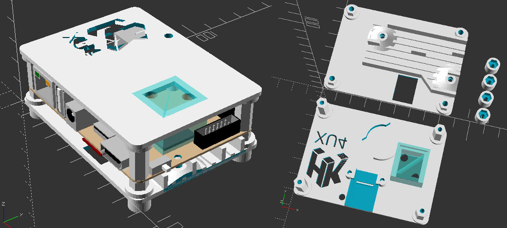
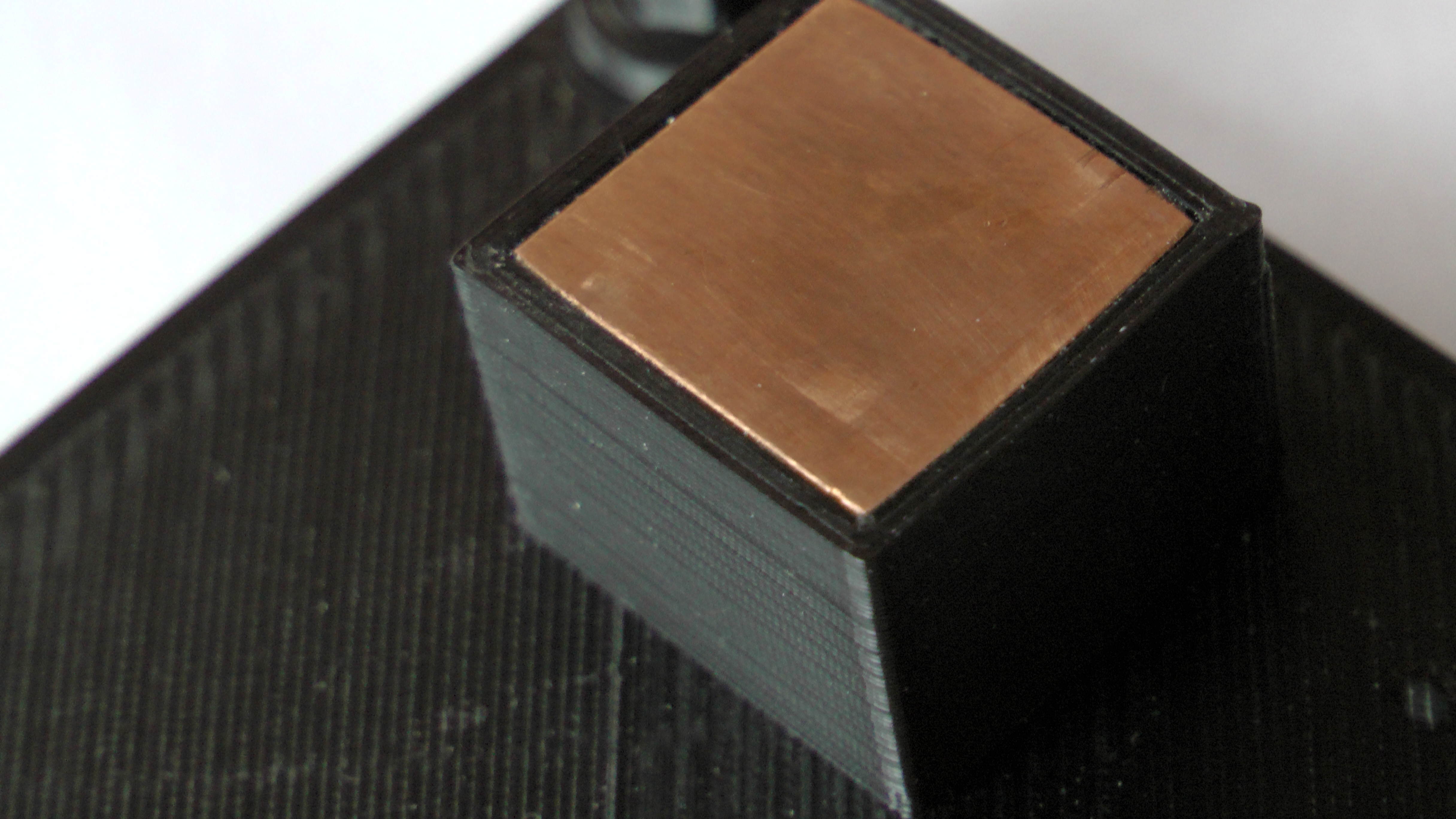
By integrating the water block directly into the case, this approach provided both a way to accommodate most SBC layouts and served as a solid attachment for the water block. The water block could easily be made to any size, shape and allow multiple water blocks on either side of the PCB. With the increasing trend of additional hardware on SBC’s to handle A.I., networking or other specialized processing, I felt it would be beneficial to provide the means to water cool them, as well. It could also provide a way to cool multiple memory chips. A 1/8”(3.19mm) thick piece of copper inserted into the water block is used to transfer heat from the SOC to the cooling media.
Water Cooled Case Design
Some of the additional features of the SBC Water Cooled Case design include:
- Universal SBC Support
- Up to 4 water blocks, top and/or bottom
- Integrated and/or user provided standoffs
- Blind or thru bolted case top with or without countersink
- Predefined accessories (UART holder, RTC holder, ODROID-XU4 case bottom support, artwork, multi-shape fan or cable holes, etc)
- User defined additive or subtractive accessories
Issues and Tips
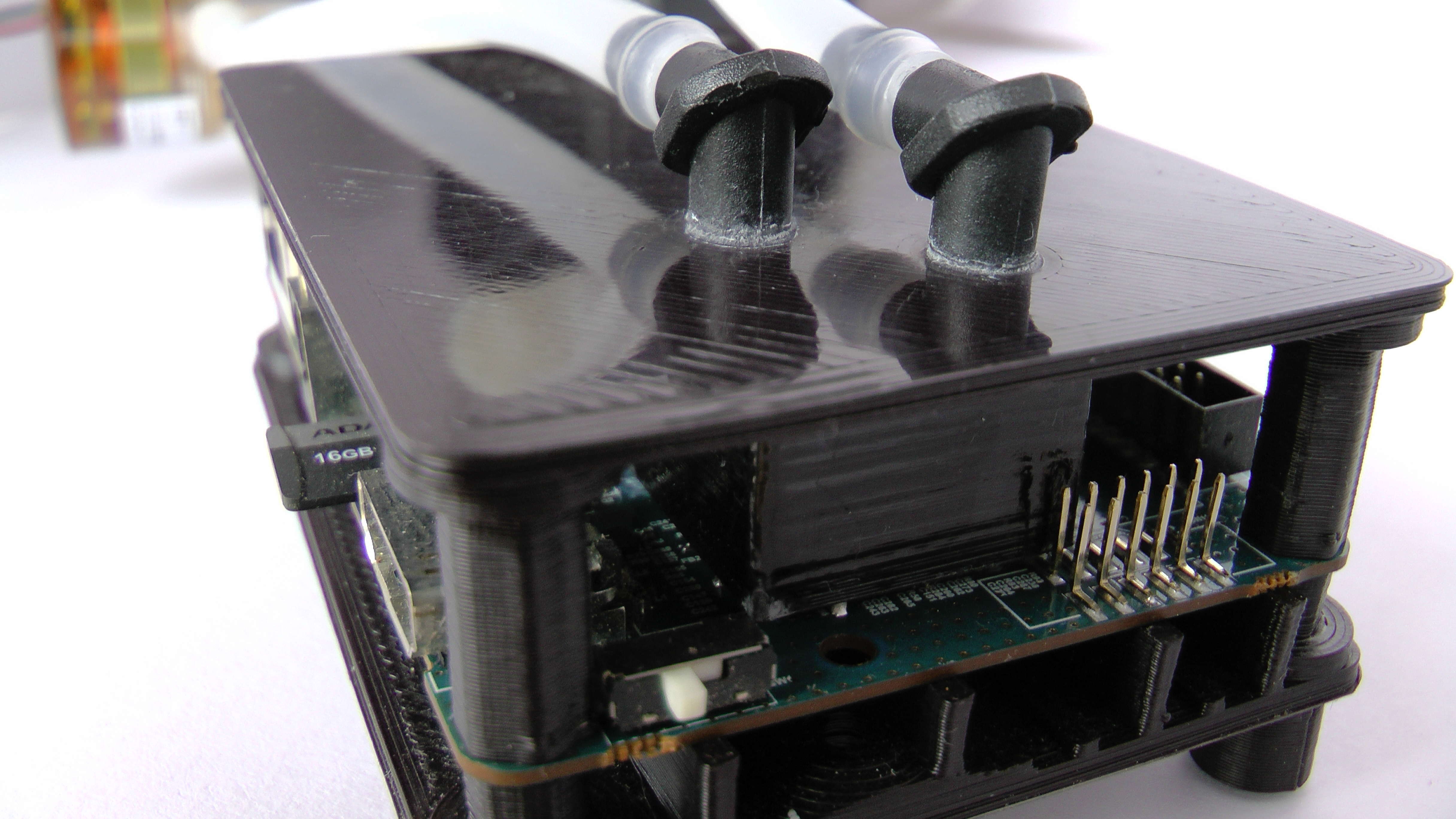
There have been 3 main issues that I have had to work on to bring this design forward. The first was finding fittings that were inexpensive, small and strong enough to work adequately. Fittings from INTEL/AMD liquid cooled systems are too large for most SBC SOC. Two of them will not fit within the size of many SOCs. Being familiar with drip irrigation systems, I decided to use drip irrigation barbs that are both strong, small, can be easily glued in place, and come in straight and 90 degree variations.
https://www.digcorp.com/homeowner-drip-irrigation-products/1-4-barbed-fittings
For testing I needed a strong but reversible method to attach them for reuse. After trying several glues, Cyanoacrylate(Super Glue) seemed to work best. I cut the barb off one end and glued them in place. It was strong enough to hold under considerable stress and the barbs could still be freed due to the glue’s brittleness. Another stronger and permanent glue or ABS acetone weld may be used for the final production. It may even be possible to tap one end of the barb for a threaded solution.
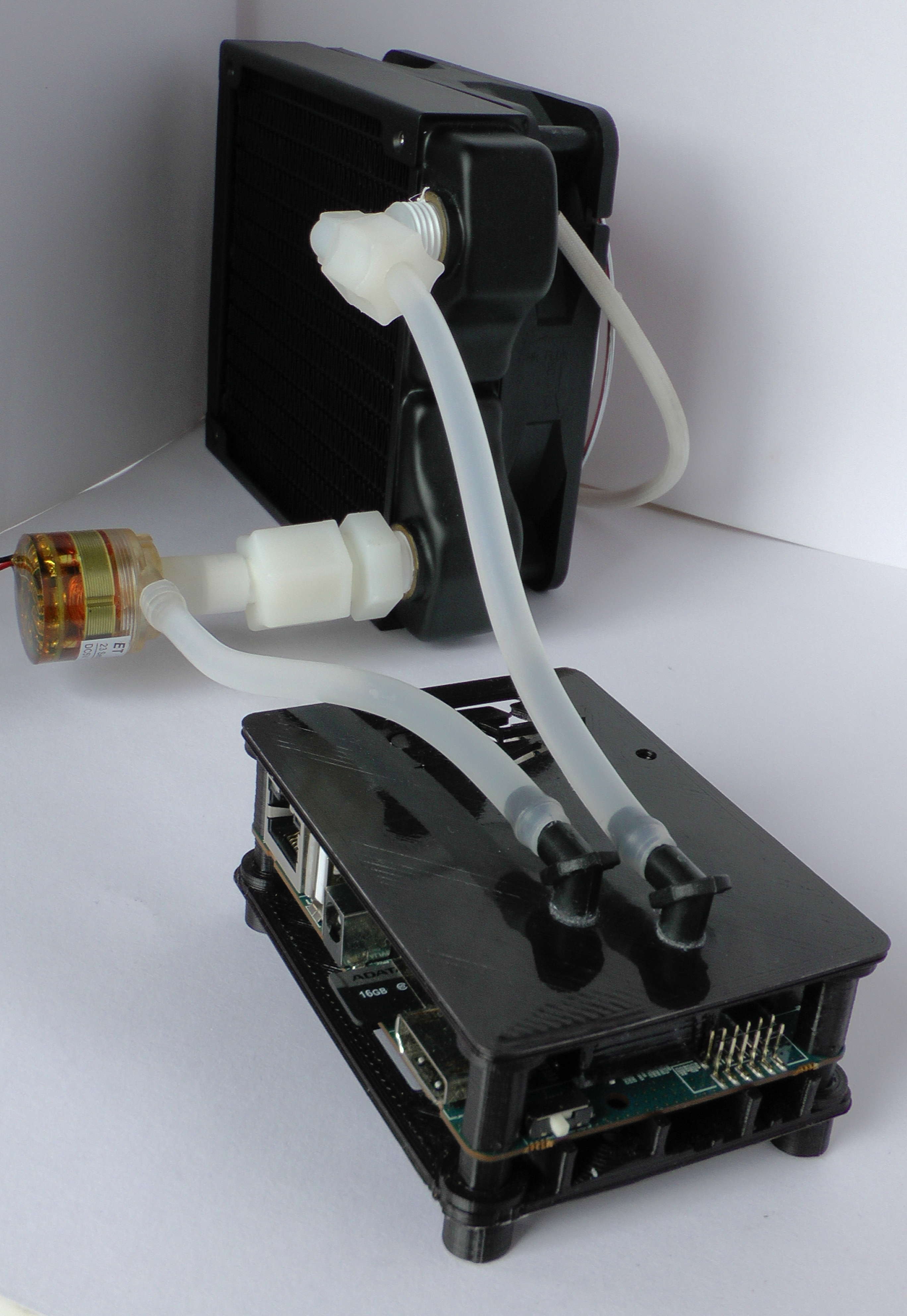
The second issue was finding a suitable pump that was inexpensive, was rated for continuous duty, had an adequate flow rate, and ran on 5 volts. After searching in both the medical and food industries I was able to acquire for $5(delivered), an ET-Tech series 23 5v 1.5w micro pump rated for continuous duty. It also had the benefit of being very quiet. http://www.et-pump.com/brushless_23.html
The third issue to solve had to do with producing the case. The weak point of the design has to do with the manufacturing of the water block using 3D printing technology. Each layer of the water block was a potential water leak. On top of this, the ODROID-XU4 SOC location provided a unique challenge due to its close proximity to the 12 pin GPIO header. Because of the required water block wall thickness, the water block did not have the proper clearance for the connector. None of the other SBCs I tested had this issue, it was specific to the ODROID-XU4. To make things worse, it was close to working but if you forced the assembly of the case, the pressure bowed the top of the case slightly and ultimately created enough pressure to open micro cracks in the print layers that eventually leaked.
Over several months of working on this issue I could not solve it and set the design aside. The design still worked for other SBC but the ODROID-XU4 was the main reason I wanted this solution. After many more attempts to address what I considered a major design issue, I realized that the housing for the 12 pin GPIO header could easily be slide off the pins which allowed enough room for the water block to make proper contact with the SOC. Generally speaking, my overall design approach is never to make permanent modifications to the SBC. I felt this solution was a reasonable compromise since the housing could be easily re-installed. Please note, due to the minimization of solder used in the manufacturing of the PCB and lack of support with the housing off, it is very easy to pop a pin loose, so be careful if you remove the GPIO header housing.
To add some assurance that micro leaks would not be an ongoing problem, I also developed a technique to strengthen the whole water block. Using a cotton swab and acetone, I dipped the swab in the acetone and then rubbed it back in forth across each side of the water block and corners. I repeated this process 2-3 times per side so that the ABS melted and formed a continuous bond across the face, significantly minimizing the chance of any micro cracks forming in the water block. I have not had any leaks using this method. If the case was manufactured with an injection mold, this problem would not exist. It is specifically due to the layered manufacturing process of 3D printing that this issue had to be solved.
One other tip worth mentioning is to dip the 1/4” tubing in boiling water to form any needed curves so that connections are not under stress once assembled. It only takes a few seconds exposure to soften the plastic enough to form any shape you might need and the shape is permanent once the plastic cools. It also makes it easier to fit the tubing over the barbs.
Beta Release of Design
I’m at a point where I can make a beta release of the design even though the heat exchanger is not complete. A lot of radiators incorporate a pump in the radiator so anyone that has an old one from an INTEL/AMD system could create an inexpensive water cooled SBC using this current beta design.
It is not practical to test every SBC and case configuration; it can also include air cooled versions. It has been several months since I did multiple SBC test prints and it was restricted to the ODROID SBC that I owned. No operational testing was conducted at that time.
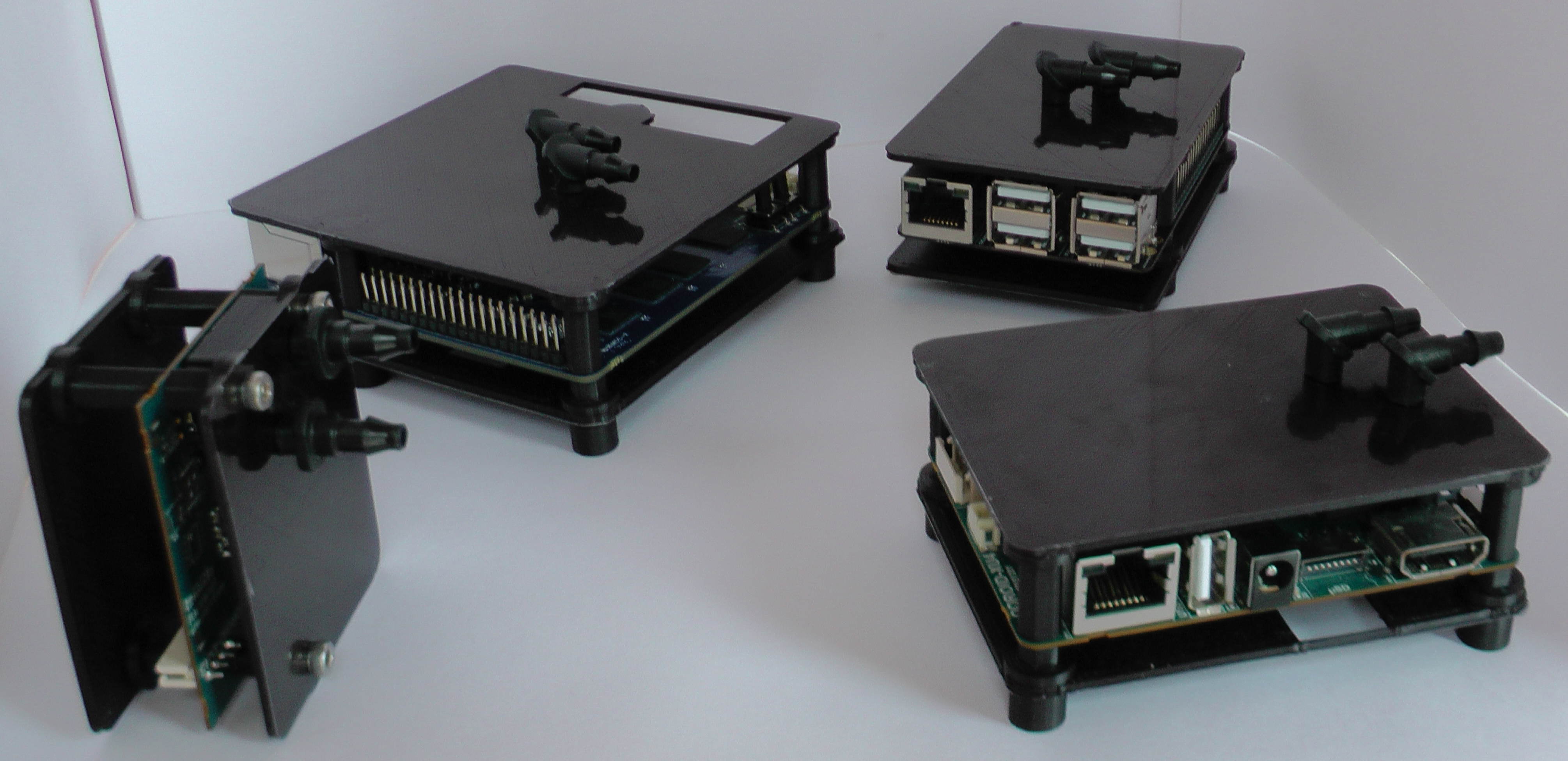
Since then, I have completely rewritten the OpenSCAD case algorithm and added new features. The ODROID-N2 was released and the ODROID-H2 became available again so be aware and please provide any feedback you have if you tried one of these SBC, not that the ODROID-N2 needs water cooling, or a new one.
SBC Water Cooled Case Design Files
The SBC Model Framework is needed and its directory should be installed in the same parent directory as the SBC Water Cooled Case directory. If you would like to use a different directory structure the include and use statements in sbc_water_cooled_case.scad need to be changed accordingly.
use <../sbc_models/sbc_models.scad>
include <../sbc_models/sbc_models.cfg>
The SBC Model Framework can be acquired in the ODROID forum at https://forum.odroid.com/viewtopic.php?f=53&t=33823
Initial Water Block Testing
I did not know how a reduced size water block was going to perform. I do know the ODROID-XU4 has a relatively small SOC, is one of the most challenging SBC to cool when running at 2Ghz, and if It worked. This success bodes well for adoption with most other SBCs, too. After over a year and a half of working on this project I finally arrived at a point to do the initial testing and find out for sure if I was on a workable design. It is not comprehensive testing, that portion of this project will come after the heat exchanger is incorporated into the system.
Test Bed and Operational Parameters
120mm copper radiator and 120mm fan was used for the water block testing using the HK Minimal Ubuntu 18.04 image. All tests were conducted with the A15@2ghz, A7@1.5ghz, memory at 933mhz with Performance CPU and GPU governor settings.
$ uname -a
Linux c2n1 4.14.127-164 #1 SMP PREEMPT Wed Jun 19 17:28:22 -03 2019 armv7l armv7l armv7l GNU/Linux
Kernel compile at 2ghz @ 71F(21.66c) Ambient Temperature
real 25m12.282s
user 172m3.503s
sys 16m48.678s
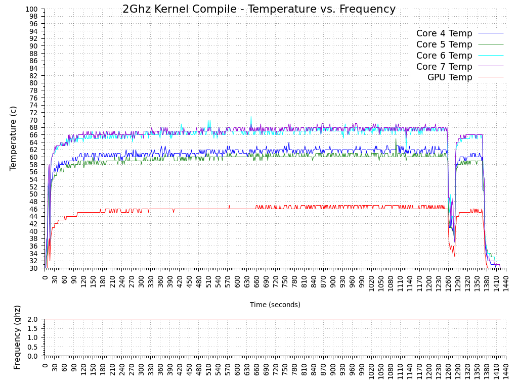
I found it interesting that the compile time was slightly better than the ODROID-H2 cross compile time demonstrated during a recent review at cnx-software.com. https://www.cnx-software.com/2019/07/14/odroid-h2-review-ubuntu-19-04/ The author compared the ODROID-H2 cross compiling of a ODROID-XU4 kernel to an ODROID-XU4Q native compile time. The ambient temperature during that test was higher and unfortunately I don’t have an ODROID-H2 so I cannot duplicate the test to compare the performance with the same ambient temperature. One other note regarding the kernel compile test; after the test completed, I realized that I had been running on a stock kernel that had transparent huge pages enabled. I’m not sure if this helped or hurt the completion time but since it was the thermal characteristics I was interested in I didn’t worry about it. The BOINC test used the same kernel.
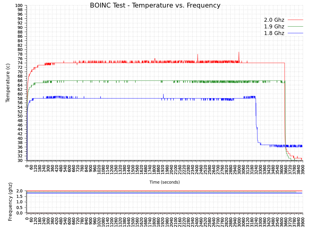
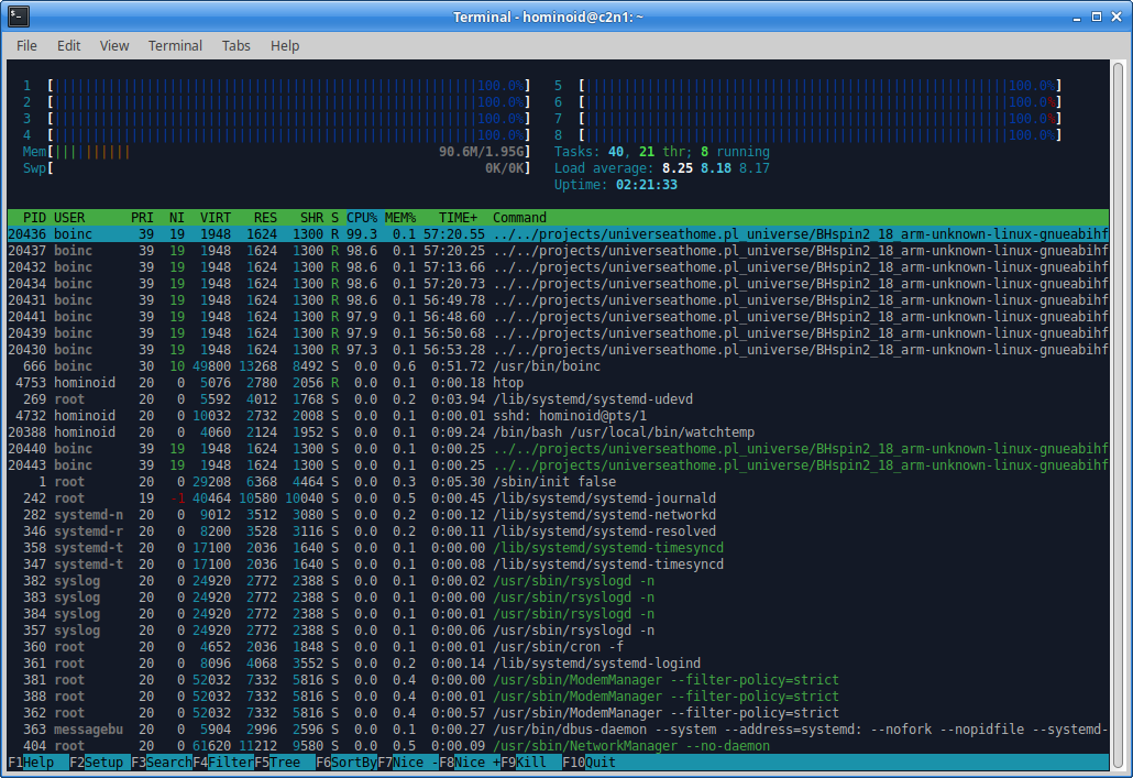
Boinc Test 8 threads @ 72(22.22c) Ambient Temperature
BOINC Universe@home 8 thread workload was used for the following tests at 2ghz, 1.9ghz and 1.8ghz for approximately 1 hour each. The same workload was used by pausing BOINC processing until the SOC cooled down, the clock frequency was adjusted and then the BOINC workload was resumed. As evident from the chart below, two threads finished approximately 10 minutes early during the 1.8ghz test. I believe the results are still valid when considering there was no change in the last 10 minutes of the 1.9ghz or 2.0ghz tests. Looking at the drastic temperature difference once the 2 threads completed, I initially assumed they were both running on A15 cores but after examining the test data closer I couldn’t verify that conclusion because the temperature across all the A15 cores dropped proportionally. This would seem to indicate that it could have been two A7 cores that completed. I would not have expected such a decrease and uniformity in A15 core temperatures if that was the case. I have not done any other analysis or testing to confirm which was the case so it is still undetermined. For simplicity, the chart is of the hottest A15 core for each frequency tested.
Summary
The kernel compile test was able to maintain approximately 68C and the BOINC loads also performed well at the test frequencies. Some small improvements in thermal performance may be possible with the addition of a fluid with better thermal absorption properties, varying flow rate or by fine tuning flow patterns through the water block. I look forward to finishing the heat exchanger design so more comprehensive testing can be done with the complete system.
| XU4 Current BOM | Cost (USD) |
| 1/4” Barbs, ABS $.09 x 2 | $0.18 |
| 1/4” Tubing 1’ | $0.15 |
| 1/8” Copper 15.5mm x 16.75mm | $0.38 |
| Pump 5v 1.5w .5 L/min | $5.00 |
| ABS Plastic Filament, 30g | $0.34 |
| Glue and Electricity | $0.25 |
| Sub-Total | $6.30 |
Of the $14 budget, $7.70 remains for the heat exchanger. I have several designs I’m currently considering. Even though the current pump has performed well, I have also been exploring other options to reduce its size and cost. If this project is successful, SBC water cooling may become economical and expand the thermal envelope by allowing an SBC to run unthrottled in higher ambient temperatures while increasing real world performance of SOC’s using older fabrication processes.
The OpenSCAD design files, test data and gplot scripts are available in the forum at https://forum.odroid.com/viewtopic.php?f=98&t=35751.
Be the first to comment