
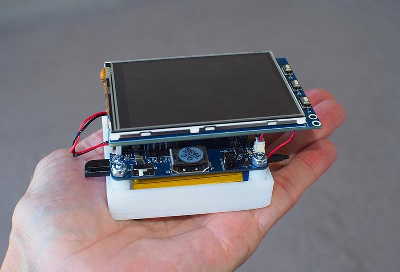
Fresh on the heels of the ODROID Tablet project, https://magazine.odroid.com/article/build-a-rootin-tootin-dual-bootin-odroid-tablet-using-the-odroid-c0-to-make-a-professional-grade-tablet-for-under-usd100/, comes an even more portable version of the ODROID-C0. Rather than sporting a large-scale HDMI-equipped LCD, this “pocket ‘puter” relies on a framebuffer-driven video output displayed on a 3.2-inch thin-film-transistor (TFT) touchscreen shield dubbed the C1.
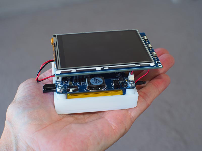
While this touchscreen shield is designed as a simple “plug-n-play” peripheral, the software setup for enabling the ODROID-C0 to use this display can be a daunting task. Luckily, Hardkernel has created a series of articles for enabling you to setup this display quickly and easily. Just religiously follow the Hardkernel wiki steps, while adhering to the following assembly steps, and you will have your very own pocket full of computing pleasure for less than $65.
Parts
- ODROID-C0 $28.00
- C1 3.2-inch TFT + Touchscreen Shield $25.00
- Connector Pack for ODROID-C0 $1.80
- 3000 mAh Battery $1.00
- RTC Backup Battery $2.50 [Optional]
- microSD Card 32GB $5
- Also, you will temporarily need access to an HDMI monitor and USB keyboard and mouse for programming the ODROID-C0.
Step-by-Step
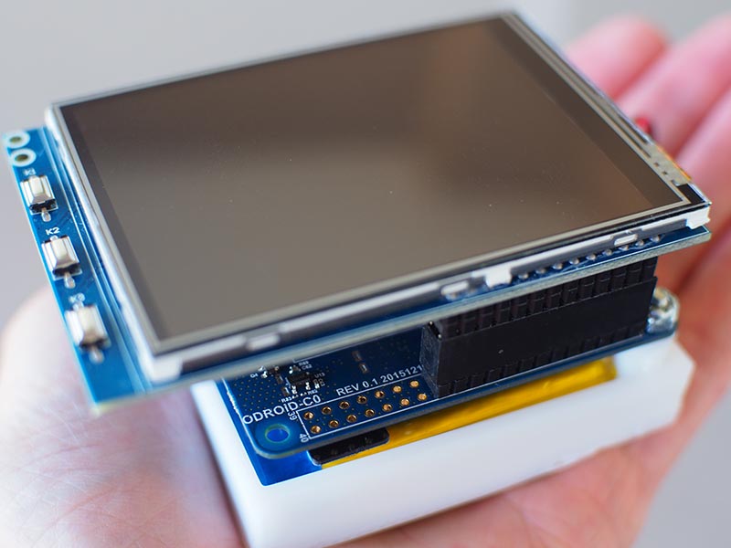
1. Prepare the ODROID-C0 PCB with several components from inside the Connector Pack for using the C1 shield. Solder the dual stacked USB connector to the PCB. Snap off 26 pins, two rows of 13 pins, from the ODROID-C0 dual row header. Solder this header onto the ODROID-C0 GPIO connector starting from pin 1.
(
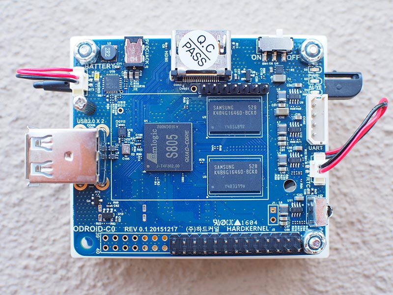
2. Connect the 3000 mAh Battery and the optional RTC Backup Battery to the ODROID-C0.
3. Slide the C1 Shield female headers onto the ODROID-C0 headers you soldered in Step 1.
4. Temporarily connect the ODROID-C0 to an HDMI monitor and USB keyboard and mouse.
5. Ensure that the ODROID-C0 is being powered by a 5V 2A power supply. The PCB’s green battery charging LED may or may not be lit during the programming of the ODROID-C0.
6. Follow the Hardkernel Wiki steps for programming the ODROID-C0:
http://wiki.odroid.com/accessory/display/3.2inch_tft_touchscreen_shield/start
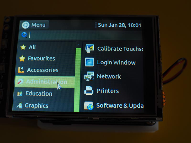
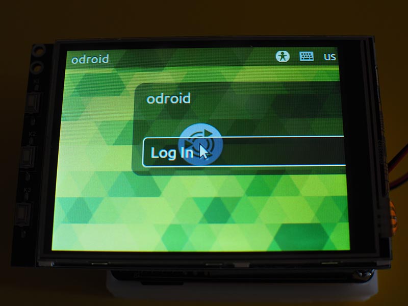
7. Disconnect the HDMI monitor and reboot the ODROID-C0. Keep the USB keyboard and mouse plugged into the ODROID-C0. After a one to two minute delay, the mouse cursor will appear on the Touchscreen Shield followed by the Log-in screen.
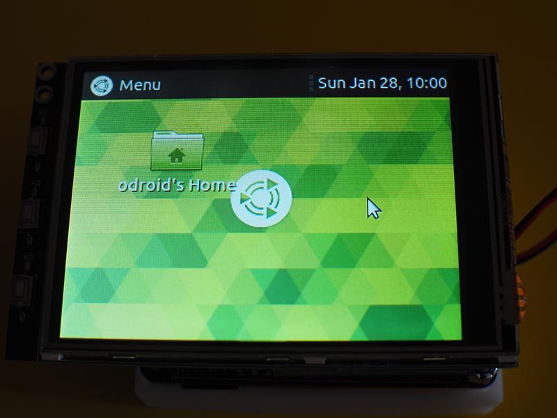
8. Use the USB keyboard and mouse for configuring your new pocket-friendly ODROID. Possible uses for this Pocket ‘Puter are a portable event timer/stopwatch/clock, a family calendar, a mobile download device, and a personal media player.
Notes
1. The large ground, GND, plane on the ODROID-C0 PCB can make soldering extremely difficult. Try using an adjustable-temperature soldering station with a temperature setting of about 380-degrees C.
2. Here’s a Pro Tip for beginning DIYers: never solder more male header pins on a PCB than you plan on using. For example, in this project only two rows of 13 pins were used. If all 40 pins of the ODROID-C0 connector were soldered onto the PCB, some power pins will be exposed (e.g., pin 38 1.8V and pin 39 GND) which could result in a short circuit and damage your beloved ODROID.
3. Add a shutdown button to the top panel of the Desktop window. You can add this button by performing a right click with your mouse while the cursor is inside the top panel.
4. Make two modifications to the Preferences of the File Management app: first, change the behavior of the user interface to using “one click” for accessing files and folders. Second, decrease the magnification of the standard view to 50%.
5. The title for this article is a paraphrase quote of Mae West from the movie “Sextette” (1978).
Be the first to comment