

This series will teach you how to assemble the basics of a retro gaming console using Monku and an ODROID-C1+ / C2. This first installment will show you how to build the custom buttons and controllers for the project.
Tools Needed
- A small screwdriver set that contains various small phillips head screwdrivers.
- A soldering kit including soldering iron with fine tip, solder with flux, temperature control, if possible.
- Masking tape or painter's tape.
- A clean static free work surface.
- Drill and a good selection of drill bits.
- Monitor or TV with HDMI support to test the device.
I used this soldering kit (https://amzn.to/2Jyy85h). It costs around $19.00 and although on the cheap side, it comes with everything you will need for this build and the soldering iron comes with multiple tips including a fine tip and has a temperature control which is awesome. Now I had not soldered anything since high school and I was able to do this and not mess it up. I also do not have the steadiest hands as I have probably had about 3 cups of coffee before any given moment in time. If I can do it, you can do it.
1: Parts Needed
- ODROID-C1+ / ODROID-C2 x1: $35.00 / $46.00 (https://www.hardkernel.com/shop/odroid-c1/)
- Case x1: $4.50 (https://www.hardkernel.com/shop/odroid-c2-c1-case-black/)
- Button Set: $7.99 (https://amzn.to/2HNRekI)
- Breadboard Cable Set x1: $7.99 (https://amzn.to/2wgeXo8)
- 64GB Micro SD Card x2: $16.99 (https://amzn.to/2JyNjLZ)
- HDMI Cable x1: $1.00 (https://www.hardkernel.com/shop/hdmi-1-4-cable-type-a-a/)
- Micro USB Cable x1: $1.50 (https://www.hardkernel.com/shop/micro-usb-cable/)
- USB Charging Block 5V/2A x3: $11.99 (https://amzn.to/2VXIfY0)
- GameSir Wired Controller x1: $17.00 (https://bit.ly/2JxEu4V)
The total project cost as described above and not including shipping or needed tools is around $104. If you exclude the custom control buttons or can buy the parts individually, however, you can save around $16. Also you do not need two micro SD cards. I like to have a spare in case one is corrupt and the dual set listed above has a great price. Also, the card is well rated and from my personal experience I have only had one fail unexpectedly out of 12 or so I have been using regularly during the configuration and development of these devices. If you have an HDMI cable, a micro USB cable, and a USB charger 5V/2A then you can save even more on the cost of this project. While the price listed is around $104 you can probably get it done for around $80. Not too bad, once you see what these things can do.
2: Introduction and Tutorial Goals
This article will show you in detail how to build a Monku Retro 1 (ODROID-C1+) or Monku Retro 2 (ODROID-C2) video game console from scratch. First, some of the hardware basics: the hardware button provides a hard reset of the device. The software button hooks up to GPIO pins and is setup to record how long it is being held and execute a certain command for the recorded time period. So, for instance, a 2 second hold is a software reboot, a 4 second hold is a software shutdown etc. If you do want to add custom control buttons we will cover that here in detail. Everything from the parts, to the pins, to how to solder it all up. This feature is optional. Your device will work fine without them but in the event of a crash you will have to power cycle the console by hand and this action could corrupt the Linux file system. The hardware reset button makes this a little easier, but the software control button with it's OS shutdown and restart calls are much safer to use. You can always go back and add them in, not a problem. We will also cover the software setup including installing and configuring Ubuntu, retroarch, and antimicro in part 2 and 3 of this tutorial series.
R1 / C1+ Features:
- ODROID Goodness
- Custom Software Control Button
- Custom Hardware Reset
- Support for Atari 2600, Atari 7800, ColecoVision, MSX-1, MSX-2, NES, GameBoy, GameBoy Color, Sega SG-1000, Sega Mark III, and Sega Master System configured and ready to go
- Retroarch with XBM, custom scripts to monitor the software button, start retroarch, maintain antimicro
- Configured for low memory usage and for use with included controller
- Every ROM tested to see if it loads and properly associated with its emulator
- Full linux desktop environment when not in game kiosk mode via antimicro
R1 / C1+ Software Button Functions:
- 02 Second Hold: Software reset
- 04 Second Hold: Software shutdown
- 06 Second Hold: Turn off game kiosk mode
- 08 Second Hold: Change to 1024x768x32bpp resolution and reboot
- 10 Second Hold: Change to 720px32bpp resolution and reboot.
R2 / C2 Features:
- ODROID Goodness
- Custom Software Control Button
- Custom Hardware Reset
- Support for Atari 2600, Atari 7800, Atari Lynx, ColecoVision, MSX-1, MSX-2, NES, GameBoy, GameBoy Color, Virtual Boy, SNES, GameBoy Advance, WonderSwan Pocket/Color, NEO
- GEO Pocket/Color, Sega SG-1000, Sega Mark 3, Sega Master System, Sega Genesis, Sega GameGear, NEC Turbo Graphics 16, and NEC Super Graphics emulators configured and ready to go
- Retroarch with XBM, custom scripts to monitor the software button, start retroarch, maintain antimicro
- Configured for low memory usage and for use with included controller
- Full linux desktop environment gamepad control when not in game kiosk mode via antimicro
R2 / C2 Software Button Functions:
- 02 Second Hold: Software reset
- 04 Second Hold: Software shutdown
- 06 Second Hold: Turn off game kiosk mode
- 08 Second Hold: Set video to auto for VGA mode, possibly alter retroarch.cfg for USB audio if present
- 10 Second Hold: Set video mode to 720p, alter retroarch.cfg for HDMI audio
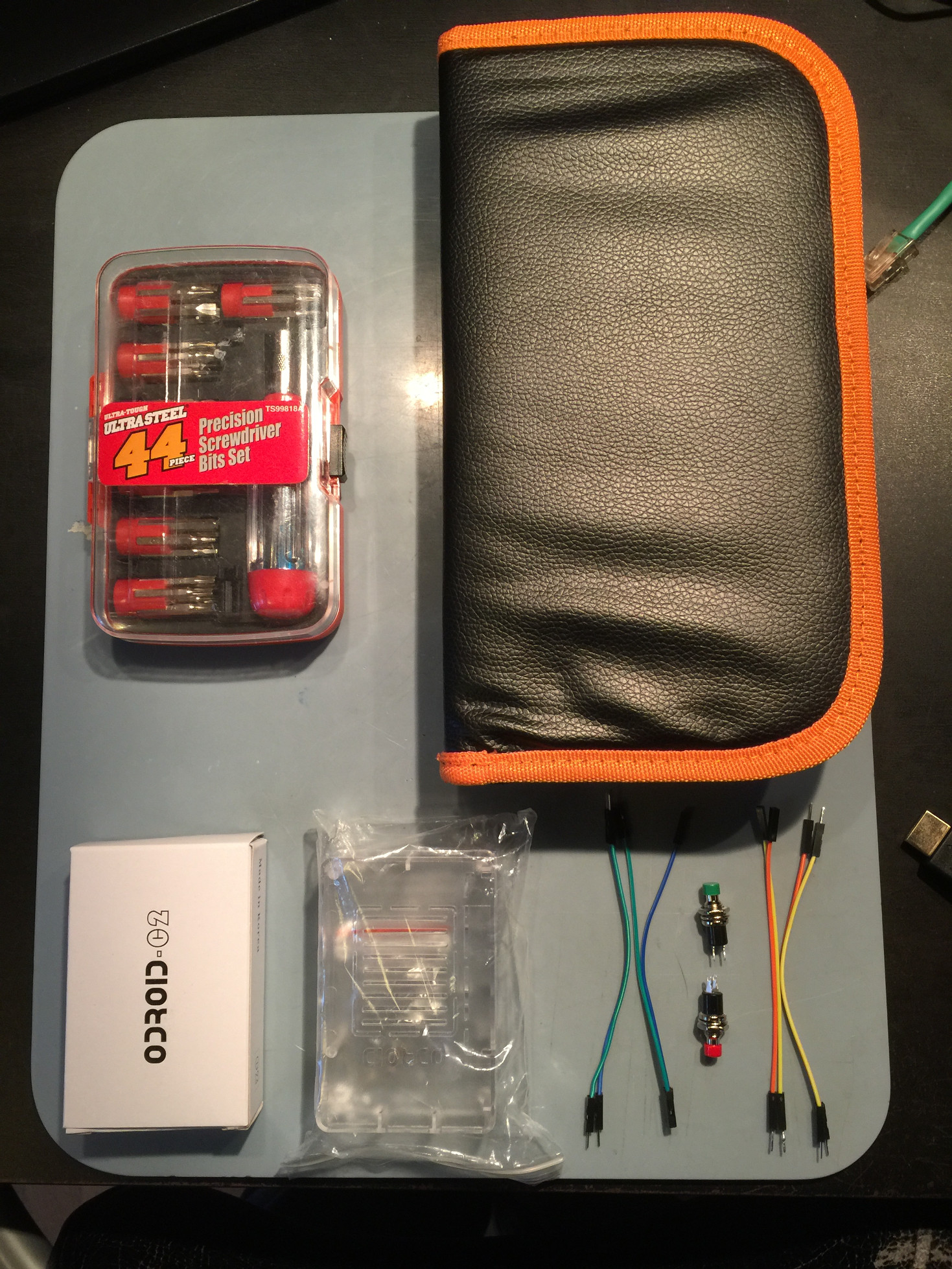
3: The Setup
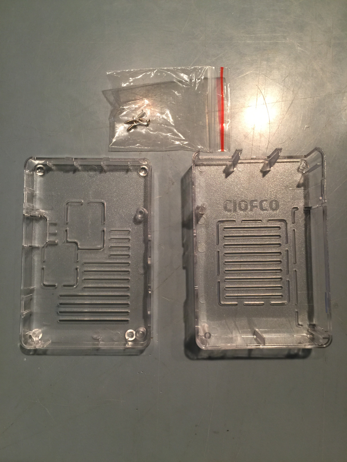
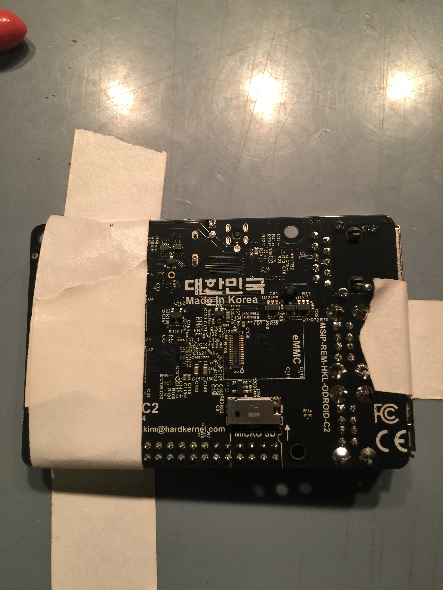
First things first - let’s go over the tools and parts, lay them out, and get ready to build. We have an electronics screwdriver set. If you have built an ODROID-GO the same screwdriver set should work fine here. Notice we have our device, an ODROID-C2 is depicted below, this tutorial applies equally to the ODROID-C1+ or the ODROID-C2 version of this device. The ODROID-C1+ I use for 8-bit retro gaming the ODROID-C2 I like to use for all 8-bit and 16-bit systems plus the handhelds--it runs them wonderfully. You can probably run them on a C1+ but I like the C2 more for 16-bit games, for some reason. We have our custom control buttons, jumpers, case, and tools all ready to go.
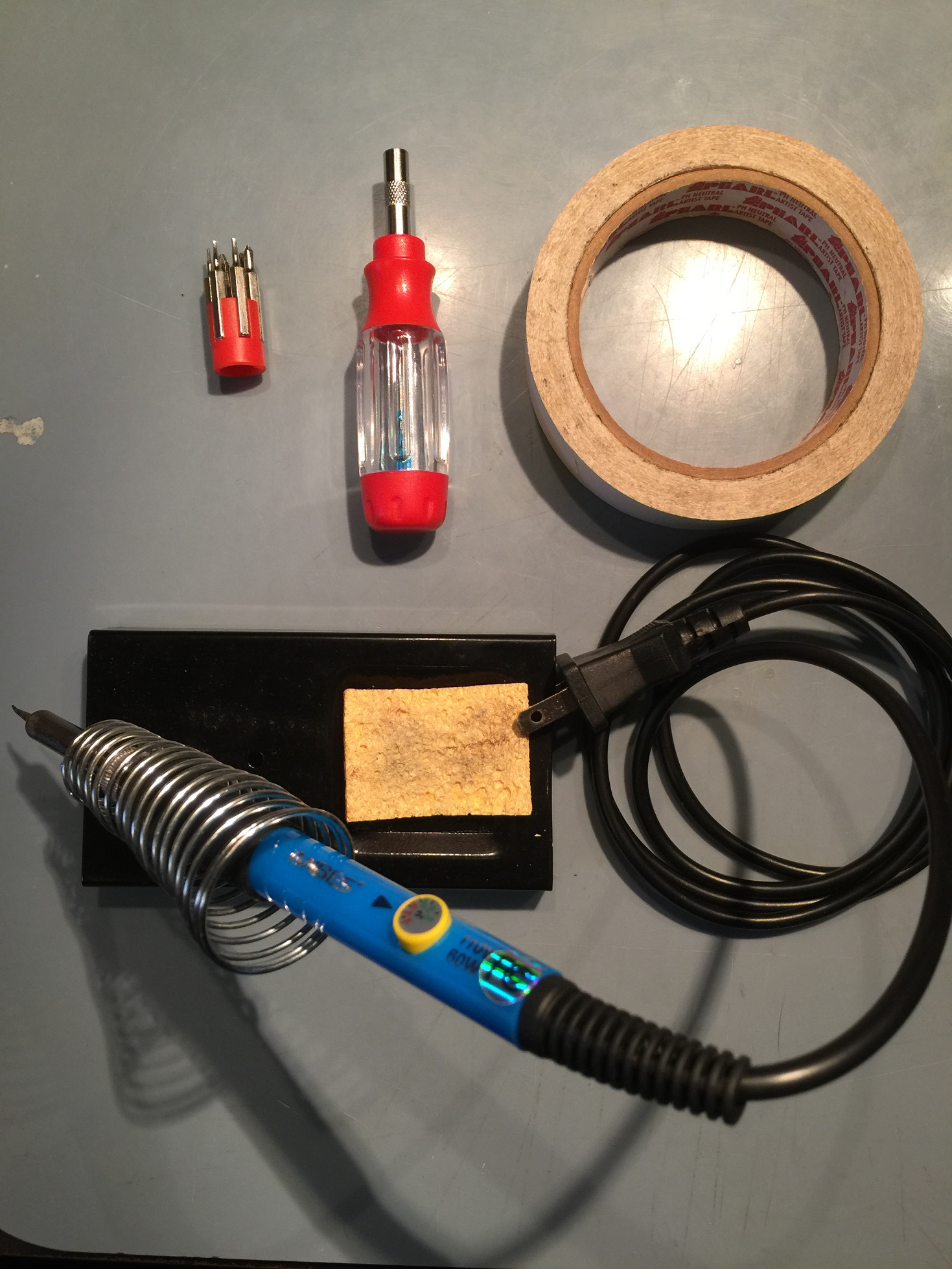
We have our soldering iron, notice the stand and sponge for cleaning the iron and temperature control on the iron. The temperature control is crucial, I think, but you can probably get away with not having one especially if you are good at soldering. The temperature control lets you adjust things so that you are applying high heat for a small amount of time. I have read a few tutorials and watched a few videos and from what I gather lower heat for a long time is not as good as high heat for a very short period of time. I do feel that it makes things cleaner, I am not sitting there trying to hold the iron to a connector waiting for a glob of solder to finally melt. One other thing is you really need is a fine tip on the iron. Again if you have skills maybe you can get by with a different tip, but I do not and a fine soldering tip was a life saver for me. Tip: If you do not have a fancy circuit board holding device to aid you in your soldering I have found that masking tape works really well. Ok, so it will melt, but it should not be getting hot. I will show you how to use the tape to secure what your soldering so you can get a good clean solder joint. It works just as good as the fancy circuit board holders, is super cheap, and has more flexibility. If you really wanted, you could solder upside down, hanging from the ceiling if you use enough tape.
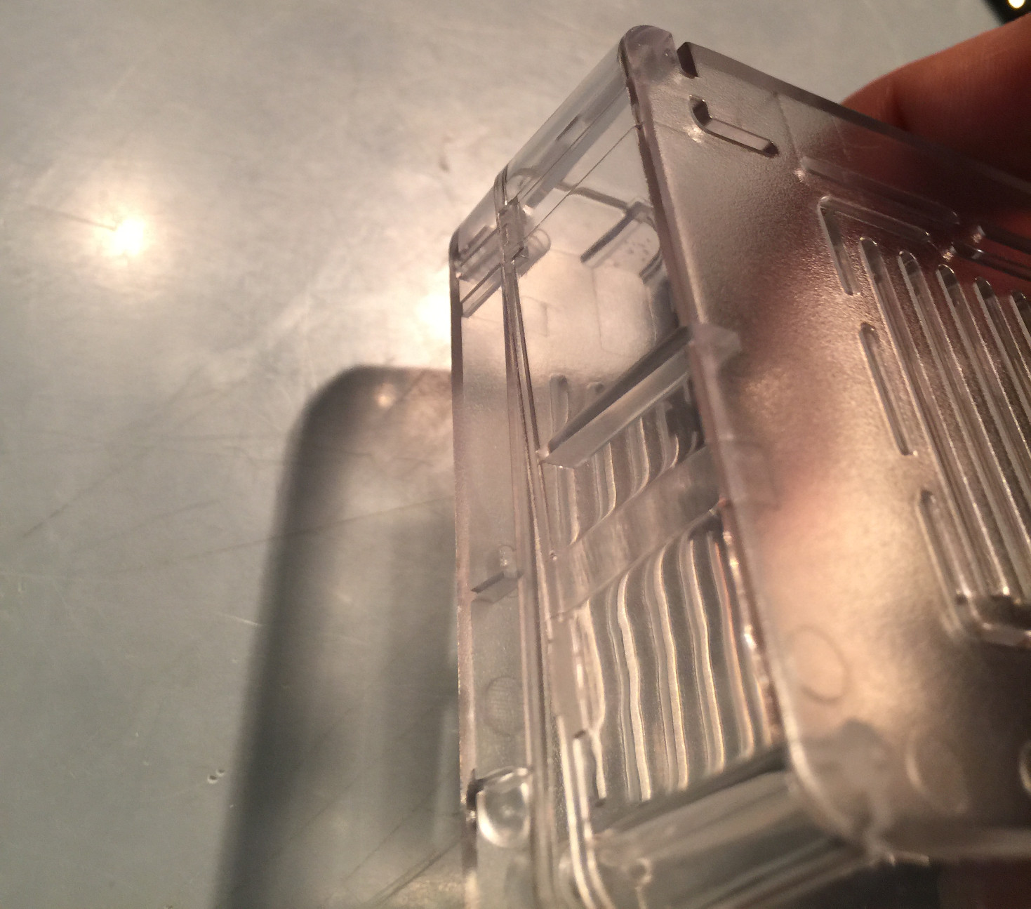
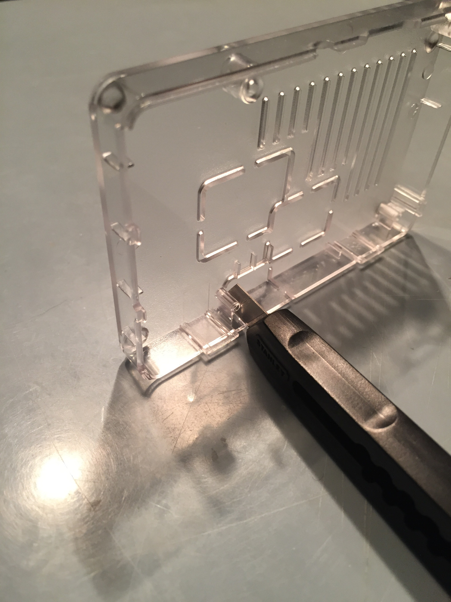
The case can be a little tricky to open. It should require little to no effort to separate it but it takes a little trick or two to do it that way. You could pop it open I suppose but broken fastening clips really irks me so I take the careful route. The first thing you want to do is unclasp the back of the case. This can be done by applying a slight pressure on the bottom of the case pushing it to the right, while pushing the top of the case to the left with a slight lift as shown below. Small forces here, it will not pop open, but it will separate.
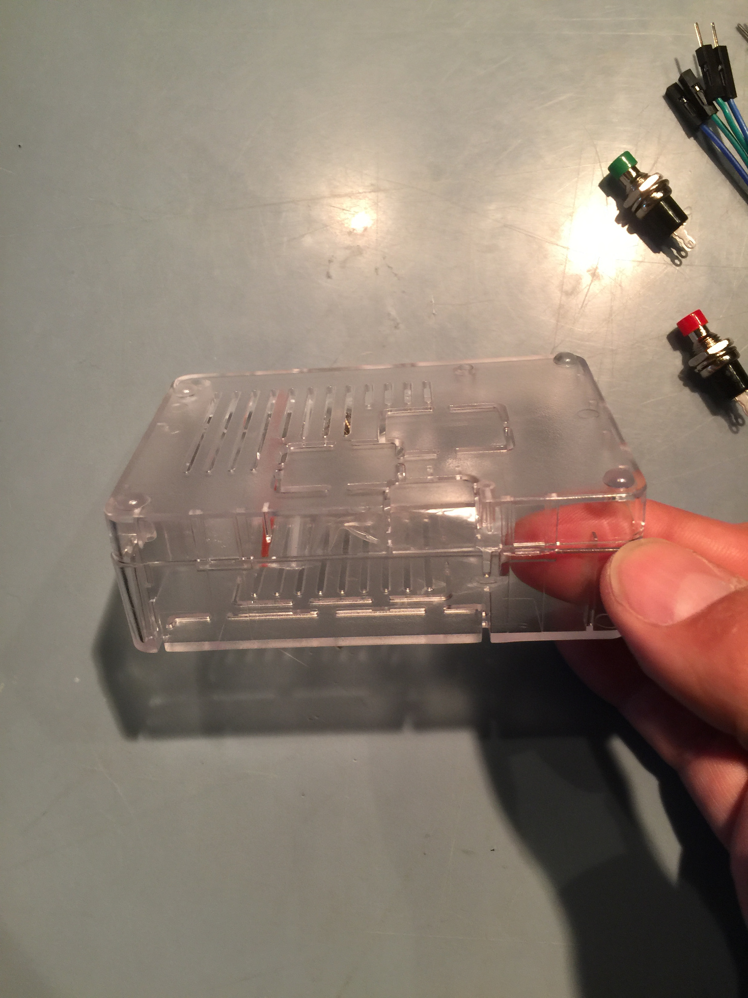
Once the back clip is separated we can move over to the side that has two clips. Tip: The next two clips on the side are a bit tricky. You can get the front one open by putting your finger inside the case and applying the same small forces we used to get the back clip open. To get the last clip on that side open you will need to use your fingernail. Slide the fingernail into the seam on the case at the back clip, the first one we separated, you can drag your fingernail around to the side that has the two clips and it will separate the remaining clip. It takes a little doing, but do not worry take your time. You may inadvertently reconnect a clip; that’s OK, just start over. Main thing here is to have a non-broken case to house our beautiful console.
Now that we have the case open you can access the prize inside, a small bag of screws. Tip: If you have any left over ODROID-GO screws they are slightly bigger than the included screws and I find that they work better and are less prone to stripping. Now that the case is open we have to make a decision about the SD card door Normally the case will have no SD card access unless you pop out the SD card door. So, if your console is all closed up and your SD card dies you will have to very carefully cut open the SD card door or wrestle the case open. I like to open the SD card door for development models so I can easily pop in and out SD cards.
To cut out the SD card door you'll need a razor or small sharp knife. There is not much too it. You will need a few minutes, there is no super fast way to pop it out without risking damage to the case. Scratch away at the connection point with the razor. Drag it across the points one at a time scratching and cutting into the small connection plastic. Tip: You can place the bottom of the case standing up on its side, that way you can put a lot of downward pressure on two of the SD card door’s plastic connections without risking damage to the case. An open SD card door is depicted below on a Monku Retro 1 (ODROID-C1+).
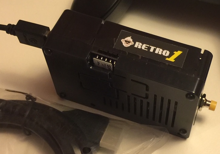
A quick aside, below is a photo of a completed Monku Retro 1 (ODROID-C1+) with custom control buttons and jumper connections. I like using 4 jumpers per button, I know you can get by with only two but I like having the extra connections.For this option, you'll need 4 female to female jumpers, and 4 anything to male connectors. There are other combinations just make sure you lay out the jumpers and envision their use. Make sure all the connections match up. You will have to cut off one side of the jumpers for the wires that are soldered to the buttons.
4: The Soldering
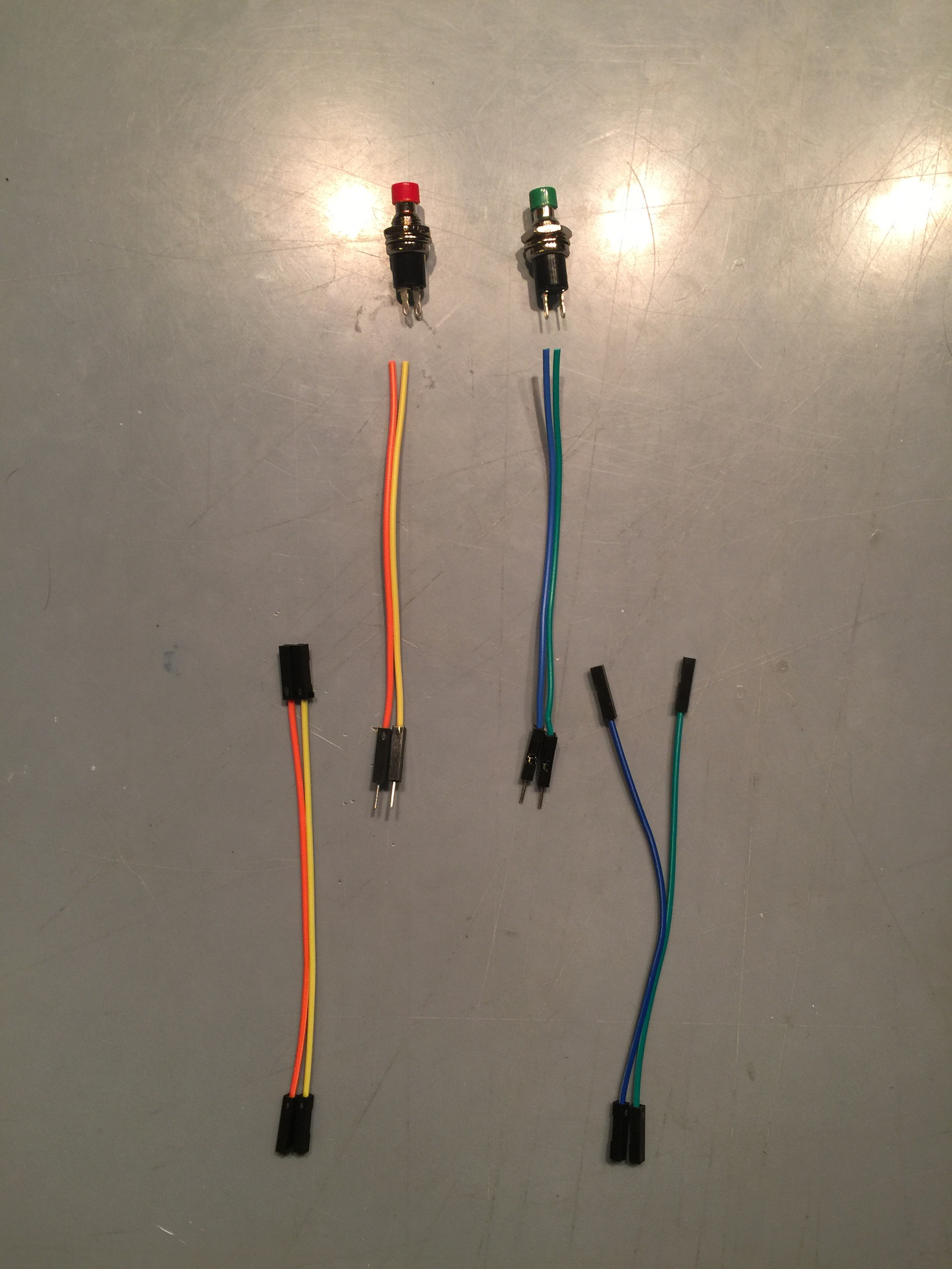
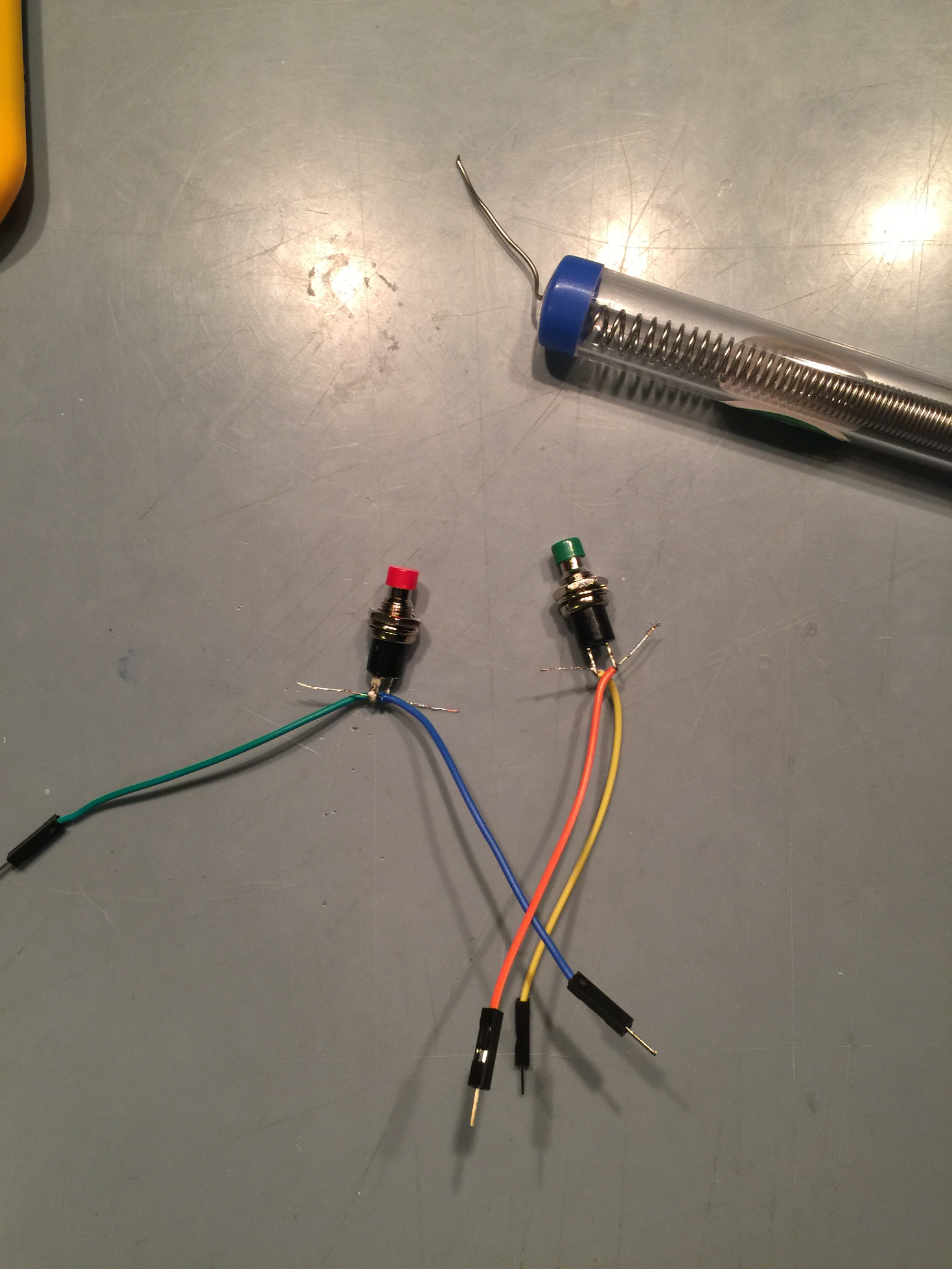
Ok so now we will be getting ready to solder the connection we need for the hardware reset, direct power toggle of the board. Now would be a good time to get your soldering iron. Plug it in and let it get all heated up.We will be using around 400 degrees, if you have temperature control, for the wires and buttons. We are going to layout the jumpers and buttons below to visualize them. I normally use jumper pins from the ODROID-GO expansion slot but I realize not everyone has those, so I used jumpers on this build. In this photograph, I used the wrong colors, oops.
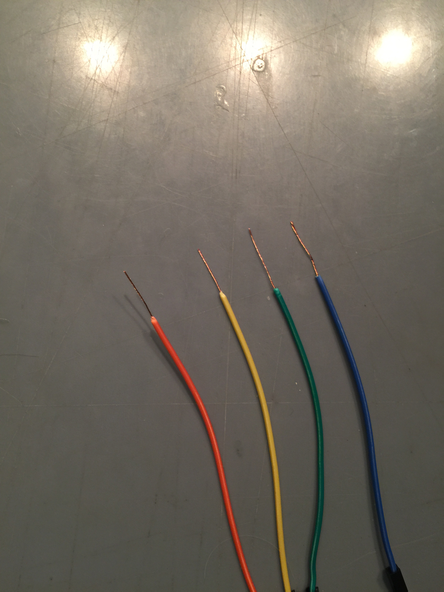
Let’s take the jumpers that are closer to the buttons as shown above. We then cut the connectors off the one side. Now you can use a scissors or your fingernail to remove the wire casing. Either gently roll the wire along one blade of your scissors with a little pressure until there is a break in the casing. Same strategy applies to using a fingernail. Once the casing gets a little white and shows signs of coming apart you can usually pinch and pull just the casing off of the wire. Once that is done hold the very tip of the copper wires and rotate the cable so that they are all nicely twisted up. Do this for the other jump cables as well.
Make sure to check the status of your soldering iron. I accidentally started melting the plastic case on my screwdriver set once during a build. Lay out the four wires and two buttons. Get your iron ready, clean the tip with your wet sponge and tin the iron with a little solder and flux. I will assume you have solder with the flux inside it from this point on We are going to tin all the connections here before we connect them. Solder binds almost instantly to properly tinned connections. I do not tin the boards though, I follow a "as little time with the iron as possible" mantra with the board itself. Notice we are using the masking tape to secure each piece.
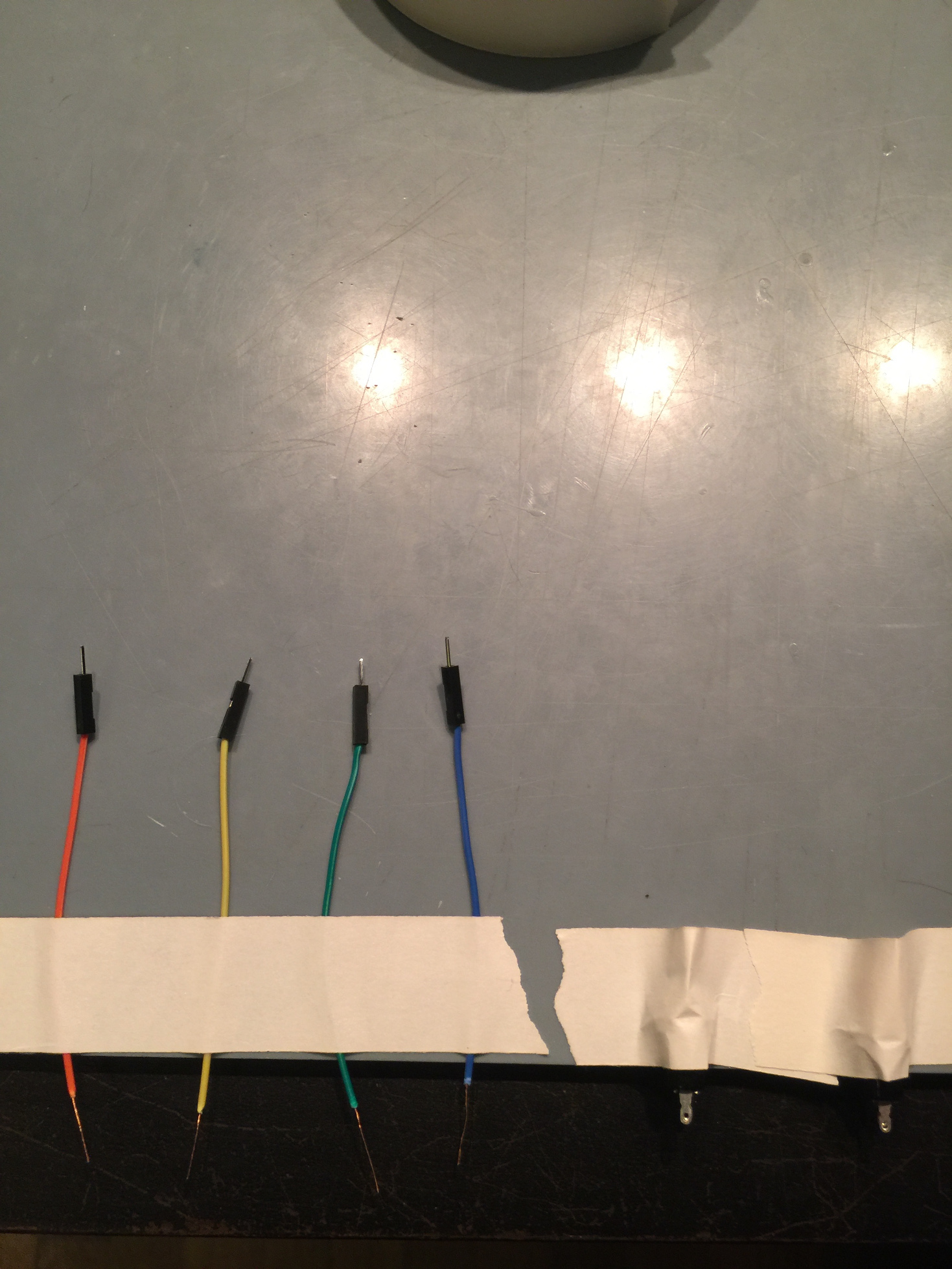
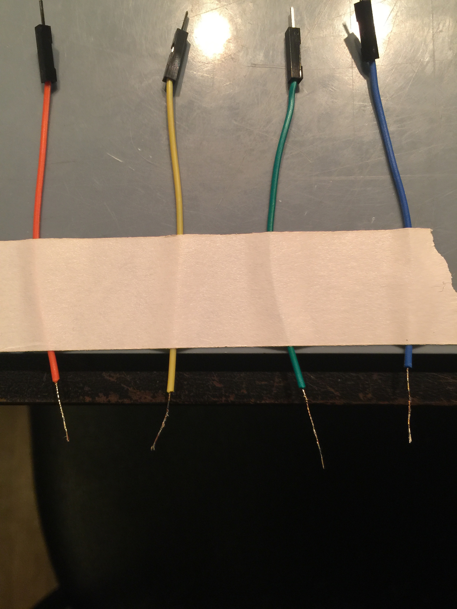
Hold the soldering iron underneath the wire and just dab the solder to it, the copper braid will absorb the solder and you can spread it by moving the iron down the wire. You do not need a lot, just a little on each one Do all four wires.
Now you want to tin the button contact points. Don’t worry if you fill one of the holes on the contact point, it will not be a problem.
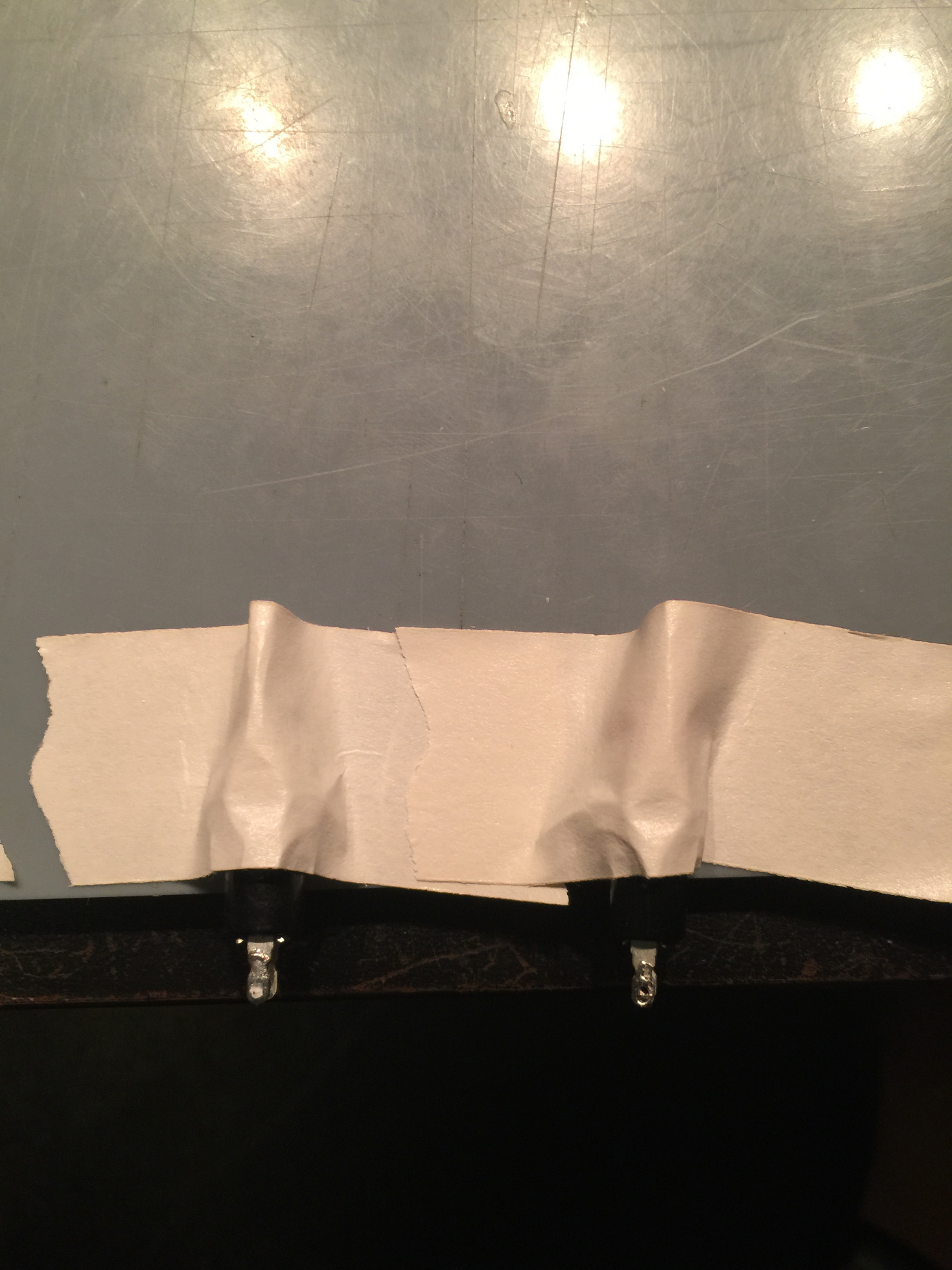
Place one of the wires that we stripped and tinned, keeping the colors you choose consistent throughout the construction, inside the contact hole of the button. You may have to apply the iron slightly to allow the wire to pass through. Bend and secure the wire to the side of the button with some tape. Now solder the contact point. Do this for both connections on both buttons. Use a scissors to snip off the excess wire. You should have something like what's shown below.
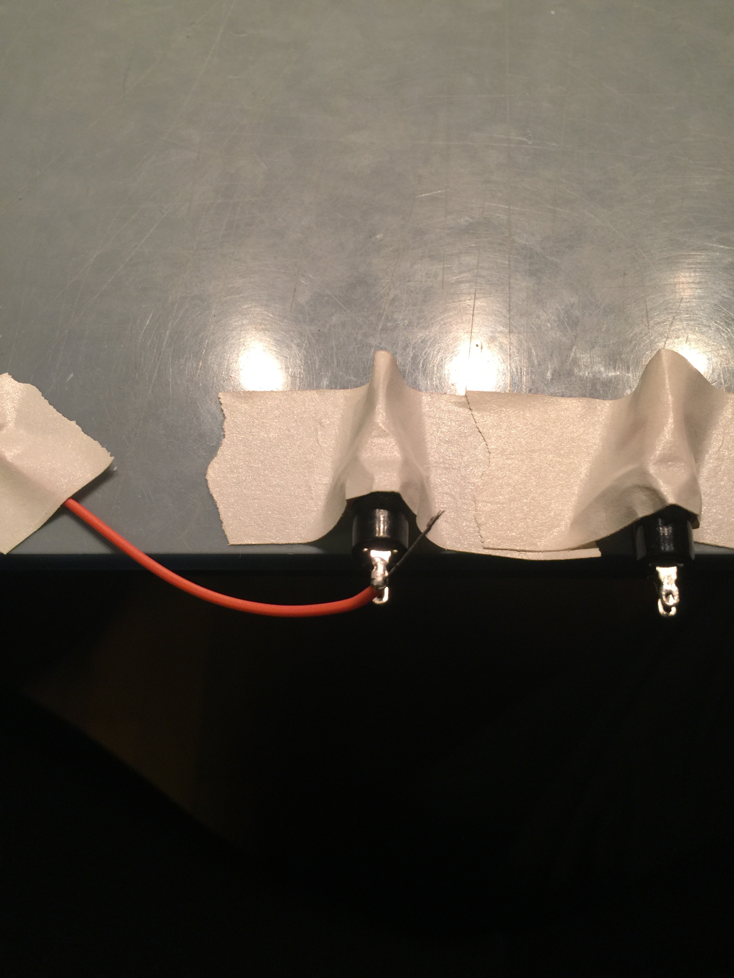
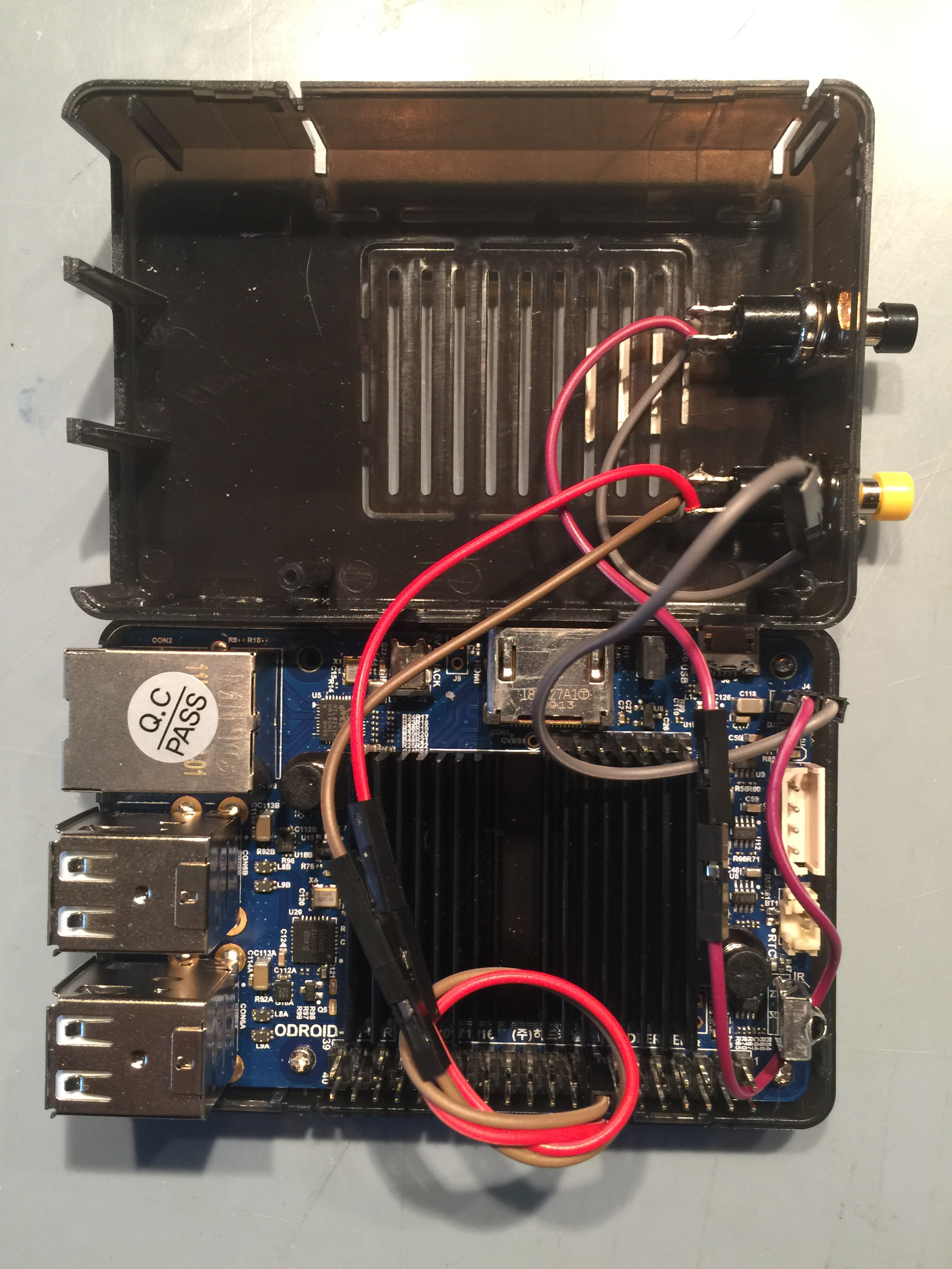
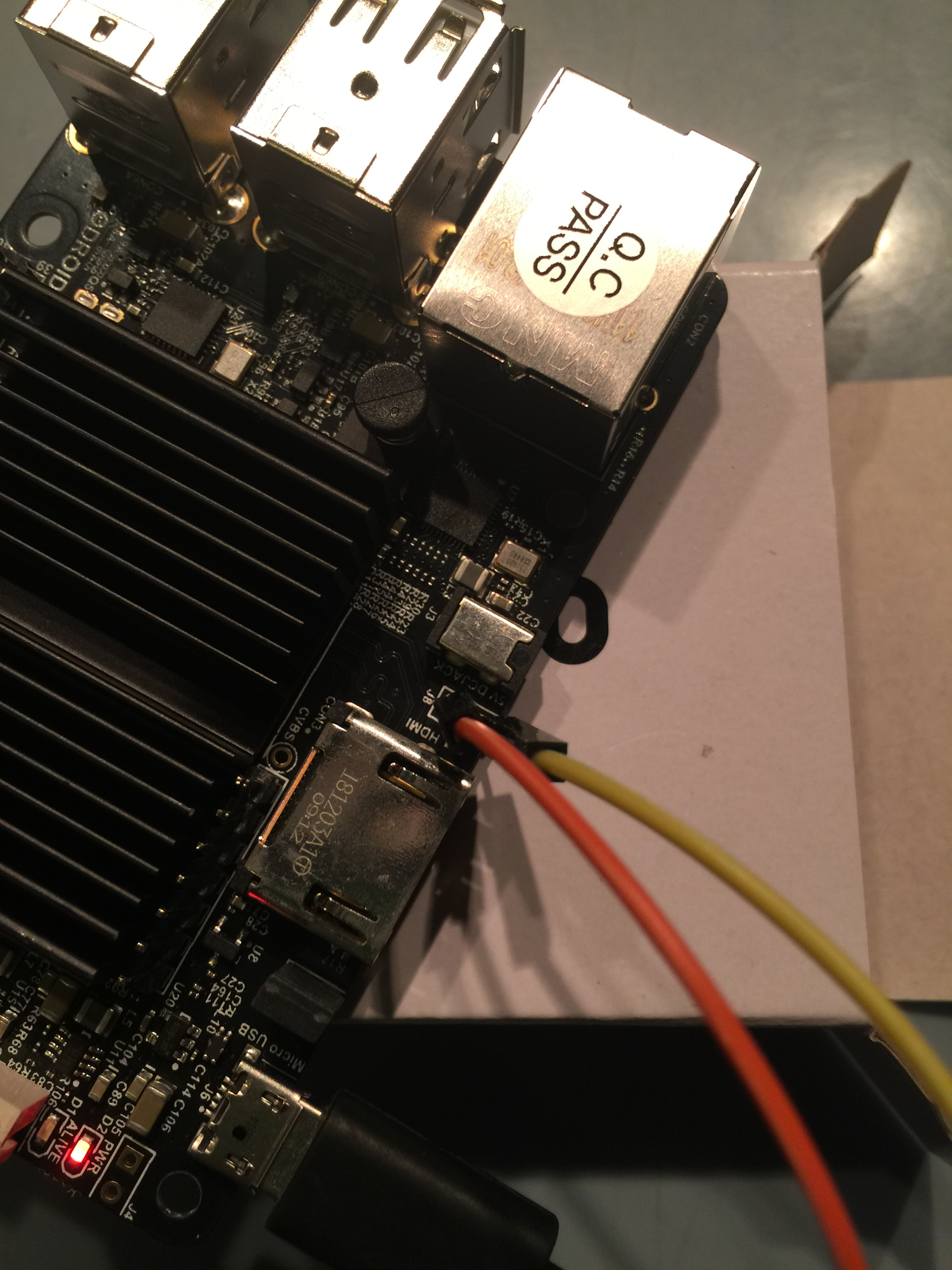
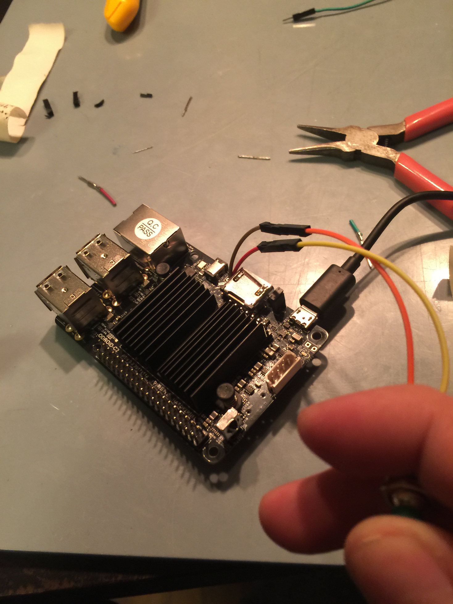
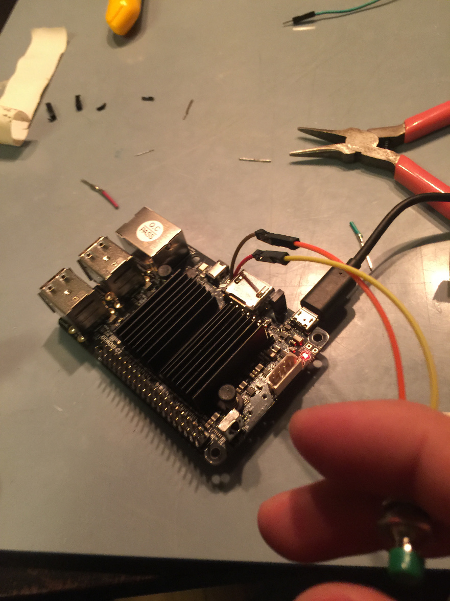
ALERT: There is a difference between the C1+ and the C2 so you have to stop at this point and double check which board you have and in the case of the ODROID-C2, which version of that board. Below is a photo of the C1+ with power button soldered on the board by the "pwr" text. The C2 board has the same marking but it may not be the actual power button location. You can use the buttons you just made to find out which location is the power button point. Place the male jumper leads into the holes in one of the available positions, J8 or pwr, give them a slight squeeze with your finger so they make contact. With the power on, but no SD card or anything in, push the button. If the red LED goes off you've found the power button. If nothing is happening you might have a bad button try the other one you made. If still nothing is happening you might have a bad contact try and short the two little holes at the available locations until you identify which one controls the power.
NOTE: If you are working with an ODROID-C1+ this is the place on the board you will be adding the jumpers for the power switch. Make sure you have verified it with the process outlined above.
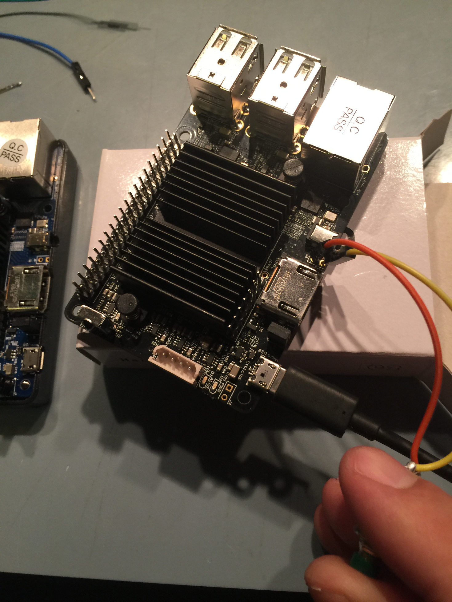
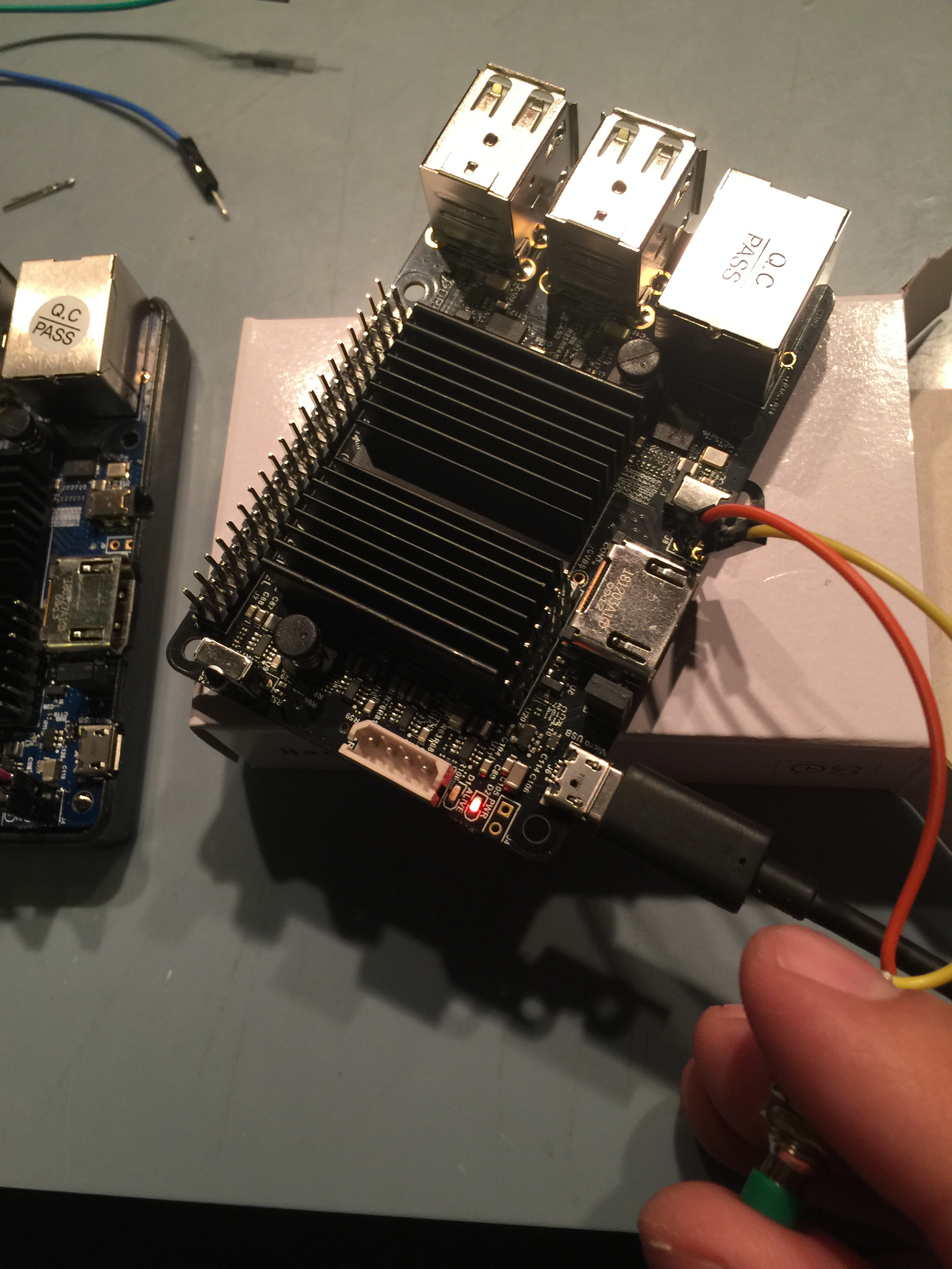
The photos below show the button test in action.
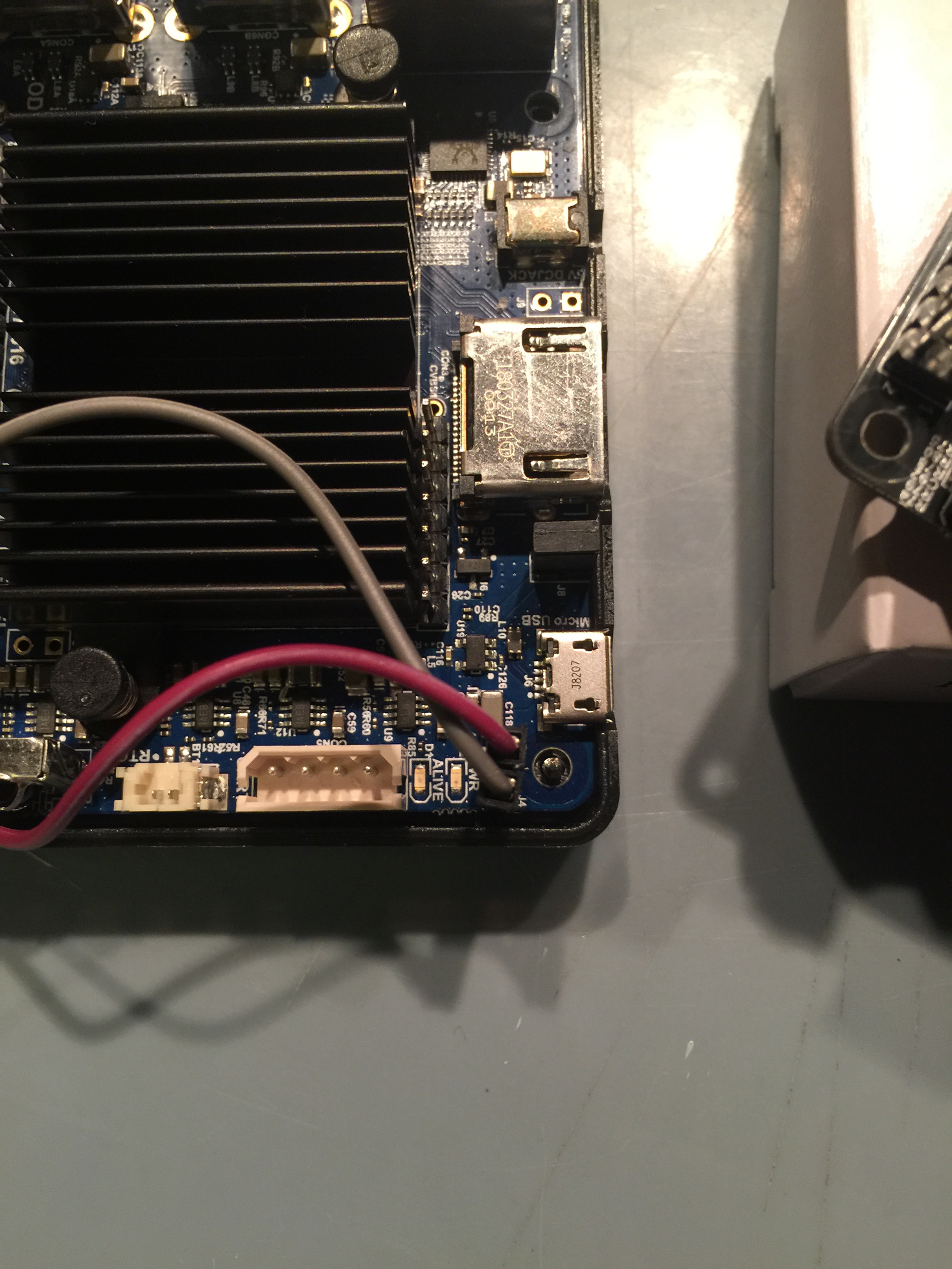
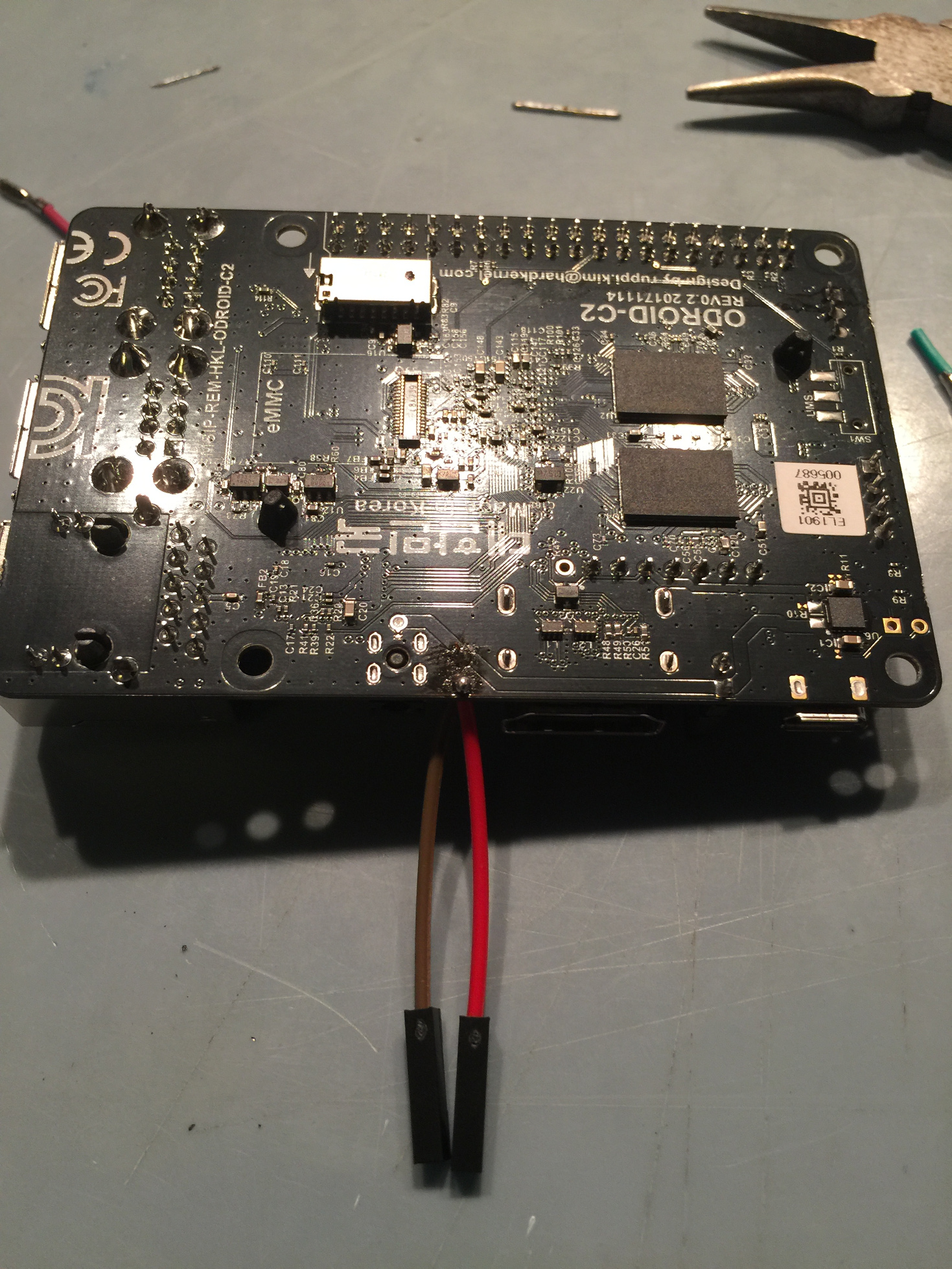
The next step is to solder the board. Turn your soldering iron heat up to 450 or so. Secure the board to your work surface, make sure you have it steady such that it won't move when the soldering iron touches it. I normally would use pins from the ODROID-GO expansion clip but not everyone has one lying around so instead of plugging jumpers into the pins we'll solder the jumper to the board and plug into the other side of them.
Strip and twist the wires like we did for the buttons. Start with the hole furthest away on the board, push the wire through and solder it on, little bit of solder, little bit of time. Repeat for the hole closer to the edge. At this point, you should have something like pictured below. For the C1+ this connection - near the corner of the board - is a bit tight, just be careful, take your time.
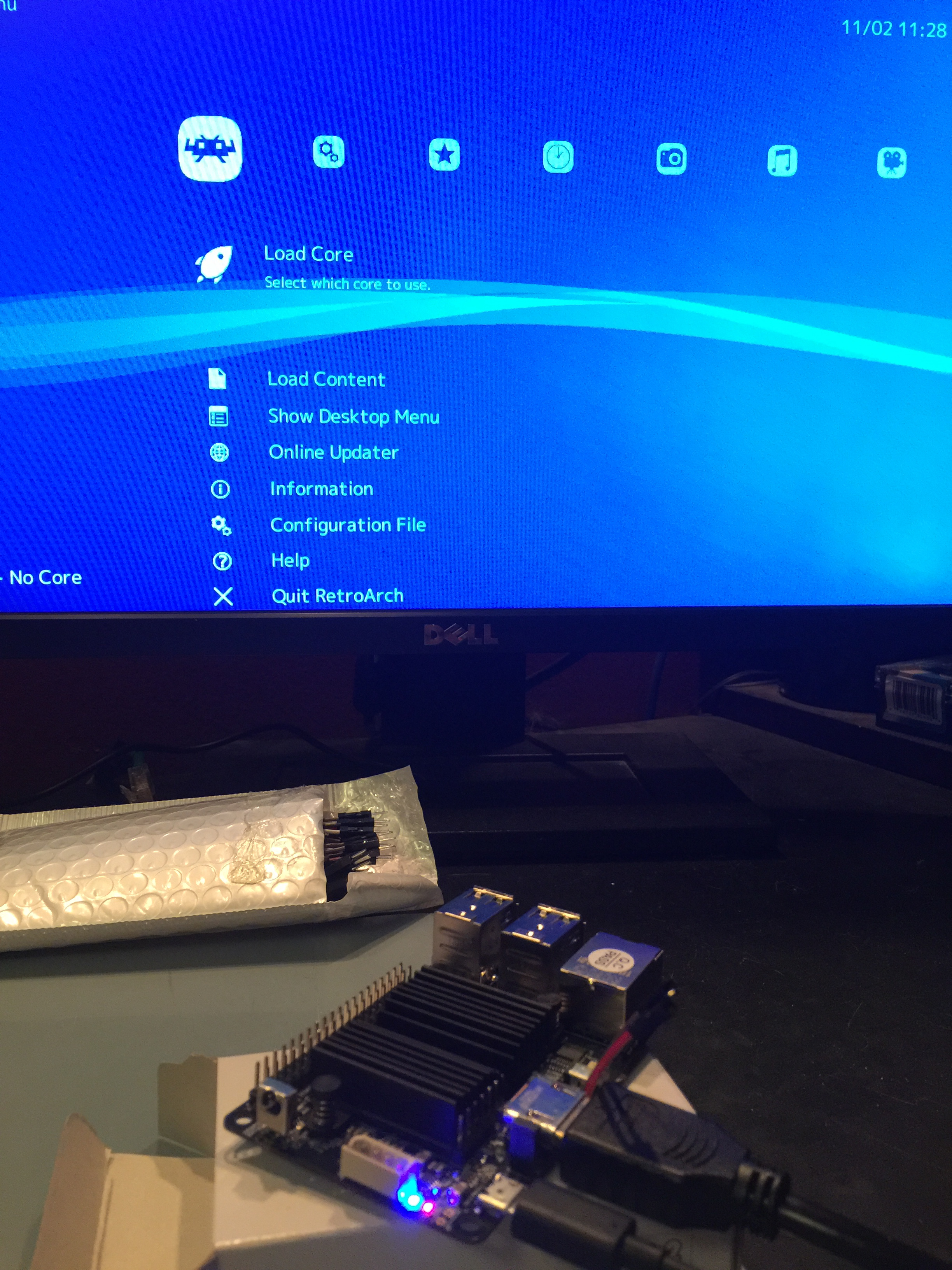
Congratulations, we are done soldering. Let’s test it. Plug in one of your working buttons. Power up the unit without an SD card. You should be able to get the red LED to toggle just like before.
If you have a working C1+ / C2 SD card now is a good time to test and see that everything is working fine. Looking good. If you do not have an SD card, no worries, we'll be at the software step soon. The only thing left on this side of things is the case holes and mounting the buttons.
In the next installment of this tutorial, we will look at building a case for the console.
References http://middlemind.com/tutorials/odroid_go/mr1_build.html
Be the first to comment