

This article will show, in detail, how we build a Monku1000 from a standard ODROID-GO kit from Hardkernel.com. You won't need anything more than a screwdriver set to accomplish this task and we'll show you all the little tips we've learned while building a bunch of these things. This tutorial is driven by photos of each step of the construction, so let's get to it!
Tools Needed
- A small screwdriver set containing a few small Phillips head screwdrivers. - A clean, static-free work surface. - An 8GB or 16GB micro SD card (required for software setup). - Laptop or desktop computer with SD card reader (required for software setup).
The Kit
First things first, let's go over where you can acquire an ODROID-GO. You could search eBay and find a pre-built one, but what would be the fun in that? So your two options are going to be ordering directly from the manufacturer, or ordering from Amazon. Direct ordering is cheaper--the kit goes for $38 USD--but the delivery charges can be a lot. Don't go by the initial delivery cost; enter in some address information to get a more accurate price. It helps to find some friends who also want to build one and go in together to save on shipping. If you order on Amazon.com you will pay around $60 USD for the kit, which comes out to around the same price when you include shipping. I ordered directly from hardkernel.com along with a few other items to make the shipping cost hurt less.
[One of the best domestic sources for purchasing ODROID-GO kits and ALL things ODROID is AmeriDroid at ameridroid.com. -ed]
The Build
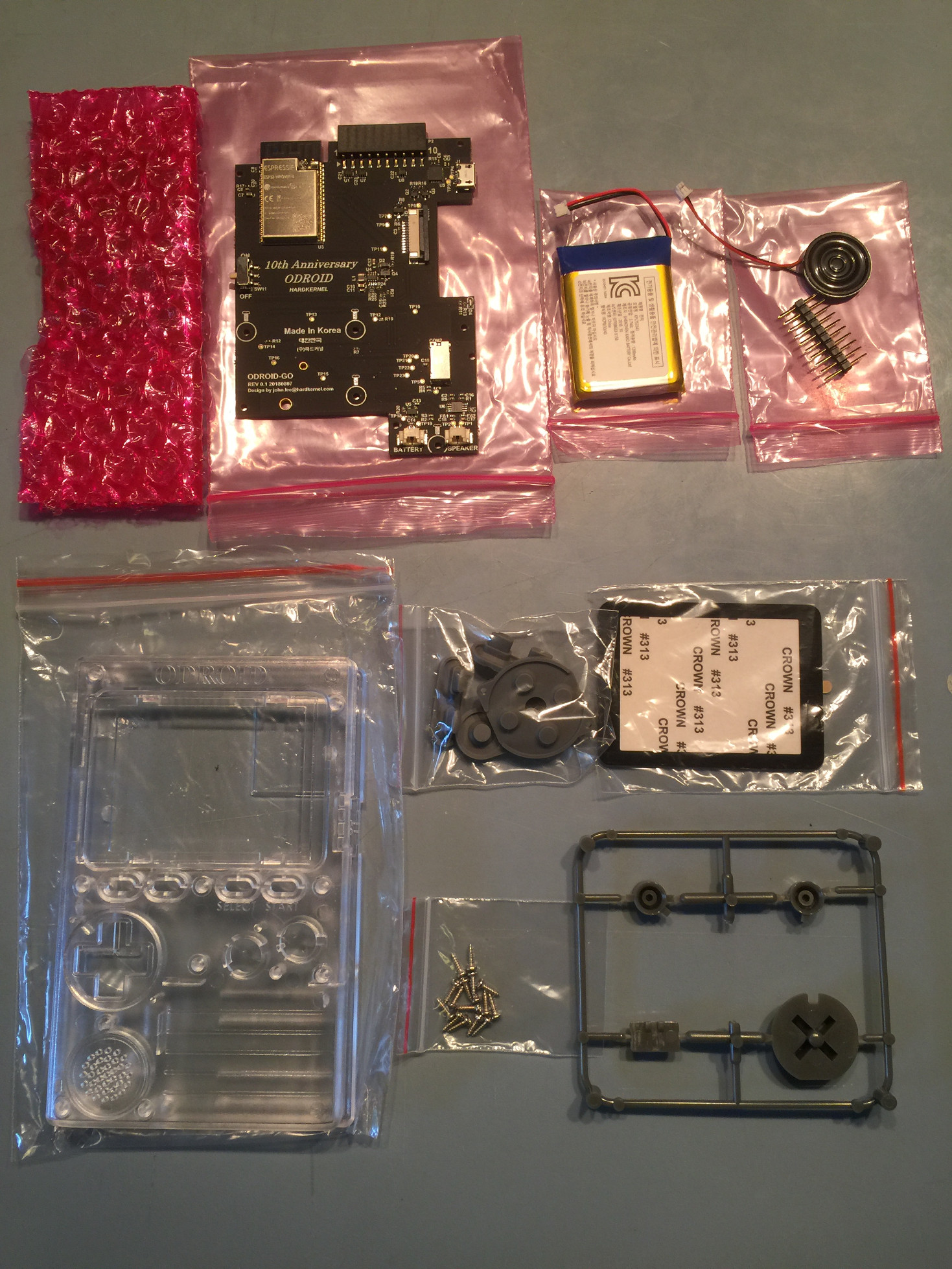
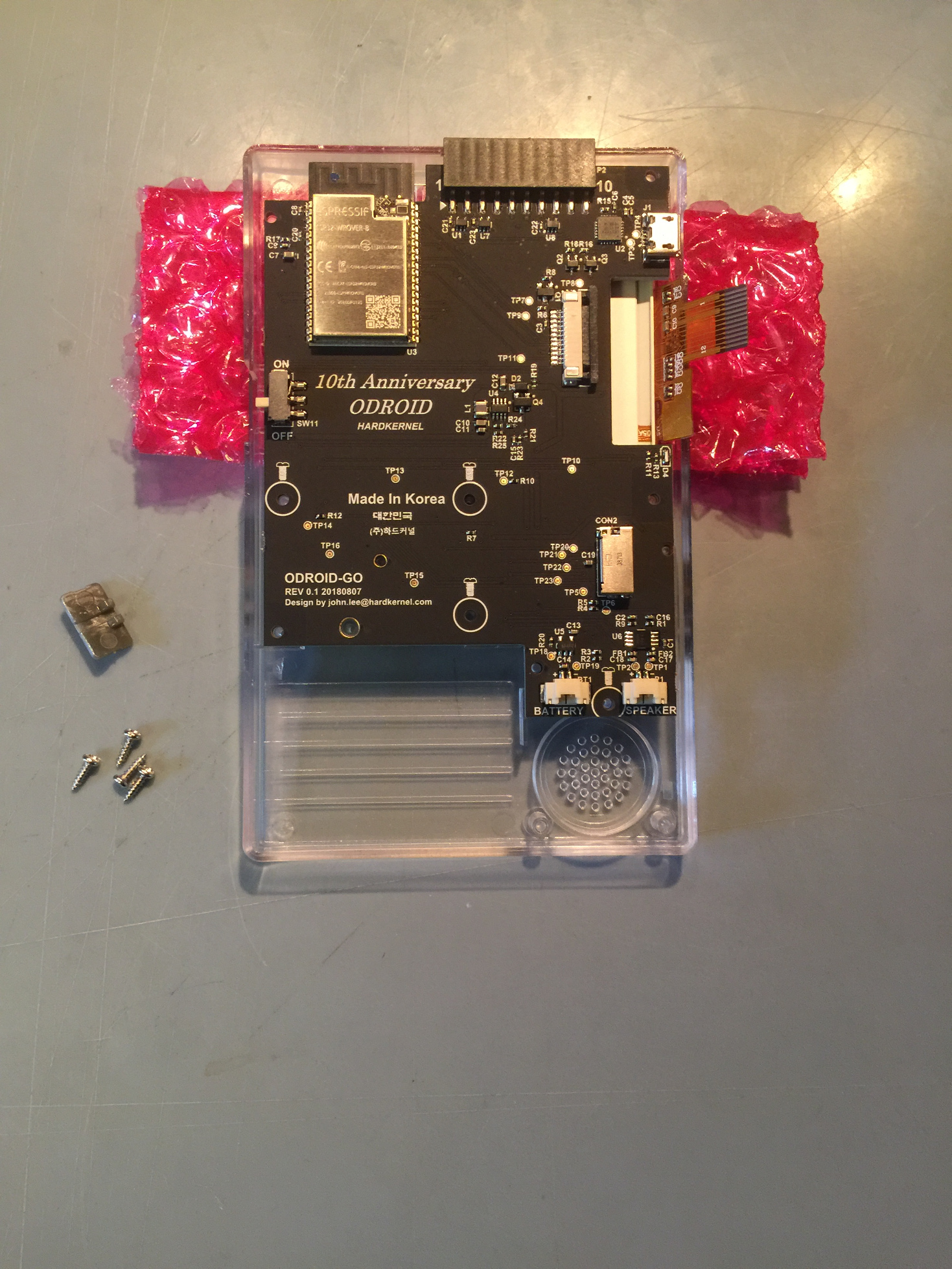
Now that we’ve got that covered, let's start by unpacking the kit and spreading the items out on a clean, flat, static-free work surface. A kitchen table should suffice, but make sure you are in a place where you don't build up a static charge since you can really fry a component with a static shock. Make sure the speaker is away from any metal. The speaker has a magnet and can get damaged if it pulls itself into a sharp metal object.
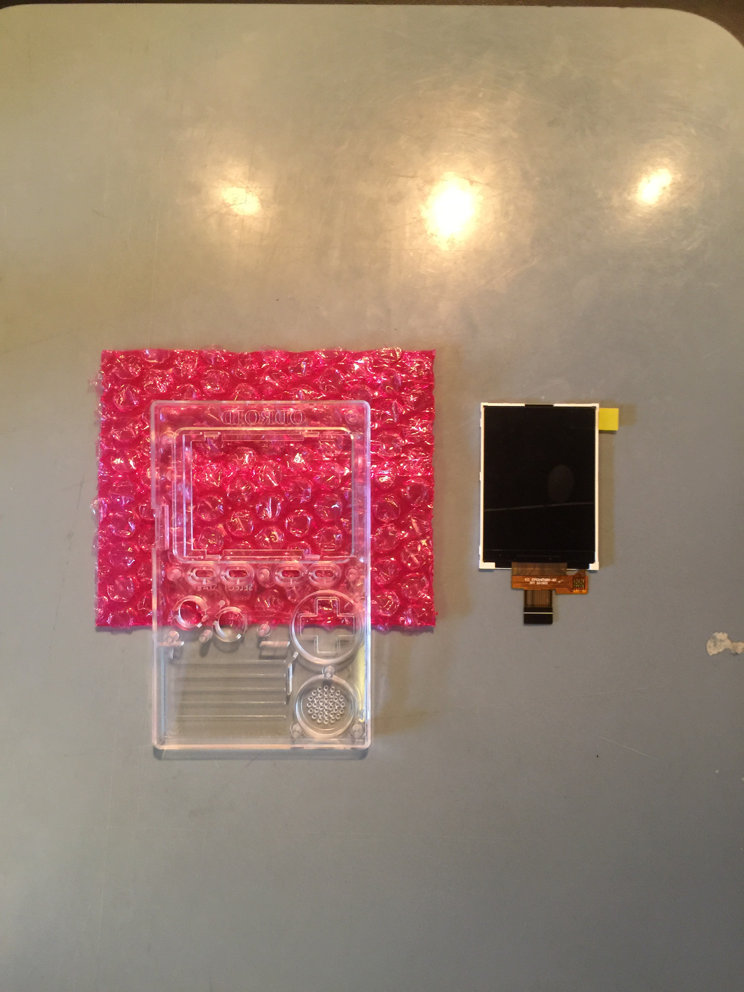
First thing we need to do is take out the case front and screen. Place them on a clear work area. Use the plastic bubble wrap that is protecting the screen as a safe area to place the screen face down. Place the case front face down on the safe area. Using the tab, gently peel the protective layer off the screen. Save this for later use by placing it sticky side up on a clean, out of the way surface.
Next, place the screen face down, inserting the the top of the screen under the plastic tabs at the top of the case's screen hole. Let the bottom of the screen rest on the bottom tabs as shown below.
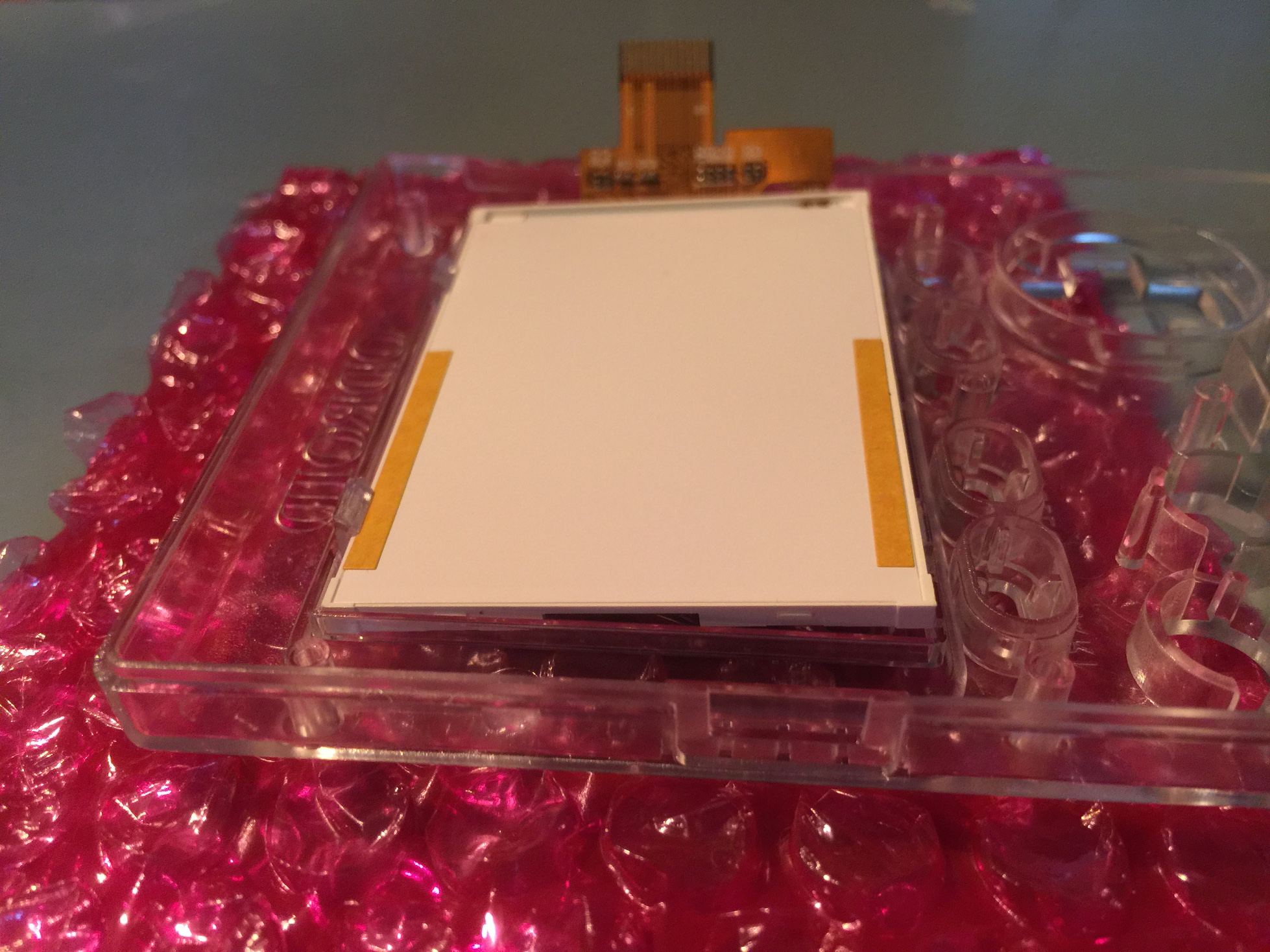
Place two fingers on the bottom of the screen, outside of the tabs, and gently push down until the screen snaps into place. Now grab the protective sticker you peeled off, make sure it is free of debris, and place it on the screen as best you can, protecting as much area as possible.
Fold the pink bubble wrap, and place the case on top of it so the button slots are off the work surface. Now pop out all the buttons from the plastic mold and dump the plastic baggie with the button pads. Place the control buttons on the left and right under the screen. You should have enough room below the case to push the buttons through and have them sit there nicely.
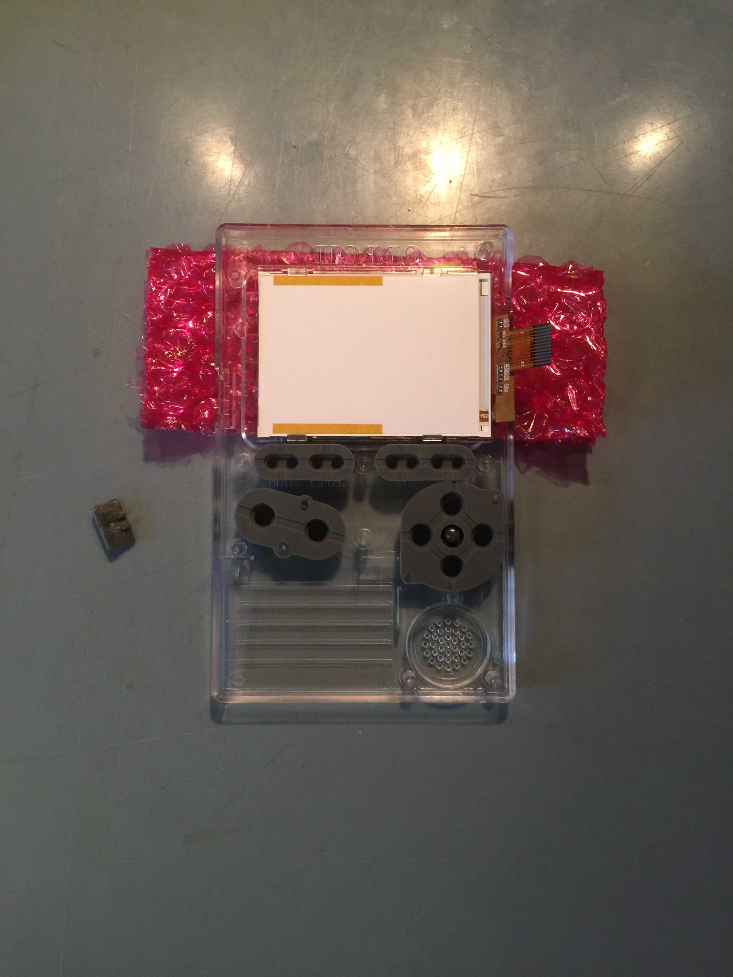
Place the control buttons on the left and right under the screen. Push them down and roll your thumb around to make sure they go all the way in. Place the buttons and the directional joystick in their respective places. Then place the rubber pads on top of each control element. Gently and carefully push down the rubber around the plastic pins just a little bit for each pad.
Place the circuit board in top of the button pads as shown below. The big silver chip should be in the top left corner. The board will line up perfectly with some guide pins.
Hand tighten all four screws while the screen is on the work surface. Then pick up the case and finish them up. You want to tighten them just until they start to get tight. Don't over do it, but they shouldn't be loose in any way--they should be solidly affixed.
Pinch the side of the screen connector, both sides at the same time to close it. You'll want to pull the connection slot all the way out then slide the screen ribbon cable all the way into the connector. Hold the ribbon in while you pinch both the left and right side of the connection slot.
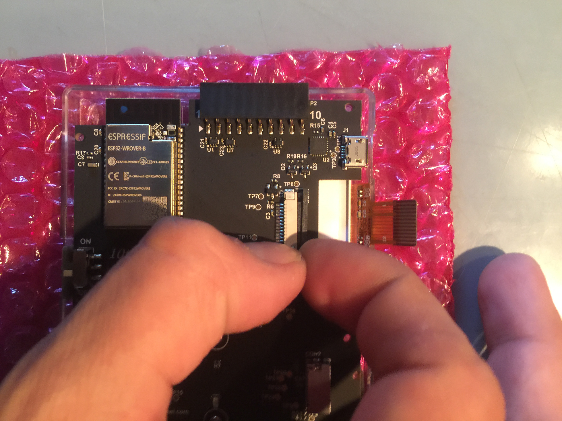
The white line of the screen ribbon cable should be straight and parallel to the line on the circuit board. The white line should be close but not on top of the circuit board line.
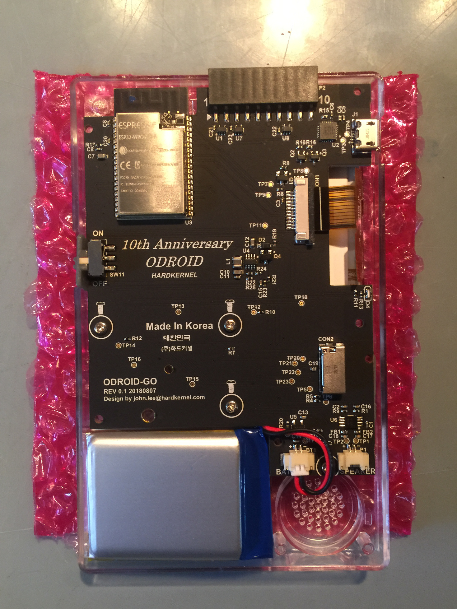
Now is a good time to check the screen. You can quickly plug the battery into the battery connector. Make sure the power switch plastic is in place and turn on the device. You should see an SD card error icon on the screen if everything is ok.
![]()
If you want to customize your device, now is the time you can place a special image in the space where the battery goes. Use the battery for measuring and cutting this addition to the proper size. Wrap the battery cable up on the right hand side of the connector and place as shown below. Slide the battery in from left to right. Bend the battery cables up slightly, and slide the battery into its slot from left to right, then push the left side down until it's snuggly in its place.
Next up is the speaker. Connect the speaker cables and wind up the cable just a bit as shown below. If there is some over hanging plastic on the battery you can slide the speaker cables under the plastic slightly. Make sure the speaker cables are clear of the screw post, and the center of the speaker itself.
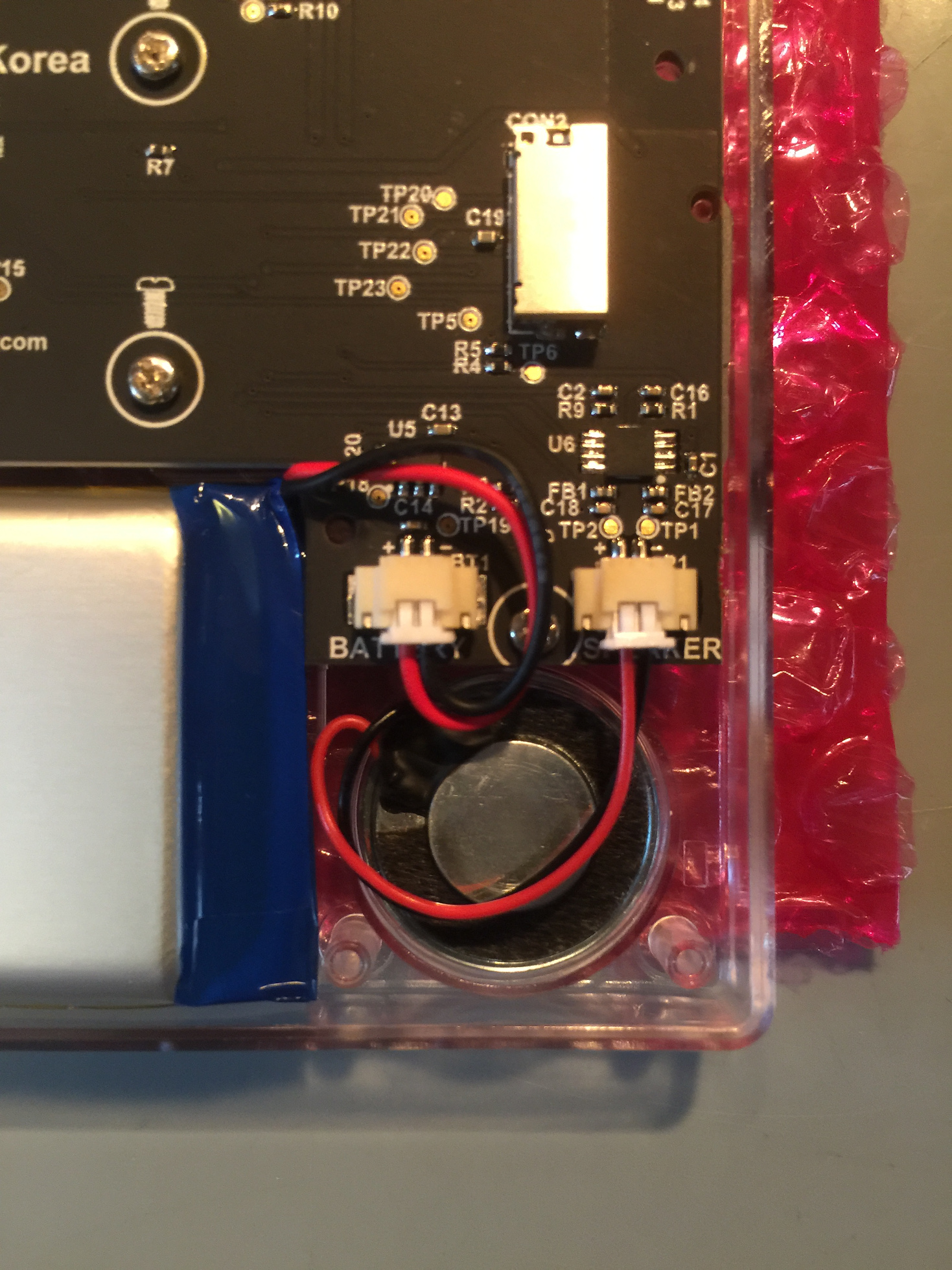
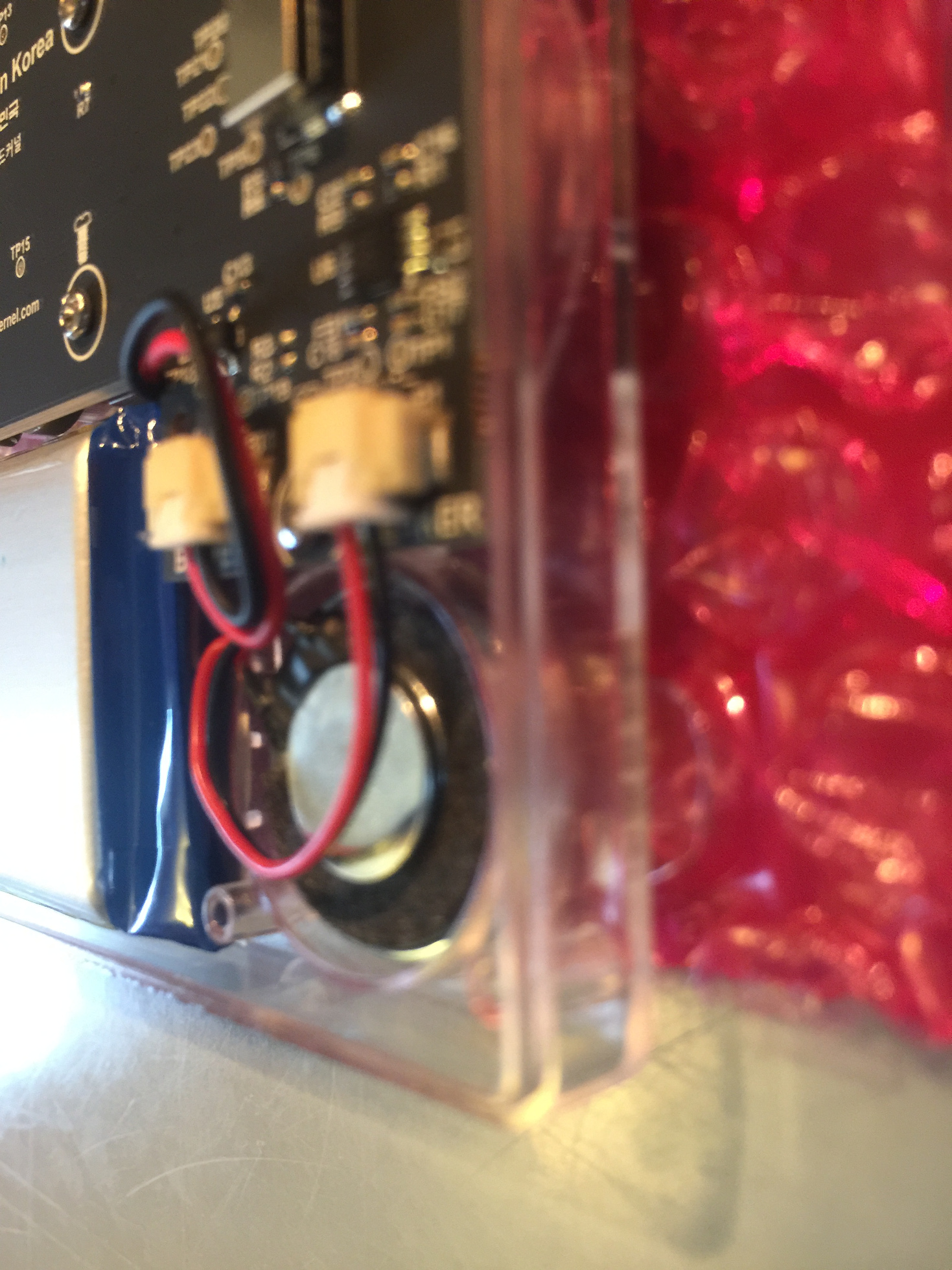
Make sure that the back of the case can cleanly access the screw post and that the speaker holder doesn't pin down the speaker cables. The cables should be clear of the center of the speaker. Close the case with the provided screws. If the bottom right corner by the speaker doesn't close all the way, give the screws near it a few extra turns until it's super tight. You can always remove play in the case from the speaker side but you can't remove play in the case from the battery side because there are no screw posts there. If you do have a lot of play in the case on that side some plastic model cement along the case edge might do the trick. Personally, I just live with it.
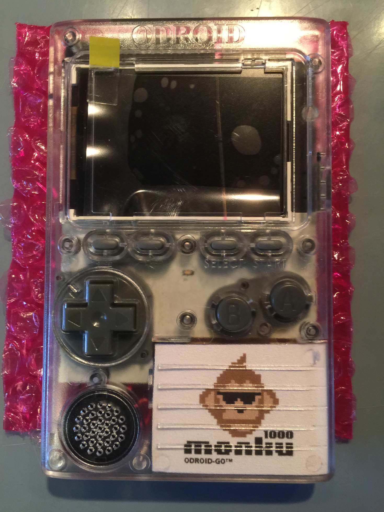
Bam! Now you have a snazzy looking device. The last build step is to add the screen shield. If you haven’t already, remove the protective sticker from the screen.
Peel out the center of the screen shield's adhesive strip. Use your thumb or the end of a screwdriver to keep the edge of the strip down while you peel out the center.
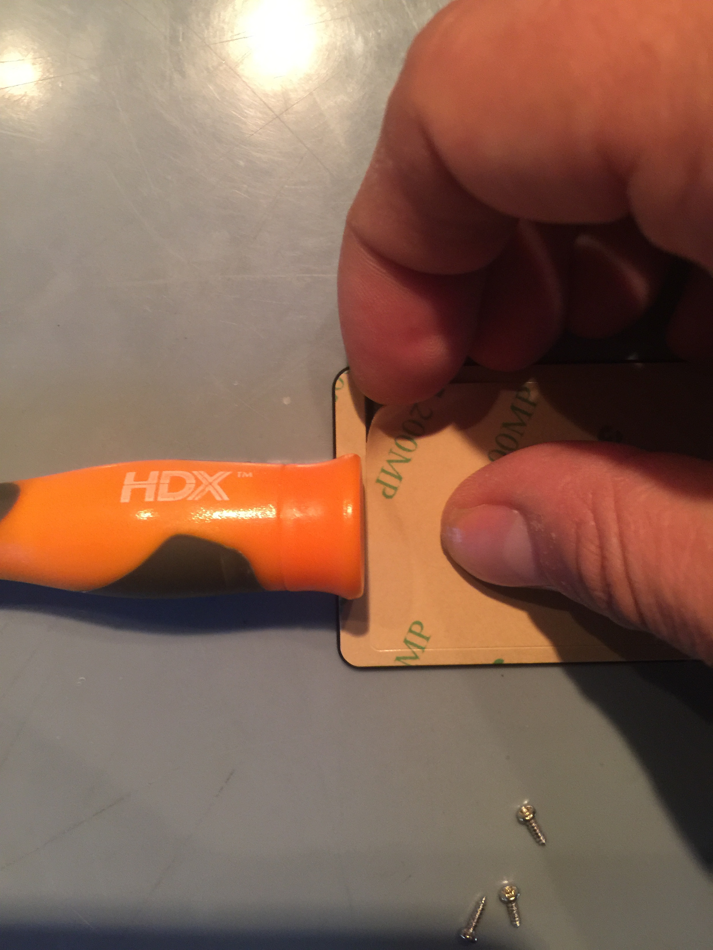
Rip the remaining strip down by the tab then slowly peel it off by going around the plastic shield. Slip the plastic shield into the top of the screen bevel with some downward pressure on the center of the plastic shield.
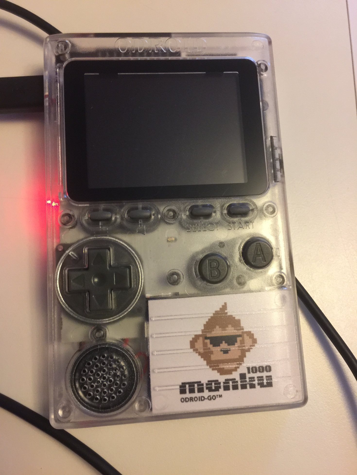
Run your finger around the edge of the screen shield and place the device down on the safe area. Place something on top of it like a phone and let it sit for a few minutes.
Charge your device over USB. The red light will remain on during charging. To see if it has fully charged, plug it back in and see if the red light turns on again. If not then, it's fully charged.
The Software
Check here for info on flashing your device with the latest firmware. You'll need to get the latest version to make sure that things run nicely and and so you can load the go-play emulators (NES, SMS, GG, GB, GBC, CV) when you turn on your device.
For bare bones SD card templates that have everything but the game ROMs also check here. You can grab one of these and copy your ROMs to start gaming right away. You can also find SD card images on eBay for this device--just search for it. Then you'll be all setup to retro game on the go!!
Be the first to comment