

Ever since I started working with Home Assistant and automating various things around the house I wanted to have a way to control the lights. I looked at smart light bulbs, like Philips Hue, but they are expensive (about 12$/bulb - https://goo.gl/xiAqEe). Also, most solutions use proprietary protocols or cloud services which may leak personal data, or might stop working in the future leaving you with expensive paperweights. By accident, I heard about Sonoff wifi switches built by Itead (http://sonoff.itead.cc/en/products/sonoff/sonoff-basic). They combine an ESP8266 wifi-enabled microcontroller and a relay and let you turn things on and off from a distance. Apart from a low price (~5$ - https://goo.gl/WP31Ny), the microcontroller also exposes a few GPIOs and can be flashed with open source software to customize it.
So, the plan was to get several Sonoff Basic switches, remove the case, flash Tasmota firmware (https://github.com/arendst/Sonoff-Tasmota/wiki) and find a way to interface it with my existing light switches. Itead also makes a wifi light switch I could have used (http://sonoff.itead.cc/en/products/residential/sonoff-touch), but is more expensive and I wanted to keep my existing switches. Thankfully I found this youtube guide with an idea on how to convert a basic switch in a light switch: https://www.youtube.com/watch?v=ab472a40-co. You basically need to power the Sonoff, connect its output to the light bulb/light circuit and connect the light switch to GPIO14 and GND pads, and you are in business.
Flashing Tasmota
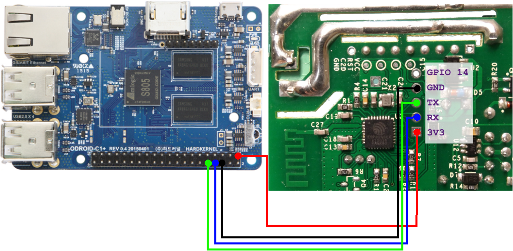
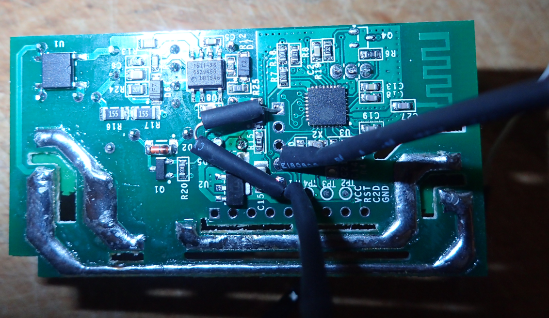
First thing you need to do is to open the Sonoff switch case (it is held in place by a few plastic clips) and identify the GPIO pads (see Figure 1). There you have a 3.3V square pad, UART RX and TX, the ground and the last one is GPIO14. In order to flash a new firmware you need to power the Sonoff, connect the UART to a device running Arduino and hold the button (GPIO0) while it boots to put it into programming mode. In order to do this, you can either solder a 5 pin header to the board or simply position the header so that it touches the pads while you flash (this is what I did). Note that during this operation the Sonoff will not be connected to the mains and will draw power from the UART cable! (details: https://goo.gl/5TUfz8). If you do not have a suitable USB-UART adapter around, you can use the UART pins from the 40 pin header on an ODROID-C1/C2 directly with jumper cables (see figure 1). Make sure to connect RX and TX crossed over so that RX on Odroid is connected to TX on Sonoff. Also, power must come from the 3.3V pin, not the 5V pin.
Software-wise you will need to download and install Arduino IDE (I used Ver. 1.8.5) and some support libraries, which come with the armhf Java program (https://github.com/arendst/Sonoff-Tasmota/wiki/Arduino-IDE). You can download the IDE for armhf from this link: https://goo.gl/ZFYj8Z.
If you are using the ODROID-C2/N1, the arduino program will fail to run because it cannot find relevant 32bit libraries. You will need to install 32bit support in your ubuntu and then run the same steps as for ODROID-C1:
$ sudo dpkg --add-architecture armhf
$ sudo apt-get update
$ sudo apt-get install libc6:armhf libx11-6:armhf libxext6:armhf \
libxrender1:armhf libxtst6:armhf libxi6:armhf
If you are using ODROID-XU4/N1, the steps are the same as above, but you will need to use a shifter shield to address the voltage difference between the ODROID and the ESP chip. For the C1 follow these steps:
$ unxz arduino-1.8.5-linuxarm.tar.xz
$ tar xvf arduino-1.8.5-linuxarm.tar
$ cd arduino-1.8.5
$ ./arduino
Allow it to start, then open Arduino IDE and select File -> Preferences and add the following text for field Additional Boards Manager URLs: https://goo.gl/EVq7nf and select OK. Next, open Tools -> Boards ... -> Boards Manager ... and scroll down and click on esp8266 by ESP8266 Community. Click the Install button to download and install the latest ESP8266 board software. Select Close. You can now close Arduino. In the following step you will download and install Tasmota firmware. You can get the latest version from here: https://github.com/arendst/Sonoff-Tasmota/releases
$ cd ..
$ wget https://goo.gl/KQwDvr
$ tar zxvf v5.13.1.tar.gz
$ cp -ar Sonoff-Tasmota-5.13.1/lib/* arduino-1.8.5/libraries/
$ cp -ar Sonoff-Tasmota-5.13.1/sonoff/ arduino-1.8.5/
$ cd arduino-1.8.5
$ ./arduino
You can now open the Tasmota project by selecting File -> Open and locating and loading sonoff.ino from the sonoff directory under arduino-1.8.5. In the list of open tabs locate user_config.h, where you need to change the following settings. Note that changing settings here is not mandatory - most of them can be configured later through the web interface or MQTT, but once you reset to hardware defaults, these will be those defaults:
- Set static IP address if desired (WIFI_IP_ADDRESS, WIFI_GATEWAY, WIFI_SUBNETMASK, WIFI_DNS)
- Set SSID/Password for two access points (STA_SSID1, STA_PASS1, etc)
- Set configuration tool to WIFI_RETRY (WIFI_CONFIG_TOOL), so that if it cannot connect to WiFi it will keep trying instead of becoming an access point. Otherwise some attacker could knock it off the WiFi network with a deauth attack (see https://goo.gl/76kYPs) and force it to become an access point and re-configure it.
- Enable syslog if you have one (it helps debugging issues, though local logs will be preserved on the device, accessible through the web interface until reboot)
- Disable (comment with //) MQTT TLS (//#define USE_MQTT_TLS)
- Set MQTT broker IP, user, password (MQTT_HOST, MQTT_USER, MQTT_PASS)
- Disable MQTT Retain (caused me some headaches) (MQTT_BUTTON_RETAIN, MQTT_POWER_RETAIN, MQTT_SWITCH_RETAIN)
- Define a topic for MQTT messages (MQTT_TOPIC). Something like kids_light, or bedroom_light for example
- Disable Domoticz if not needed (//#define USE_DOMOTICZ)
- Set up a username and password for the web interface for a bit of protection (WEB_USERNAME, WEB_PASSWORD)
- Disable mDNS discovery (//#define USE_DISCOVERY)
- Set up NTP servers (NTP_SERVER1, etc)
- Set up timezone (APP_TIMEZONE)
- Disable I2C if not used (//#define USE_I2C)
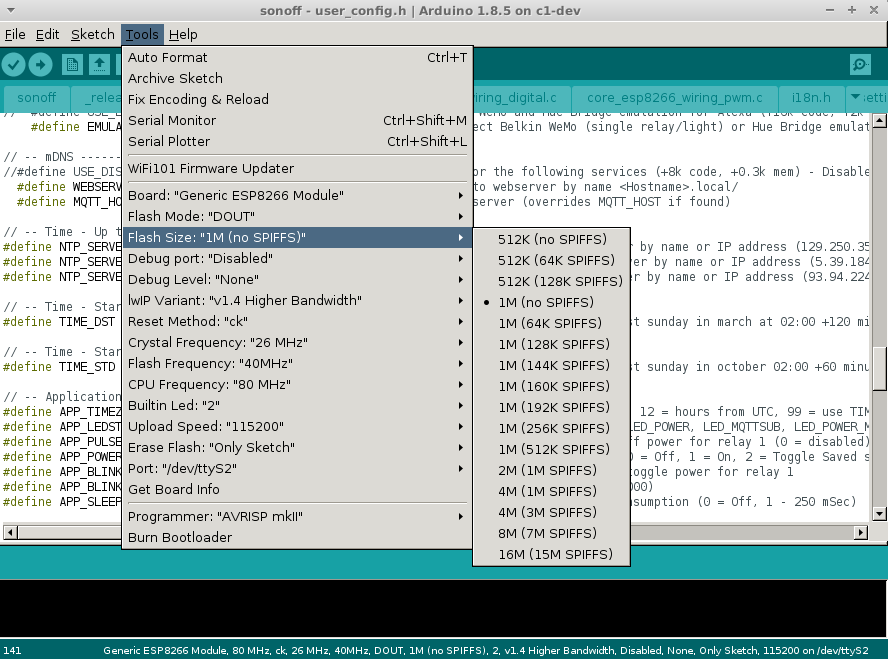
Once your configuration is complete, you need to define flashing mode by making the changes defined here: https://goo.gl/NmnZBE in Arduino IDE. You will need to select /dev/ttyS2 as a port with 115200 baud-rate.
When done, insert the pin header in the Sonoff while holding the power button pressed and release the button when it has a steady connection. Start compile and flash (the second button with an arrow symbol in Arduino IDE) and wait for it to complete. If flashing fails, try again to put the Sonoff in programming mode and try again. After flashing is done, power up the Sonoff and it should connect to your desired WiFi. You can power it through the makeshift UART cable, or from the mains - but make sure to reassemble it if using the mains so that you do not risk getting shocked. You can find out its IP address (either static, or from DHCP) by consulting your router's client list. You can then connect via HTTP to its management address to configure it further.
Tasmota configuration
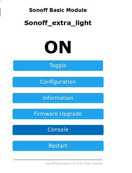
Tasmota firmware is mostly built with MQTT in mind. MQTT is a machine to machine messaging protocol that we have discussed in a previous article (https://goo.gl/9ggqHJ). It allows integration of multiple entities with a message broker (we are using mosquitto), and also is well supported by Home Assistant. Tasmota firmware has many parameters you can configure via MQTT or REST API, (complete list here: https://github.com/arendst/Sonoff-Tasmota/wiki/Commands), but the most important ones can be configured via the web interface.
We will be configuring the following:
- GPIO14 will have the same role as Switch1. To do this, you can navigate to the web interface, inside Configuration -> Configure Module: Module Type: 01 Sonoff basic GPIO14 sensor: 09 Switch1
- If you have not configured MQTT in user_config.h yet, you can do so now by going into Configuration -> Configure MQTT and add the broker address and username/password.
If you are using passwords with MQTT, you will need to add the new account in mosquitto:
$ sudo mosquitto_passwd /etc/mosquitto/passwd sonoffuserIf you wait a second the Sonoff should connect to the MQTT broker and you should be able to control it from the command line. Assuming you are using a topic of bedroom_light you can turn on the switch with:
$ mosquitto_pub -p 1883 -u sonoffuser -P sonoffpassword \
cmnd/bedroom_light/POWER -m "1"
You can query the device for its settings or information through MQTT, but the replies will be sent to the syslog server so you need to keep an eye on it when issuing MQTT commands. To get the switch state run:
$ mosquitto_pub -p 1883 -u sonoffuser -P sonoffpassword cmnd/bedroom_light/POWER -m ""The corresponding syslog server output would look like so:
May 25 17:43:42 sonoff_bedroom ESP-MQT: stat/bedroom_light/RESULT = {"POWER":"ON"}
May 25 17:43:42 sonoff_bedroom ESP-MQT: stat/bedroom_light/POWER = ON
You can now play with setting parameters which are not available through the web interface, such as PowerOnState (https://goo.gl/hJqRTd):
$ mosquitto_pub -p 1883 -u sonoffuser -P sonoffpassword \
cmnd/bedroom_light/PowerOnState -m "3"
One extra thing you can configure is the ESP power management. It is disabled by default, but you can instruct it to go into 100ms sleeps to reduce power (and heat) with this command:
$ mosquitto_pub -p 1883 -u sonoffuser -P sonoffpassword \
cmnd/bedroom_light/Sleep -m "100"
In order to integrate the Sonoff as a light switch into Home Assistant you can add the following to configuration.yaml and restart:
light:
- platform: mqtt
name: "Bedroom Light"
state_topic: "stat/bedroom_light/RESULT"
value_template: '{{ value_json["POWER"] }}'
command_topic: "cmnd/bedroom_light/POWER"
availability_topic: "tele/bedroom_light/LWT"
qos: 1
payload_on: "ON"
payload_off: "OFF"
payload_available: "Online"
payload_not_available: "Offline"
retain: false
…
group:
lights:
name: Lights
view: yes
icon: mdi:lightbulb-on-outline
entities:
- light.bedroom_light
Make sure the code above uses the correct topics that you set for your device. You can restart Home Assistant and test that everything works as expected (you should be able to toggle the switch from Home Assistant, Tasmota's web interface and the button on the Sonoff).
The hardware build
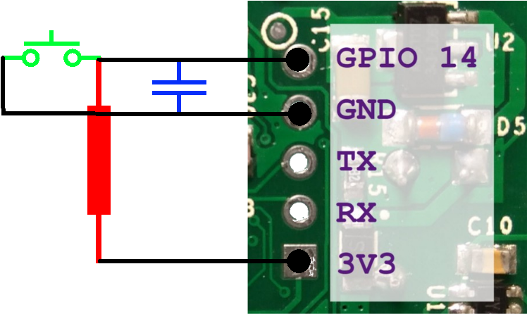
In order to proceed and connect the light switch to GPIO14 we need to do some soldering and add a low-pass filter along with connector cables to GPIO14 and GND. The reason why we need a low-pass filter is because EM radiation will be picked up by the wires used (they act like an antenna) and may cause the switch to randomly toggle at times. To mitigate this you can use a low-pass filter so that only DC is allowed to pass and also you can twist the wires so that the interference cancels out (http://goo.gl/7zEPc9).
You can build a low-pass filter by following this guide (https://www.youtube.com/watch?v=aq8_os6g13s) with a 10k resistor and a 33pF capacitor. Exact values are not that important - you can use whatever you have.
Make sure the soldering is solid and use heat shrink tubing to isolate your components. When you are done test the unit taking care not to touch the exposed AC traces. You should also run some electric tape over it because we will not be using the plastic cover.
Attaching Sonoff to the lights
This step may be the trickiest one, because light wiring may differ from place to place and you may not have everything you need in one place. You may need to consult your electrician, the electrical code and local legislation before you proceed. Most importantly, make sure to turn off the breakers for lights and sockets before dismantling the light switch or you will risk death. You will also need a test light (https://en.m.wikipedia.org/wiki/Test_light) to identify the live wires.
Let us briefly analyze what wires run through your walls to power sockets and lights. You will have a "hot" wire (also known as "live") which has a voltage potential of 110/220V depending on where you live, a "neutral" wire which is used to complete the circuit and offer a path for the current to take (this is usually not energised) and a "ground" wire used in some electrical sockets as an emergency backup path for the neutral wire. In order to power the Sonoff we need a live and a neutral inside the light switch enclosure.
Unfortunately, not all wiring standards provide the neutral wire, so we might need to make one. In my case (and I suspect it is common for most Europe) the light switch has a live input that goes to two mechanical switches and that can continue with two independent live output wires that go up through the wall to my light fixture.

There is no neutral near the light switch. The neutral goes to the light fixture itself and closes the circuit through the lightbulb. Well, that will not do. We need to modify the circuit and suspend one live output and transform it into a neutral with a bit of wiring, mostly because I did not want to run another wire through the wall (difficult without skill/special tools).
The first thing you need to do is cut power to the breakers and remove your light switch from the wall to have a look at the wires. It might be a good idea to test and see if the Sonoff PCB fits inside the light switch electrical box (it will not fit in most Eastern European round electrical boxes). If it does not fit you need to be creative and find a place where to put it.
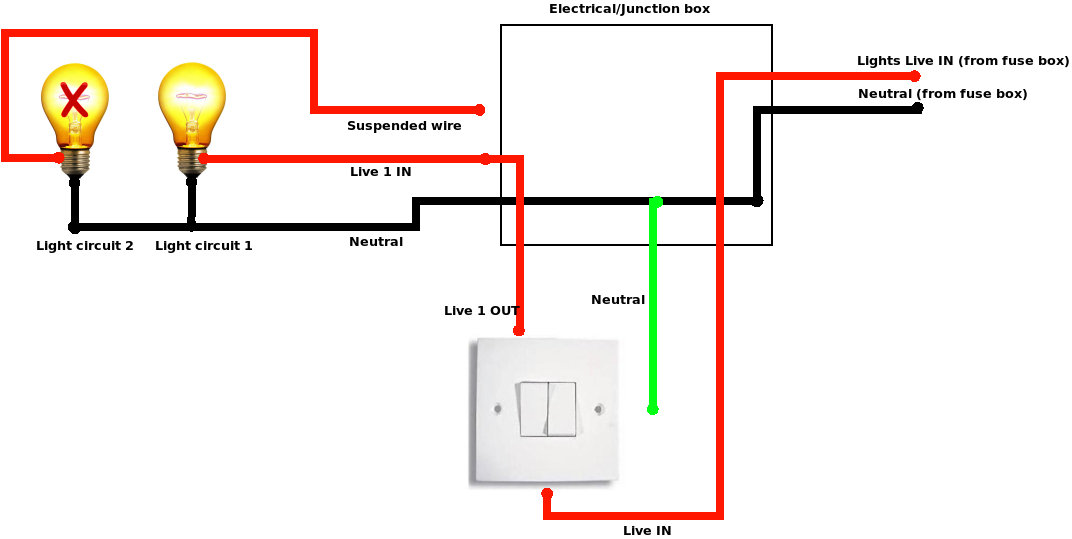
My plan is to convert a live output wire into a neutral input by disconnecting the output wire from the bulb and connecting it to neutral. By doing this I will not be able to use a light fixture with two independent lights, but I have a simple light fixture anyway, so it is no problem. There are two places where you can do this - in the intermediary electrical box (which should be close by, near the ceiling), or at the light fixture. Both wiring diagrams are presented in figure 8 and I will describe the steps needed for each variant.
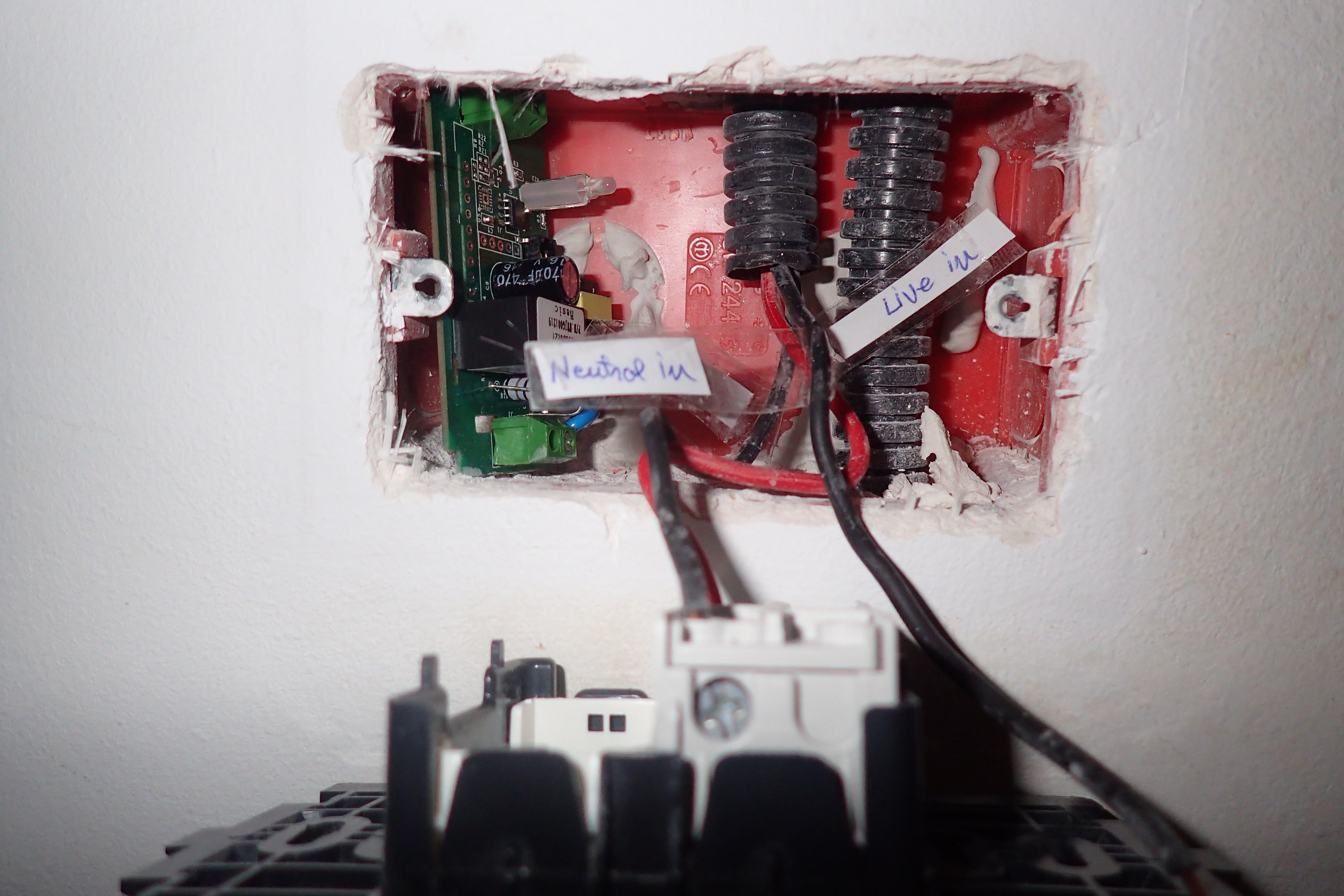
For the 8A option you need to have a look in the connection electrical box. This box should contain all electrical circuits that go to a room - lights and sockets. When you have a look inside (with the breaker off) you will probably see a jumbled mess of wires, like in figure 9. You need to identify (based on color and position) which wires go to your light switch and which go to the light bulb. You also need to chose which live output wire you want to convert to neutral and identify the top end of that wire in the electrical box. You can do this either by pulling on the wire and observing which wire moves, or by measuring the resistance of the wire ends (prolonged if needed) with an ohmmeter (resistance should be close to zero). Make sure to label all the wires you identify for future reference, in case you need to undo this mess later on.

Next you need to identify a neutral wire in the electrical box. You should find two bigger bundles of wires with 3 or more wires connected together. One bundle connects all live wires (the one coming from the breaker with the one going to the light switch and the ones going to the sockets) and the other bundle will hold all the neutrals. You can find which is wich by identifying which is the hot wire going to your light switch, or by measuring them with a tester.
Now (with the breakers off) you need to disconnect the live output from the wire going to the bulb and connect it with the other neutrals. The remaining wire will be unconnected (but it is still a good idea to label and isolate its end).

At this point you can connect the sonoff with live in and neutral in its input and live out in the output (with the breakers still off) and then test your setup.
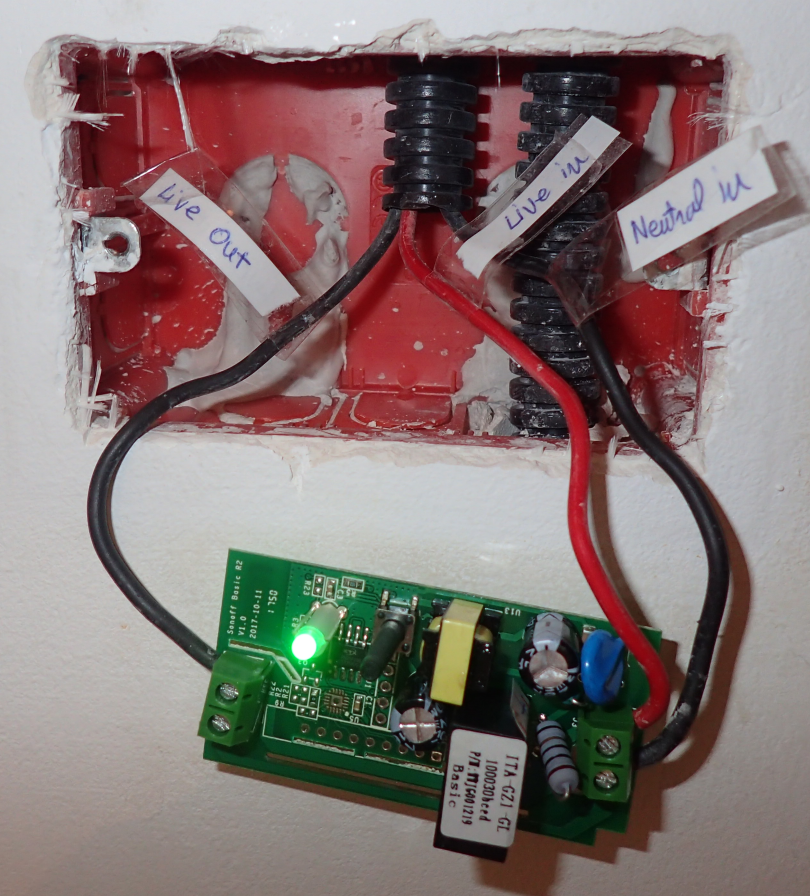
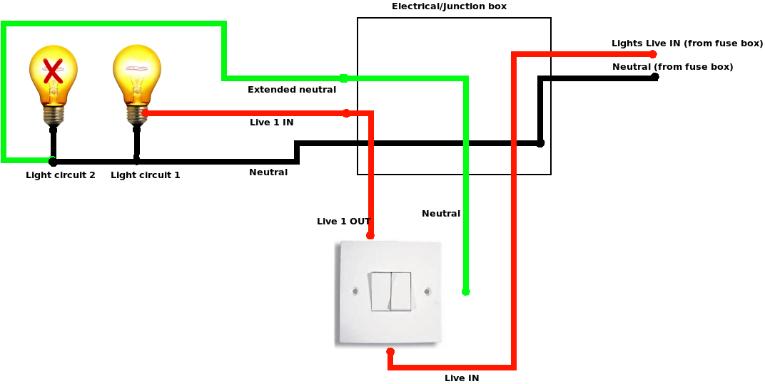
For the 8B option you do not need to make changes in the electrical box. I had to do this because the electrical box in my bedroom is not easily accessible. In this case we bring the neutral from the light fixture back to the light switch by connecting the neutral wire available in the light fixture directly to an old "live in" wire which we will call neutral from now on. Take great care with identifying which is the correct wire, otherwise if you directly connect neutral to the real live wire, you will create a short circuit and your fuse will blow/melt.
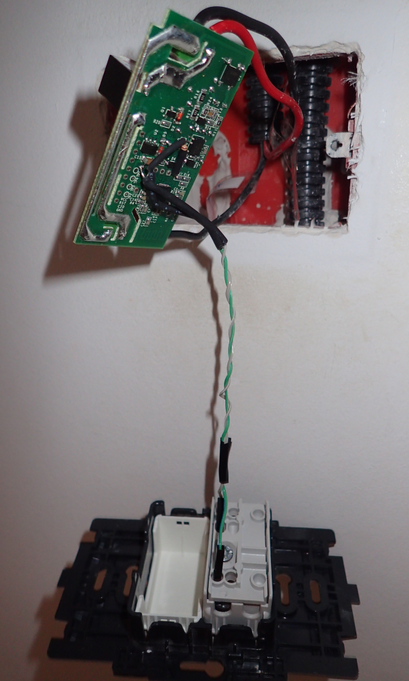
Like in the previous example you will need to connect live in and neutral in to the Sonoff's input and live out to the output (with the breakers off). Connect the lightswitch to GPIO14 and GND as well. After the tests are successful you will need to gently seat the sonoff inside the light switch electrical box and attach the light switch back to the wall and you are done.
Automations
You should now have working light switches in Home Assistant that you can also toggle with the old mechanical switch, but it is not very impressive for the amount of work put in. Why did I want "smart" lights in the first place? Let us see.
Turn off the light after 30 minutes
Sometimes you might forget a light turned on when you leave for work. With network-enabled lights you can turn it off yourself, but that is not automation. In my case, the kids like to fall asleep with the lights on (despite the night light) so we always had to turn it off once they were asleep. If they awoke in the middle of the night they would still turn it on and go back to sleep. So, an elegant way to fix this is to create an automation that between a certain time interval (23:00-17:00) turns off the lights after they have been on for 30 minutes. You need to edit automations.yaml and add the following two automations:
- action:
- data:
entity_id: light.kids_light
service: homeassistant.turn_off
alias: Turn off Kids Light after 30 min inactivity
condition:
- after: '23:00'
before: '17:30'
condition: time
id: '1525335992266'
trigger:
- entity_id: light.kids_light
for:
minutes: 30
platform: state
to: 'on'
- action:
- data:
entity_id: light.kids_light
service: homeassistant.turn_off
alias: Turn off Kids Light at 23:00
condition: []
id: '1525343566208'
trigger:
- at: '23:00'
platform: time
The first automation listens for state changes that happen when the light turns on and if it is in the required time interval waits for 30 minutes to pass before turning it off. The second automation handles the case where light is turned on at 22:00 let us say and the previous automation will not have effect (the state change needs to happen during 23:00-17:00) - so it is lights out at 23:00. You can improve this automation and have it check if somebody is home/in the room, or operate only when the sun is up, etc.
Disable the hardware switch
If you had small children you would have noticed that there is a period in their development when they need to push all the buttons. If they get hold of the light switch they will toggle it on and off till it breaks. To prevent that you can now lock the mechanical light switch so that it will not toggle the light when pressed. Simply set GPIO14 to none in the configuration. You can do this over MQTT and it will cause the sonoff to reboot (light flickers for ~250 ms). You can create the following scripts in Home Assistant, inside scripts.yaml:
'enable_kids_light':
alias: Enable Sonoff Kids Light
sequence:
- service: mqtt.publish
data:
topic: cmnd/kids_light/Gpio14
payload: 9
qos: 1
retain: false
'disable_kids_light':
alias: Disable Sonoff Kids Light
sequence:
- service: mqtt.publish
data:
topic: cmnd/kids_light/Gpio14
payload: 0
qos: 1
When you call the script (either from the Services menu or from a dashboard) the lights will lock or unlock and you can control them only over wifi.
Wakeup call
The last application is more sinister. If you have heavy sleepers in your family that need convincing to be woken up, how about using the US Military Bugle wake up call (https://www.youtube.com/watch?v=xt4hSs4IWPg)? Apart from sound we will also make the light flash with the same pattern as the music. That should be annoying.
You can start by downloading the audio and converting it to mp3:
$ sudo apt-get install youtube-dl ffmpeg
$ youtube-dl -f 140 "https://www.youtube.com/watch?v=xt4hSs4IWPg"
$ ffmpeg -i "US_Military_Bugle_Wake_Up_Call-xt4hSs4IWPg.m4a" \
-acodec libmp3lame -b:a 128k "Wakeup_Trumpet.mp3"
I am using MPD as a media player controlled by Home Assistant, so make sure to move the MP3 file somewhere in MPD's media library path, so it can be played (typically inside /var/lib/mpd/music/). You will also need to add it to a saved playlist (I used "wakeupalarm" as a name).
$ cp Wakeup_Trumpet.mp3 /var/lib/mpd/music/wake-up/Next we need to produce some rhythm information. It should correspond to on and off signals to the light bulb. My idea was to "type" the rhythm on the keyboard as I am listening to sound so that a key press/hold represents light on, a key release represents light off. We can use evtest to select the keyboard and log the duration and sequence of key presses:
$ sleep 10; ffplay Wakeup_Trumpet.mp3
$ sudo evtest 2>&1 | tee trumpet.txt
Once done, the file should contain lines like the following, recording key up/down events for the letter "A":
Event: time 1525422859.108421, -------------- SYN_REPORT ------------
Event: time 1525422859.204406, type 4 (EV_MSC), code 4 (MSC_SCAN), value 70004
Event: time 1525422859.204406, type 1 (EV_KEY), code 30 (KEY_A), value 1
Event: time 1525422859.204406, -------------- SYN_REPORT ------------
Event: time 1525422859.300420, type 4 (EV_MSC), code 4 (MSC_SCAN), value 70004
Event: time 1525422859.300420, type 1 (EV_KEY), code 30 (KEY_A), value 0
The file trumpet.txt will be your rhythm file and needs to be copied to /home/homeassistant/.homeassistant/. You can also get my interpretation of it from here: https://goo.gl/cFpLbs.
$ sudo cp trumpet.txt /home/homeassistant/.homeassistant/Now we can build an appdaemon app (described in this previous article: https://goo.gl/npGqoX) that when triggered by an input boolean, instructs MPD to start playing the trumpet and parses the rhythm text file and issues the corresponding on/off commands to the light. You can get the app and its configuration from here (built for appdaemon 3.x): https://goo.gl/Kn7PLK.
$ cd /home/homeassistant/.homeassistant/apps
$ wget -O sound_and_light_alarm.py https://goo.gl/aNuUB6
Adjust the following configuration to match your environment (changes done in apps/sound_and_light_alarm.yaml):
sound_and_light_alarm:
module: sound_and_light_alarm
class: SoundAndLightAlarm
media_player: "media_player.mpd_kids"
light: "light.kids_light"
music: "wakeupalarm"
rhythm: "/home/homeassistant/.homeassistant/trumpet.txt"
trigger: "input_boolean.wake_up"
You can add the following boolean to Home Assistant (configuration.yaml):
input_boolean:
wake_up:
name: Wake up
initial: off
And the following automation will trigger it when you need to - for example during weekdays, at 7:00 (automations.yaml):
- id: '1527938039163'
alias: Wake up alarm
trigger:
- at: 07:00
platform: time
condition:
condition: time
weekday:
- mon
- tue
- wed
- thu
- fri
action:
- data:
entity_id: input_boolean.wakeup
service: input_boolean.turn_on
You can see it in action here: https://www.youtube.com/watch?v=ac9xnA6Y918. From the outside it looks like your house is trying to communicate via morse code with an alien mothership, but hopefully it will get the heavy sleepers up and running.
Troubleshooting
If you find yourself that lights turn off (or on) apparently at random there may be several things going on. In my case my lights would sometimes lose TCP connectivity to the MQTT server and would reestablish a new connection. Once the connection was up it would read the state from the MQTT server and would override the local state. If you are using the "retain" option inconsistently, this leads to problems such as an open light would turn off after a reconnection. In this cases it is best to disable MQTT retention and rely on local state of the switch. This means that if the light is on and there is a power outage, the light will come on when the outage is restored and you will not be able to force it off through MQTT while the light is unpowered. More details can be found at: https://goo.gl/ECUqRY.
One more problem you might face is that when you restart Home Assistant your light entities default to "off", even if a light is on. In order to fix this you can instruct Home Assistant to "ask" all the lights what their state is with the following automation (add to automations.yaml):
- action:
- data:
topic: cmnd/sonoffs/POWER
service: mqtt.publish
alias: Get Sonoff states on restart
condition: []
id: '1518951376931'
trigger:
- event: start
platform: homeassistant
Hopefully this article helps you implement a smart light system without too much cost or vendor lock-in.
Be the first to comment