
")
Using an ODROID-GO handheld gaming system for controlling a couple of small DC motors that are housed inside a treaded tank robot is easier than you may think. This chore is even more remarkable when you learn that only two of the GO’s general purpose input/output (GPIO) pins are used for this task.
Generally speaking, a “typical” control interface for a DC motor consists of five separate and independent lines: the obvious power/control lines, such as 5V or GND, and three logic inputs from a robot controller (e.g., an input for forward, one input for backward movement, and a final logic line for controlling the motor’s speed). Sharp-eyed readers, however, will notice that only two lines actually connect to the motor. Those other three lines configure a motor controller for “driving” these two connected power lines (i.e., change polarity and drive a series of pulses to the motor via a pulse width modulated (PWM) signal). How is this possible?
The “secret sauce” for this whole operation is a small circuit that resides between the robot controller and the DC motor. This circuit can be variously referred to as a “motor driver,” “H-Bridge,” or “motor controller,” but its function is to operate the motor in accordance with the commands sent from the robot controller.
In our case, the ODROID-GO is the robot’s controller. A Devastator Tank Mobile Platform from DFRobot is our treaded tank bot. A small transistor switch circuit is our motor driver, this is NOT an H-Bridge circuit, however, it’s a simple power switch. Furthermore, only two GPIO pins will be used for driving our tank bot: GPIO #4 and GPIO #15. We will, however, also need to use the GND pin #1 and the 3.3V pin #6 from the ODROID-GO GPIO header interface. These power pins DO NOT drive the robot. Rather, these pins are used for helping the ODROID-GO “talk” with our transistor-based motor driver circuit.
And the best part of GO-Tank is that your WiFi-enabled smart device will be used for steering the tank bot.
Parts
- DFRobot Devastator Tank Mobile Platform #ROB0128 $84.90 (mouser.com)
- Hardkernel Level Shifter: 5V to 3.3V $1 (hardkernel.com or ameridroid.com)
- Hardkernel Step Up DC-DC $1.50 (hardkernel.com or ameridroid.com)
- 2x 2N3904 NPN Transistor $1.28 (bgmicro.com)
- 2x 1N4001 Diode $0.04 (bgmicro.com)
- 2x 330-ohm Resistor $5.23 (bgmicro.com)
- Batteries, breadboards, wire
Step-By-Step
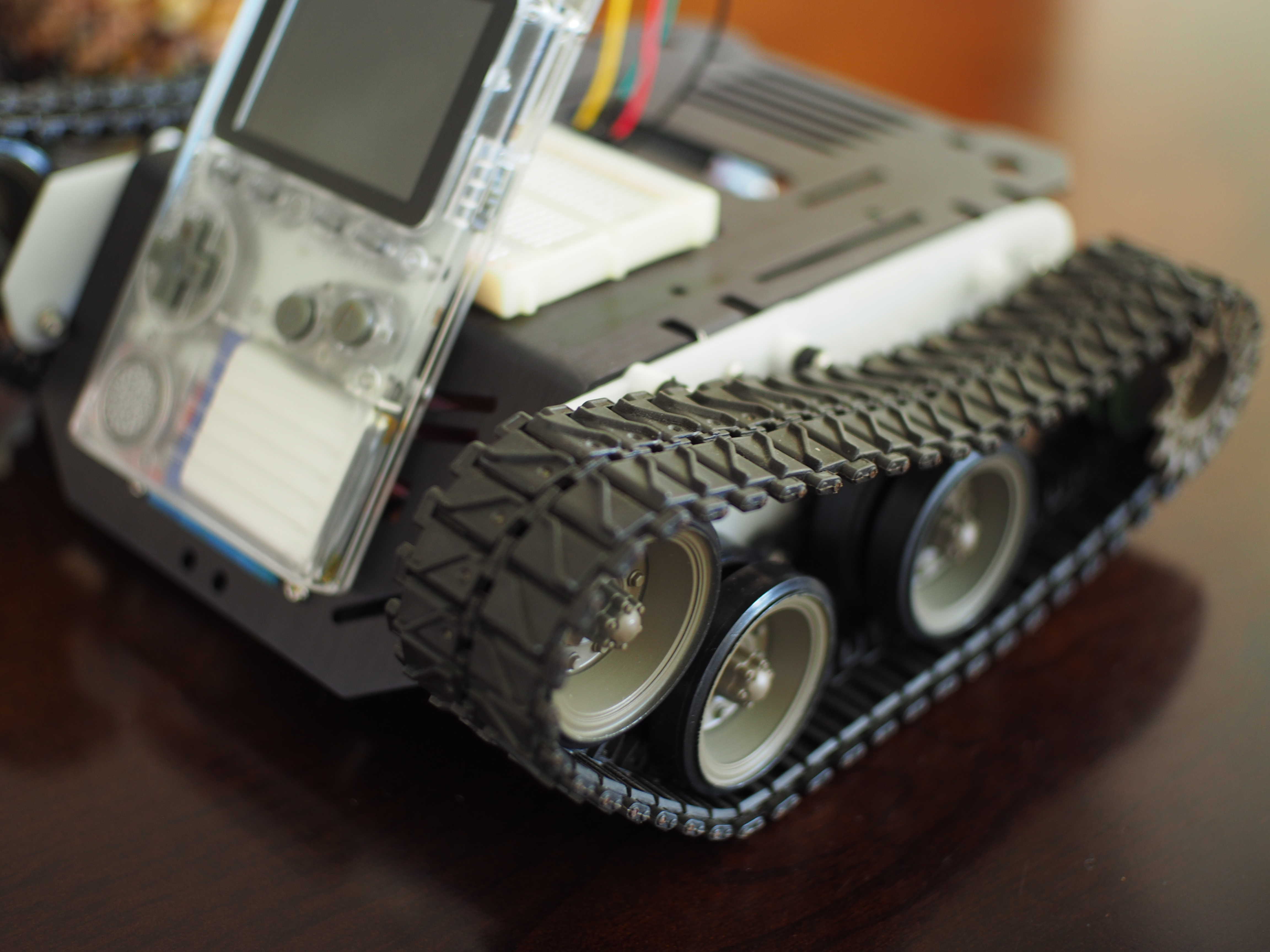
1. Out of the box, I didn’t think that the Devastator tank looked like a proper tank. Therefore, I created a pair of new lower hull side panels. These new panels enabled me to move the drive sprockets and motors to the rear of the robot.
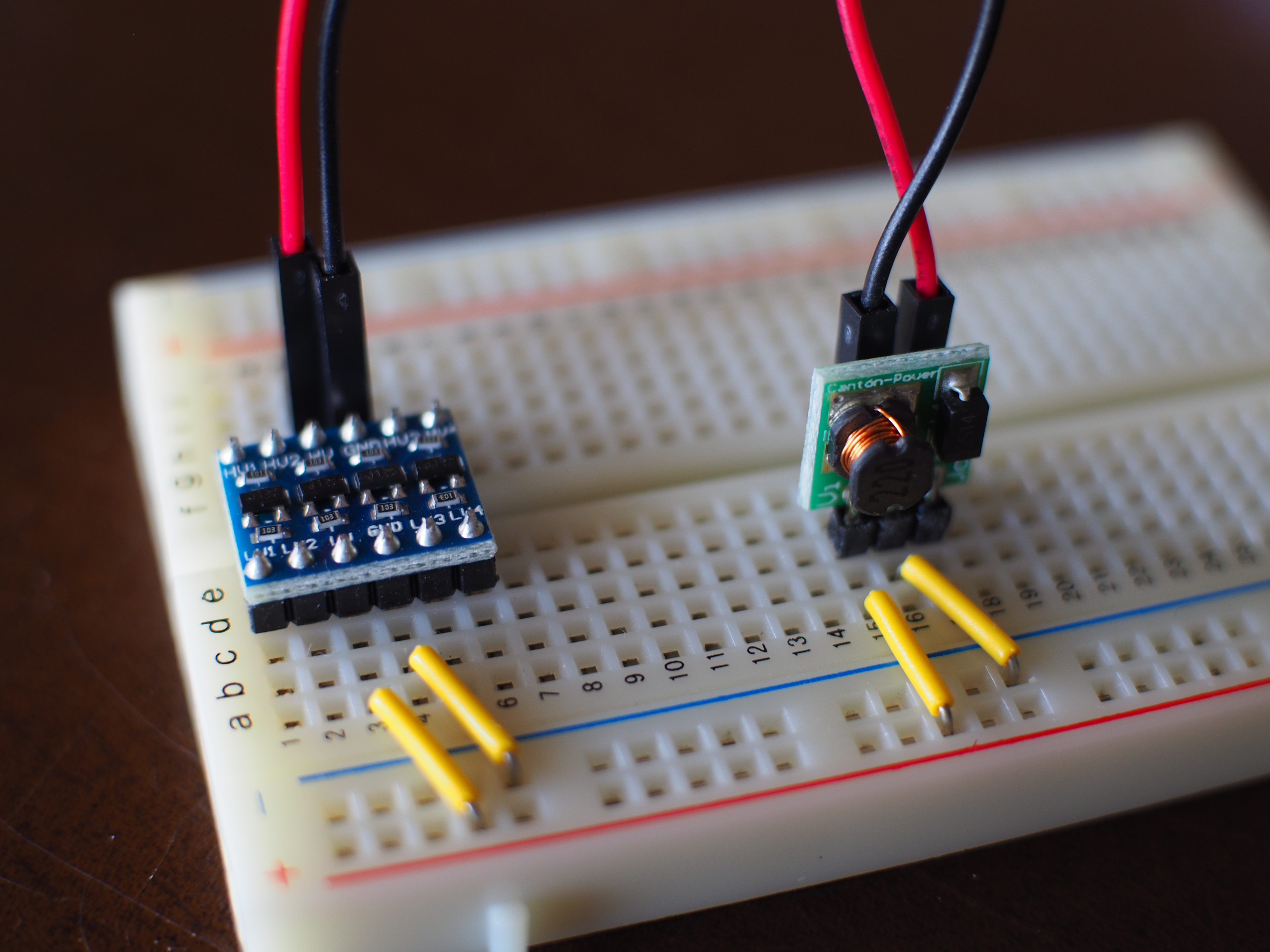
2. Follow the circuit design for the ODROID Ultrasonic Distance Meter wiki. This arrangement will allow the 3.3V GPIO pins on the ODROID-GO to control the 5V-powered transistorized power switch motor controls. In this case, the Step Up is used for powering the Level Shifter and NOT for powering the motors.
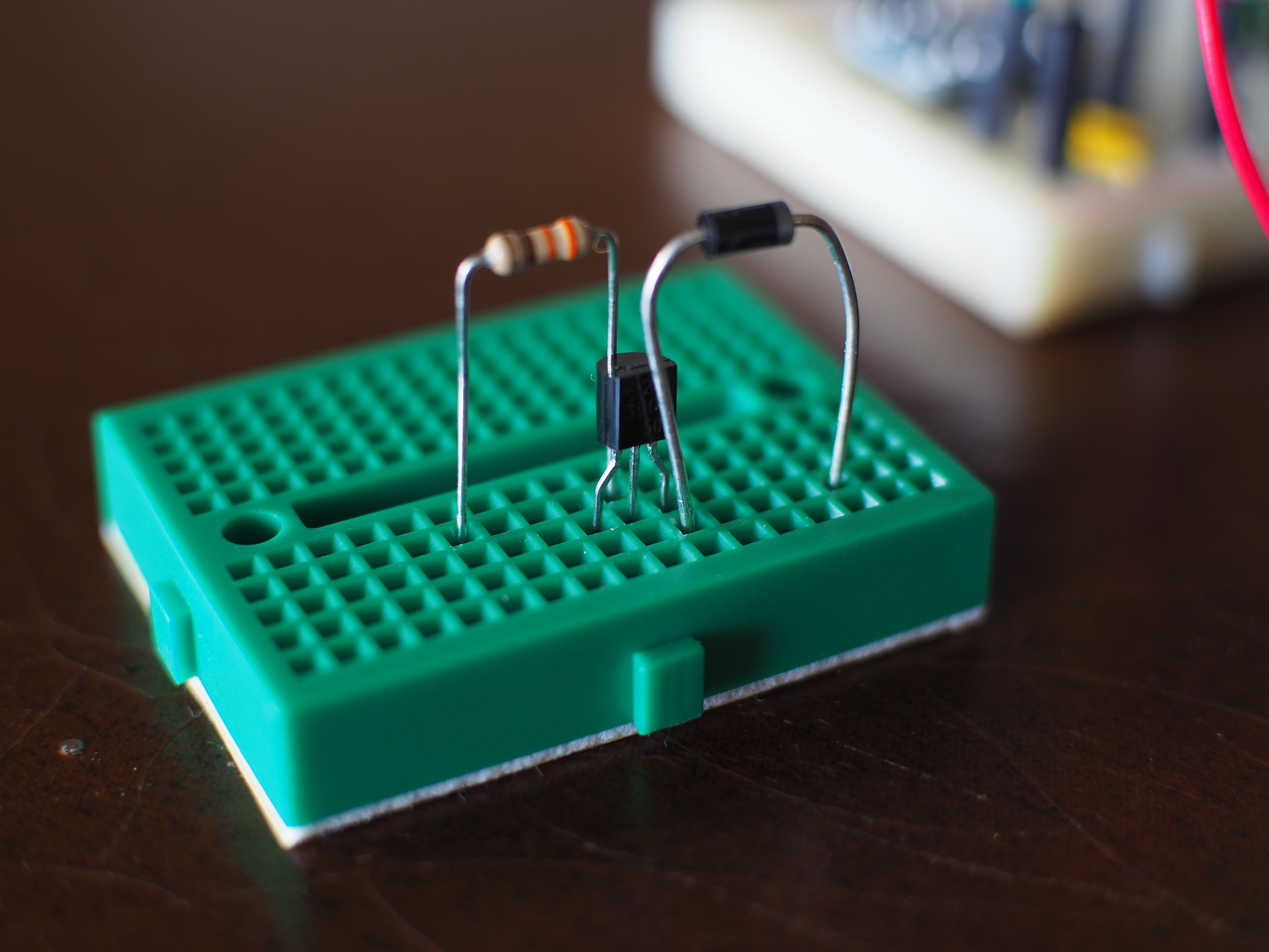
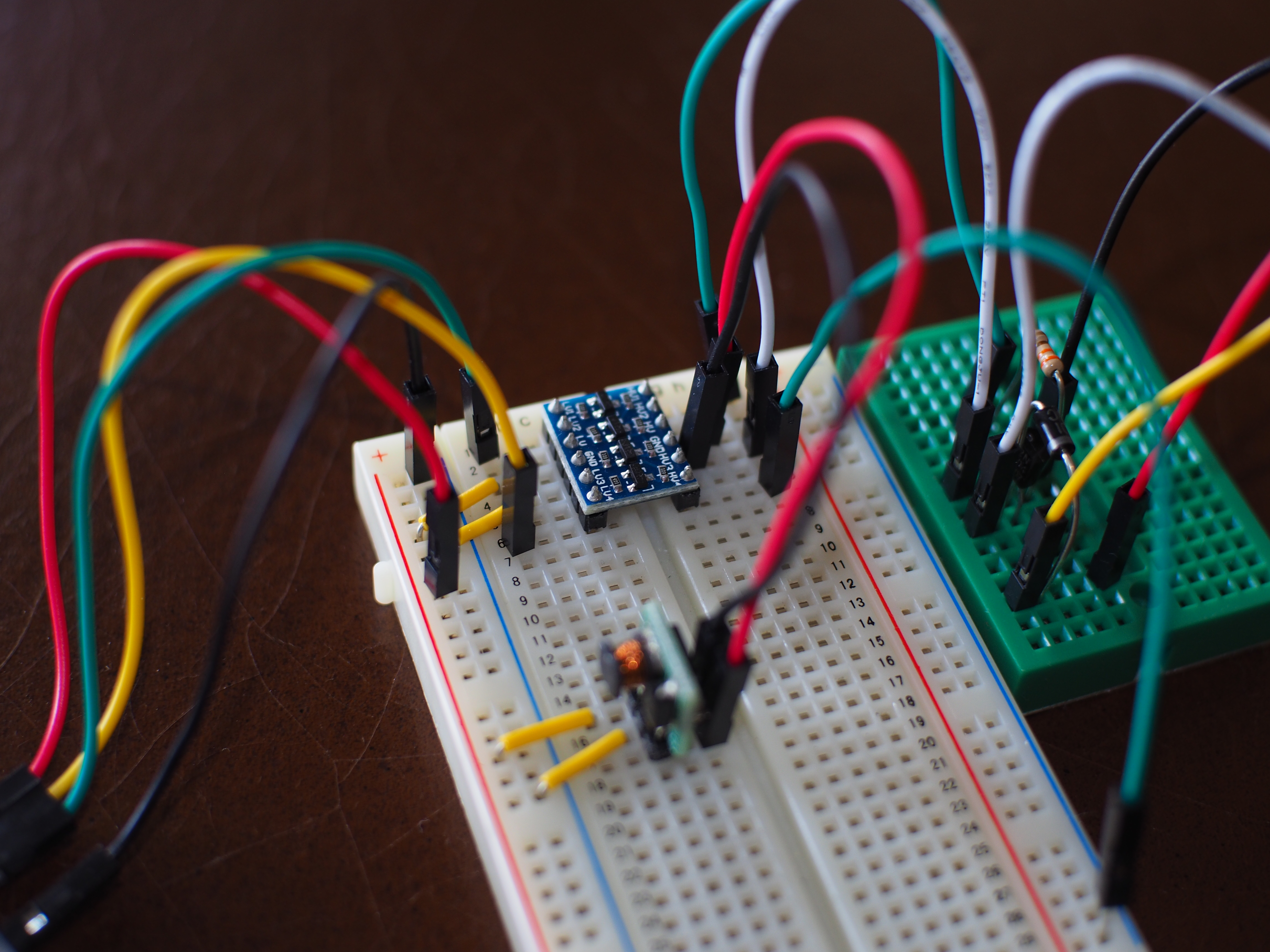
3. Wire two transistorized power switch motor controllers following the layout of this breadboard diagram (Figure 7) and photograph (Figure 7a):

4. Connect one of the motor controller outputs to one of the DC motors power lugs. Repeat for the other motor controller and connect it to the second DC motor. Connect a ground (GND; black) wire to the other, unconnected lug on each motor.
5. Wire the Devastator battery pack to both of the motor controllers (i.e., shown by the red and black GND wires in Figure 8). When a command is sent by one of the ODROID-GO GPIO pins, the transistors in these motor controllers will toggle the power from the battery pack directly into each motor. Sweet!
6. Program the ODROID-GO with code similar to these snippets:
#include
#include
#define PIN_MOTOR_RIGHT 15
#define PIN_MOTOR_LEFT 4
const char *apSSID = "ODROID_GO_AP";
const char *apPWD = "12345678";
WiFiServer server(80);
ILI9341 lcd = ILI9341();
void setup()
{
IPAddress gateway(192, 168, 4, 1);
IPAddress subnet(255, 255, 255, 0);
--snip--
Insert WiFi AP setup, LCD setup, and configure Web interface
Then add functions for defining left, right, forward movements like this:
void goFORWARD() {
lcd.setTextFont(4);
lcd.setTextSize(2);
lcd.setCharCursor(2, 5);
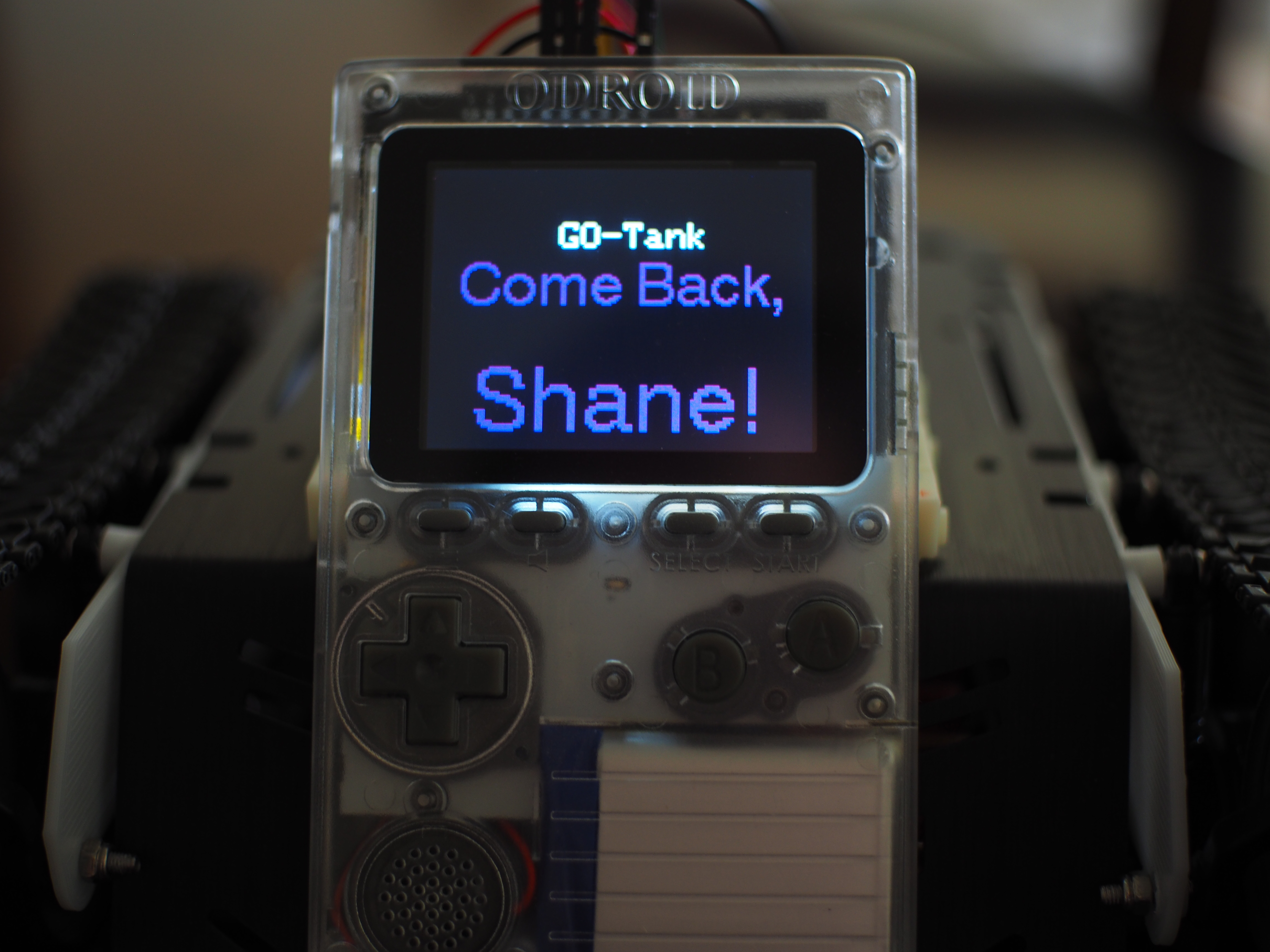
lcd.setTextColor(PURPLE, BLACK);
lcd.println("Come Back,");
lcd.setTextSize(3);
lcd.setCharCursor(2, 7);
lcd.println("Shane!");
digitalWrite(PIN_MOTOR_RIGHT, HIGH);
digitalWrite(PIN_MOTOR_LEFT, HIGH);
delay(2000);
digitalWrite(PIN_MOTOR_RIGHT, LOW);
digitalWrite(PIN_MOTOR_LEFT, LOW);
}
7. Place the Devastator robot on top of a small box for testing its operation.
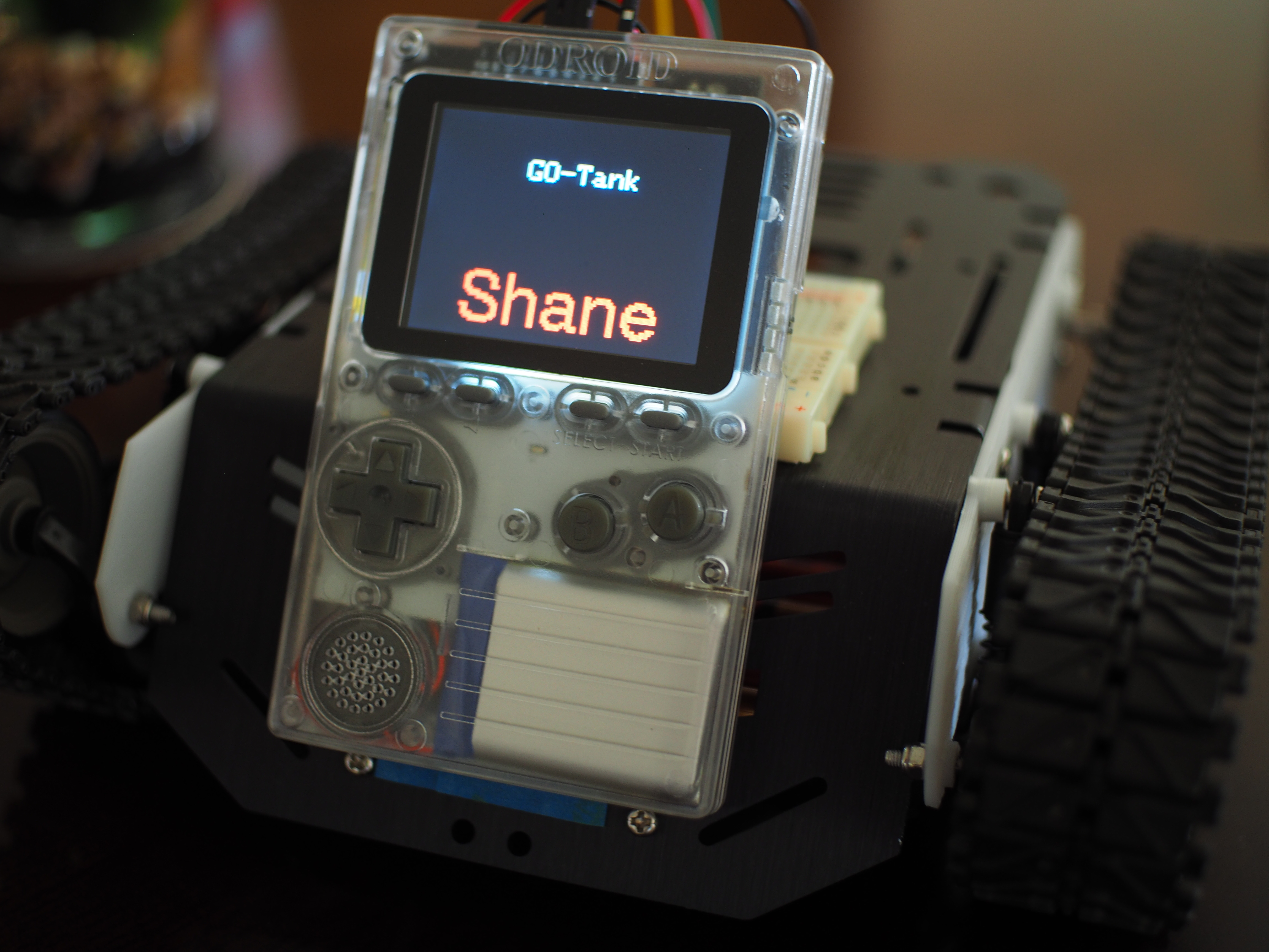
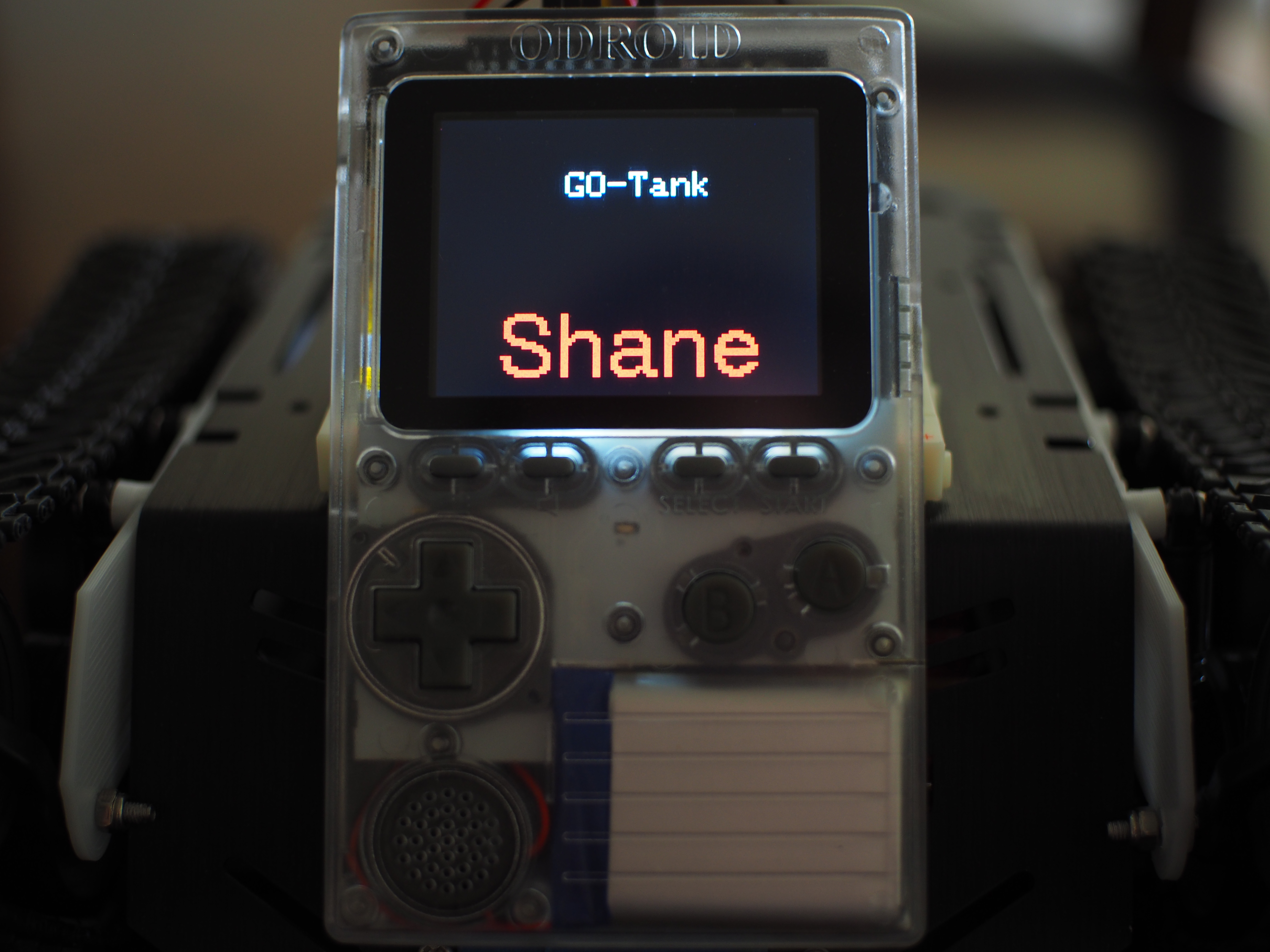
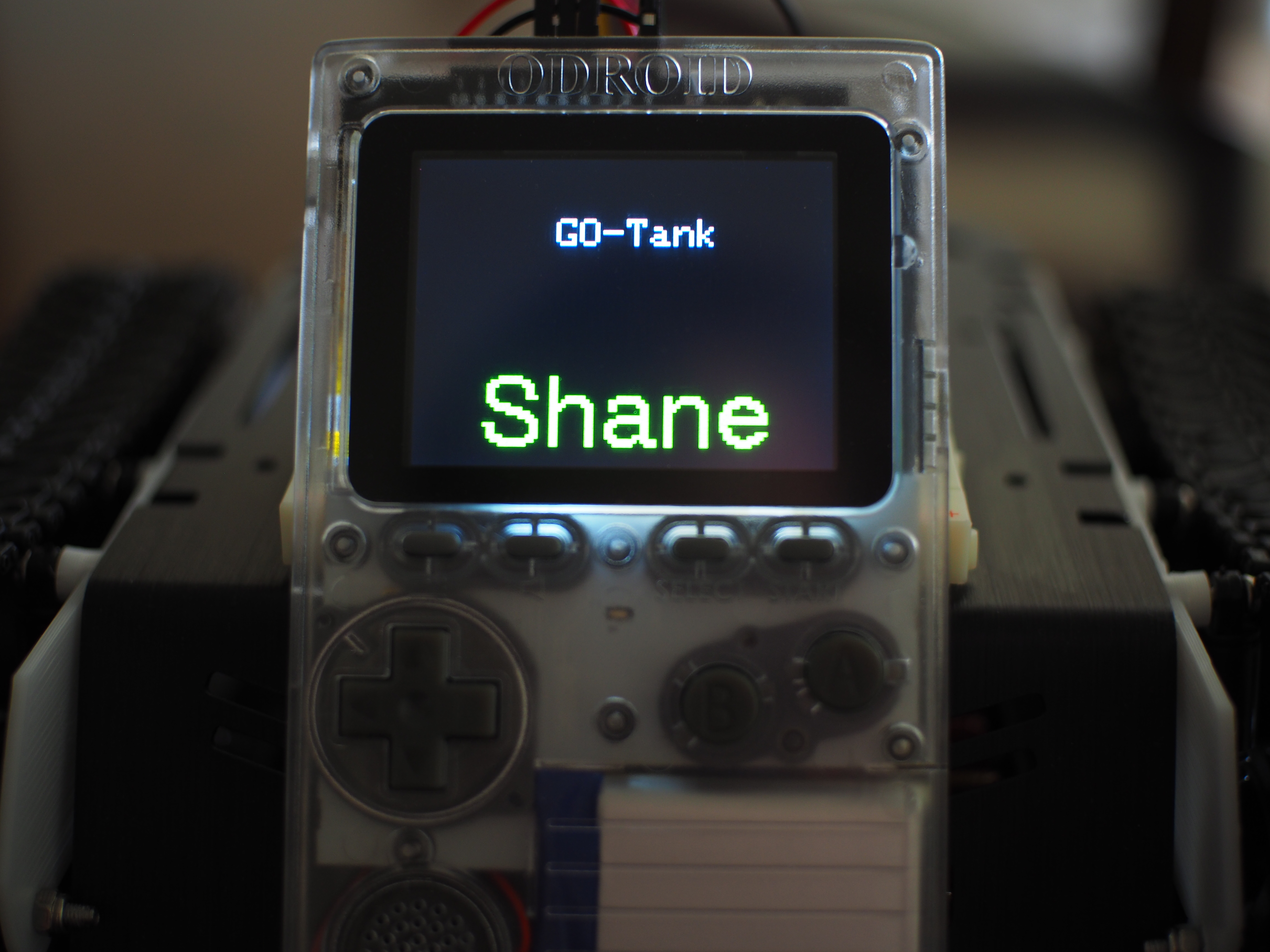
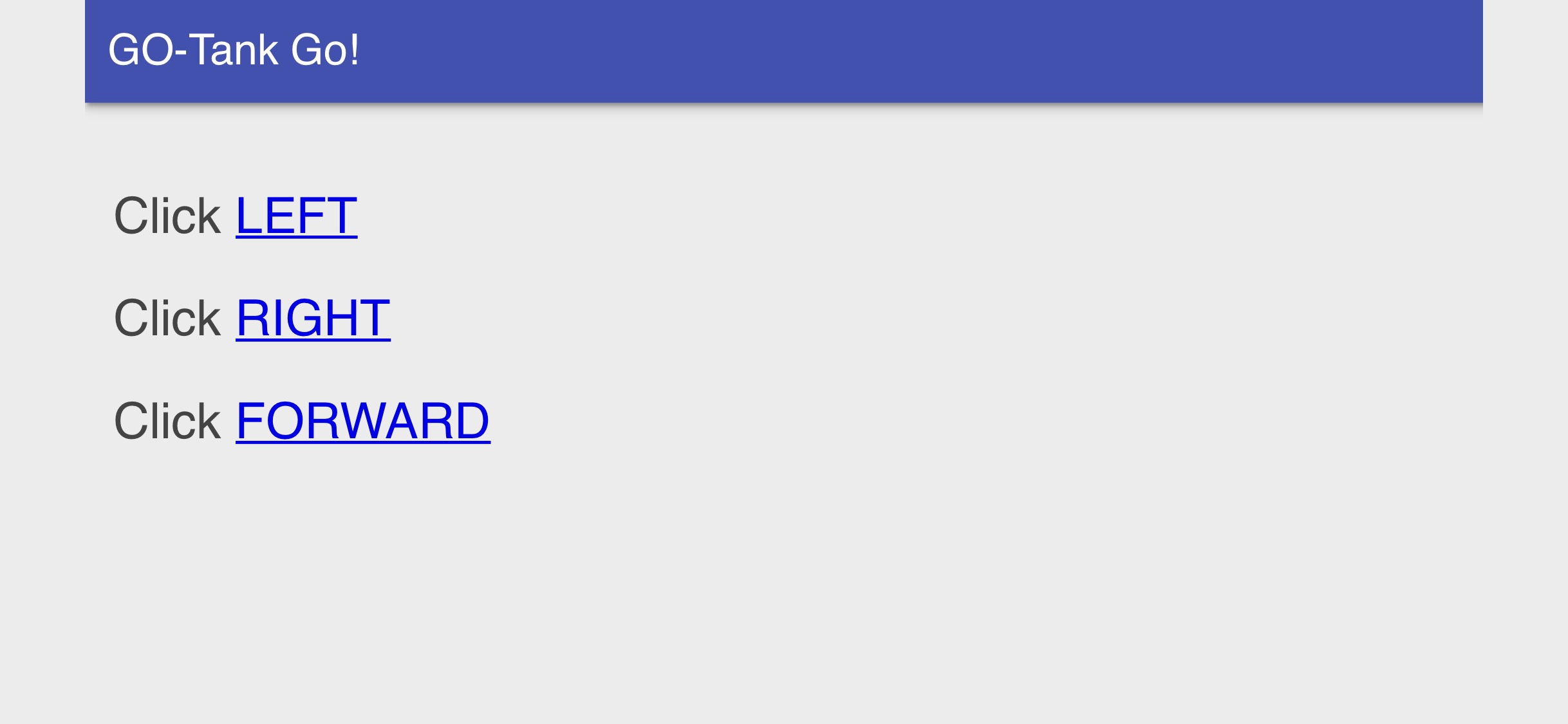
After switching on the ODROID-GO, connect your smart device to the ODROID-GO WiFi access point created inside the program’s code, and use your browser to load the code-generated Web page at: http://192.168.4.1. By pressing “LEFT” on this Web page, you should see a red display on the ODROID-GO and the left tread should move, this action will turn the tank right. Pressing “RIGHT” turns the display green and moves the tank left, while pressing forward runs both treads and drives the tank ahead.
Now get out there and enjoy your newfound freedom with a mobile ODROID-GO-Tank.
Notes
1. ALL ground (GND) lines must be connected together—regardless of voltages!
2. Why Shane? Read the 1949 Jack Schaefer classic Western novel, or watch the 1953 film adaptation starring Alan Ladd and wait for little Joey’s plaintive cry at the departing gunslinger.
Be the first to comment