

The ODROID-C1/C1+, ODROID-C2, and ODROID-XU4 have on-board GPIO (General Purpose Input/Output) pins that allow the control of external devices through software. In order to access the GPIO port properly, you must install the Android Marshmallow version 2.8 image or higher on the ODROID-C2, the Android KitKat version 3.2 image or higher on the ODROID-C1/C1+, and either the Android KitKat version 6.0 image or higher, or the Android Nougat version 1.3 20171214 image or higher on the ODROID-XU4.
This WiKi explains how to make an Android app which can access GPIO ports. You need to install Google Android Studio on your host PC. Add NDK and tools first before starting below steps. We tested the following steps on Android Studio 2.3 and NDK R14.
Ubuntu/Linux
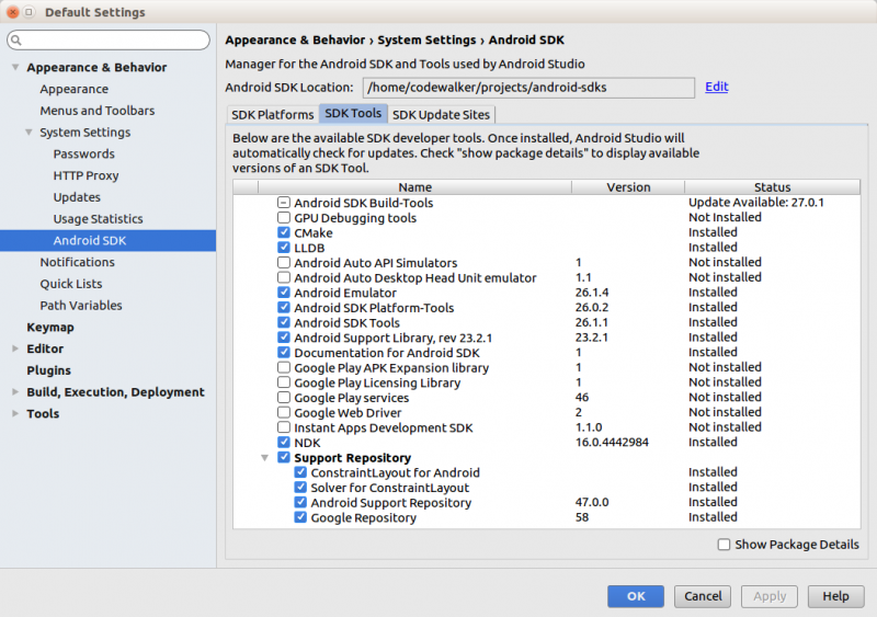
You can find the Android SDK location on this menu (File → Settings → Appearance & Behavior → System Settings → Android SDK)
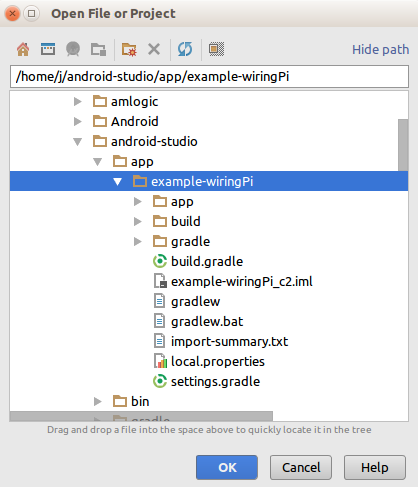
After editing the bashrc file, you have to login again or type “source ~/.bashrc” on the command line. Then, download the WiringPi NDK library and App source code Project from GitHub.
ODROID-C1+/C2
$ sudo apt install git
$ git clone https://github.com/codewalkerster/example-wiringPi -b odroid-c
ODROID-XU4
$ sudo apt install git
$ git clone https://github.com/codewalkerster/example-wiringPi -b odroid-xu
Run Android Studio and open the downloaded project.
Build the project to make an apk package
Select Build -> Make Project from the menu. You will see a couple of error messages, and will need to click the following options to complete the build process, which will produce an APK file to run on your ODROID:
- Install missing platform(s) and sync project
- Install Build Tools 25.0.2 and sync project
Windows
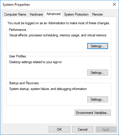
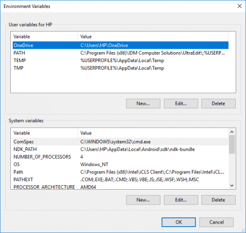
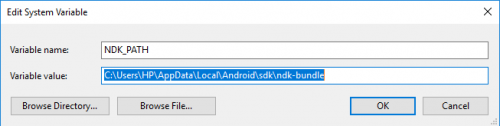
In Window, set the environment PATH to point to the NDK folder path, then reboot Windows.
Next, install the Git client program from https://git-for-windows.github.io/, and clone the wiringPi project, as shown in Figure 6.
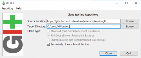
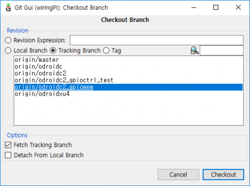
The project is available at https://github.com/codewalkerster/example-wiringPi. Select origin/odroid-c or origin/odroid-xu.
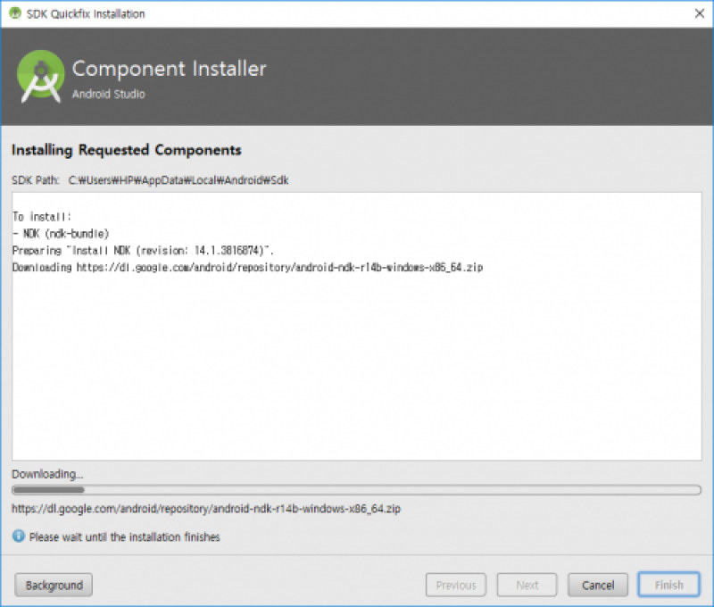
Then, install the NDK by selecting Tools -> Android -> SDK Manager from the menu.

Features of the example project
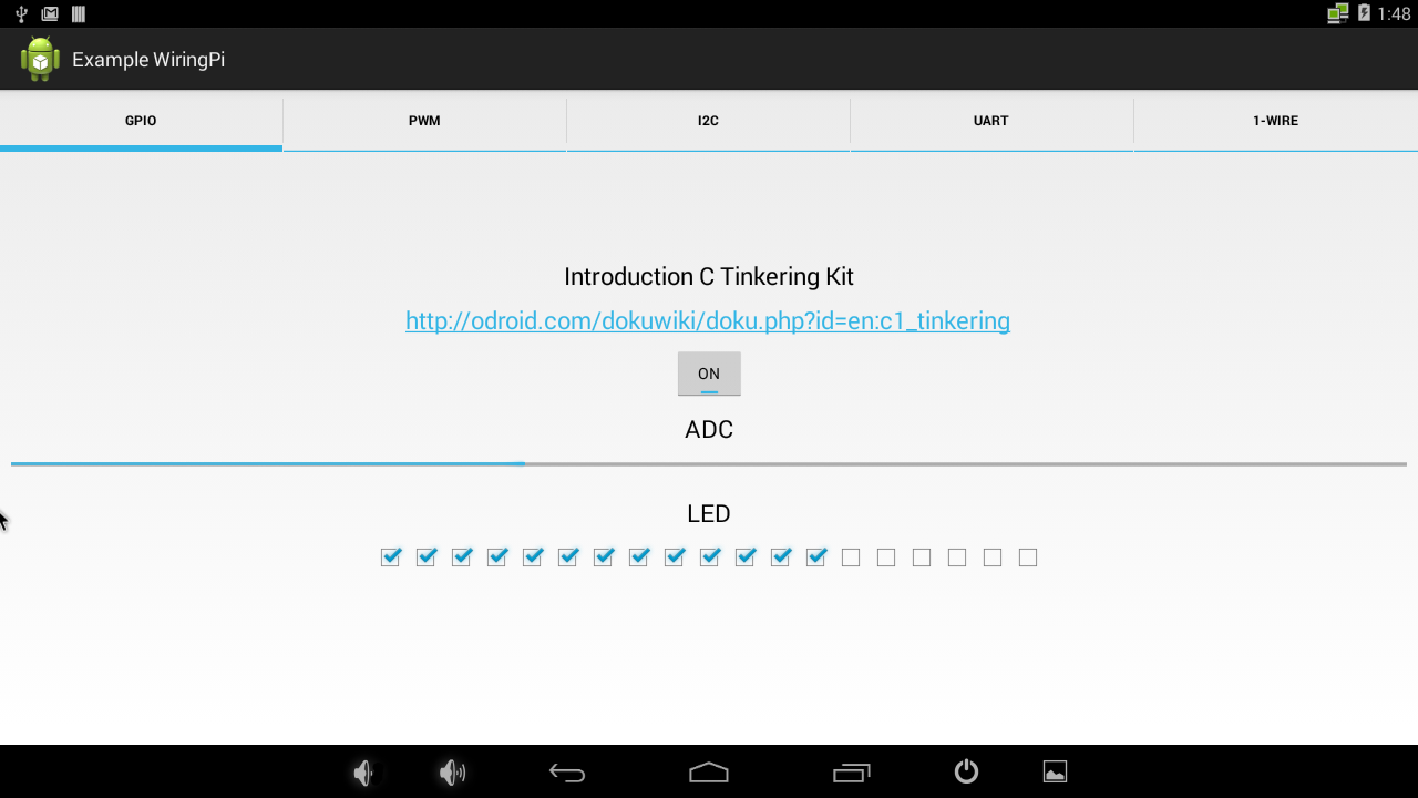
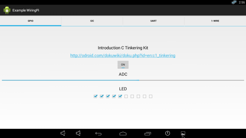
You can read the analog-to-digital converter (ADC) value and show the voltage level with 19 LEDs on the GPIO output. You can view a demo video at https://youtu.be/lGqyhvd3q9U and https://youtu.be/lGqyhvd3q9U.
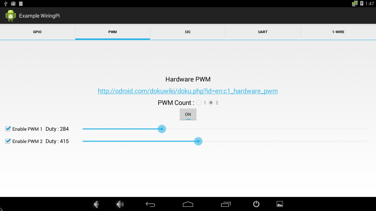
PWM
Figure 12 shows a basic PWM control example. You can choose the number of PWM outputs (1 or 2), as well as control the frequency and duty ratio.
Gmail Notifier example
This is a fun and useful project using the PWM port. When you are watching videos or playing games, you may miss notification of an important email or message. The flag is moved by servo motor which is connected to a PWM pin on 40pin GPIO port. The code may be downloaded from https://github.com/codewalkerster/GMailNotifier. A demo of the project may be viewed at https://youtu.be/Vvq77w87RWQ.
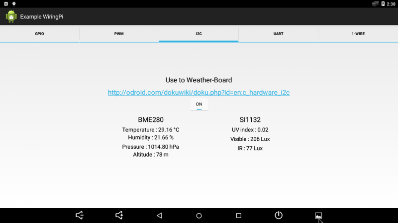
I2C
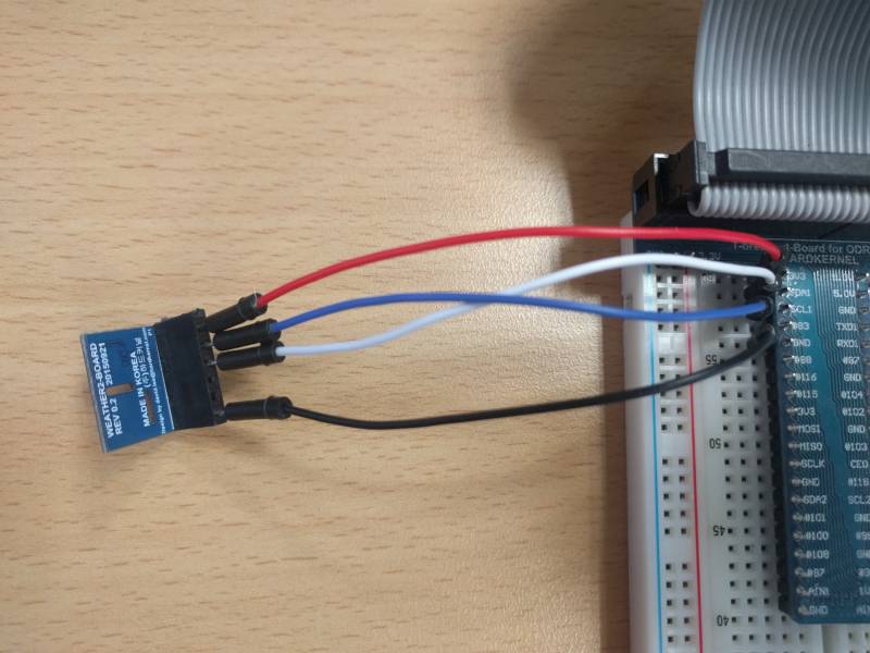
Figure 15 shows example code for accessing our Weather Board is available in order to measure the temperature, humidity, atmospheric pressure, altitude and visible/invisible light intensities via I2C interface.

Kernel for I2C
Open the File Manager app, and edit the file /storage/internal/boot.ini as shown below:
Original
movi read dtb 0 ${dtbaddr}
# load kernel from vat or boot partition.
movi read boot 0 ${loadaddr}
#fatload mmc 0:1 ${loadaddr} Image
booti ${loadaddr} - ${dtbaddr}
After edit
movi read dtb 0 ${dtbaddr}
# load kernel from vat or boot partition.
#movi read boot 0 ${loadaddr}
fatload mmc 0:1 ${loadaddr} Image
booti ${loadaddr} - ${dtbaddr}
Load the kernel image from the vfat partition built i2c. If you cannot find the “fatload” command, remove /storage/internal/boot.ini file and reboot the system. For comments, questions and suggestions, please visit the original Wiki article at https://wiki.odroid.com/odroid-c2/application_note/gpio/enhancement_40pins_on_android.
Be the first to comment