

Who would have guessed?! But, it’s there on page 1 of the Espressif ESP32 WROVER Datasheet: “There are two CPU cores that can be individually controlled, ...”
And another dual core reference can be found on page 7: “ESP32-D0WDQ6 contains two low-power Xtensa® 32-bit LX6 microprocessors.”
Well, that’s interesting to know, but how can these dual cores be used on the ODROID-GO? For example, how can a program written in the Arduino Integrated Development Environment (IDE) take advantage of the ESP32 dual cores?
It’s remarkably easy to use the dual cores inside the ODROID-GO, but first let’s gather some basic background information.
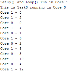
When a “traditional” Arduino sketch, meaning a program that contains the setup()and loop()function, runs it is only using one of the cores. That core is Core 1, the second core (starting from 0). You can prove this to yourself by adding the xPortGetCoreID()call to your setup and loop functions. When piped to the Serial Monitor of the Arduino IDE (see Figure 1), you should see the current core’s value, Core 1.

Now the original code used for the discovery and implementation of the dual cores in this article came from an article by Rui Santos at randomnerdtutorials.com and via a blog on February 14, 2019, and a post on SparkFun Electronics at sparkfun.com. If you’d like to learn some additional information about programming dual cores in Arduino, start with these two resources. Then you can enable your ODROID-GO to do two things at once.
Step-By-Step Instruction
1. Enter this example Arduino sketch:
/*
* Dual Core Demonstration for
* ODROID-GO
*
* Derived from code by Rui Santos
* at randomnerdtutorials.com
*
* Mentioned in SparkFun Electronics
* blog on February 14, 2019
* at sparkfun.com
*
* ODROID Magazine
* by Dave Prochnow
*/
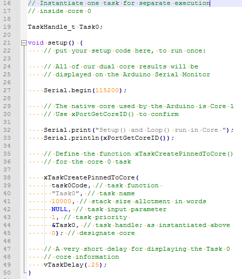
// Instantiate one task for separate execution
// inside core 0
TaskHandle_t Task0;
void setup() {
// put your setup code here, to run once:
// All of our dual core results will be
// displayed on the Arduino Serial Monitor
Serial.begin(115200);
// The native core used by the Arduino is Core 1
// Use xPortGetCoreID() to confirm
Serial.print("Setup() and Loop() run in Core ");
Serial.println(xPortGetCoreID());
// Define the function xTaskCreatePinnedToCore()
// for the core 0 task
xTaskCreatePinnedToCore(
task0Code, // task function
"Task0", // task name
10000, // stack size allotment in words
NULL, // task input parameter
1, // task priority
&Task0, // task handle; as instantiated above
0); // designate core
// A very short delay for displaying the Task 0
// core information
vTaskDelay(.25);
}
// Create the core 0 task function; which will run
// forever
void task0Code( void * pvParameters) {
Serial.print("This is Task0 running in Core ");
// Label the core with xPortGetCoreID
Serial.println(xPortGetCoreID());
int x = 0;
String xPreamble = "Core 0 - ";
// You can create an infinite loop with for(;;)
for(;;){
Serial.println(xPreamble + x);
x++;
}
}
void loop() {
// put your main code here, to run repeatedly:
// This function will run in Core 1
int y = 0;
String yPreamble = "Core 1 - ";
for(;;) {
Serial.println(yPreamble + y);
y = y + 2;
}
}
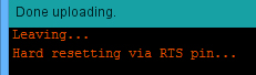
2. Compile this program and upload it to the ODROID-GO (see Figure 2).
3. Leave the ODROID-GO connected to your PC and immediately, switch OFF the power switch.
4. Now open the Serial Monitor and set the baud rate to 115200 as shown in Figure 3.
5. Toggle the ODROID-GO power switch ON-OFF very quickly. This fast switching will enable just a short burst of dual core information to be sent to the Serial Monitor.
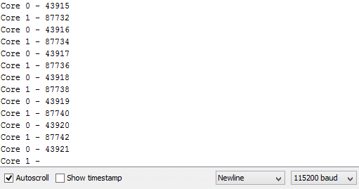
6. Scroll up to the top of the Serial Monitor print out and review the lines that are printed after the ESP32 startup information. You should see a couple of core IDs and a long list of incrementing values that are being calculated by each core similar to the display in Figure 4.
7. Now adapt this technique to your own Arduino challenges (see Figure 5) and teach your ODROID-GO how to walk and chew code and the same time.
Be the first to comment