

Digole.com offers several intelligent serial displays that are controlled through a complete set of high-level proprietary commands. These commands make drawing complex graphics and displaying images and video much easier, offering a offer a layer of abstraction that makes it easy to port their displays to a number of different platforms. Perhaps the most useful is that all of Digole’s models of serial displays are controlled in the same manner, with the same high level command set, and are firmware-upgradeable. The user manual at http://bit.ly/2fXiD9y provides complete documentation of all available commands.
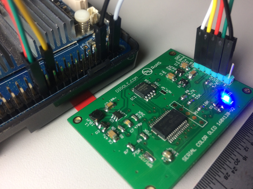
For this article, I used a Digole 1.8 inch Serial UART/I2C/SPI True Color 160x128 OLED Module with 2MB Flash, model number DS160128COLED-46F. This model does not have a backlight or touchscreen like some of the other thin film transistor (TFT) displays. If you buy a different model, you may have to modify the source code in order to change the screen resolution.
All of the following was done on an ODROID-C1+ running the official Ubuntu 16.04 minimal image and logged in as root.
Initial Test via UART Serial Connection
The Digole serial display ships in UART mode (both SPI and I2C jumpers open). It’s always 8 bits, no parity bit, 1 stop bit. The initial, user-configurable baud rate is 9600.
With the ODROID turned off, wire up the following:
Digole VCC = 5V GPIO pin 2 Digole GND = Ground GPIO pin 6 Digole DATA = TXD1 GPIO pin 8
Power on the ODROID. The Digole should immediately go through its own boot process, which involves an RGB test and ends in a line of text. My display showed “UART baud:9600 V4.1V+2MB Flash”. V4.1V is the firmware version, 2MB Flash is how much flash memory is available on this particular display model. Not all models have flash memory.
Set the UART device’s baud rate:
$ stty -F /dev/ttyS2 9600Clear the screen with:
$ echo “CL” > /dev/ttyS2For this next command, use single-quotes--not smart-quotes or backticks--so that the \x00 terminator is handled correctly:
$ echo -n -e ‘TTHello ODROID\x00’ > /dev/ttyS2
$ echo “CL” > /dev/ttyS2
Draw a 45px x 45px square:
$ echo -n -e ‘DR\x00\x00\x2D\x2D’ > /dev/ttyS2Since this is a test, we don’t need to learn Digole’s coordinate syntax right now.
At this point, the display is considered fully functional. It is possible to use Digole’s proprietary commands to completely control the display just by echoing to the UART device. This means one could write an app or game entirely in Bash script or any programming language that can pipe directly to the UART device, including PHP, Perl, Ruby, and Python, although probably with a higher baud rate. With this approach, one can avoid coding in C and using the Digole C library.
We will be testing other methods of serial connection, so shut down the ODROID and remove the power plug to cut power to the Digole display, then remove the Digole’s connections to the GPIO pins.
I2C Serial Connection
Using a soldering iron with a tiny conical tip, carefully jump the I2C jumper while leaving the SPI jumper open. It is important not to solder both jumpers by bridging all three pads. This requires a sharp eye or microscope, and a steady hand. With the ODROID turned off, wire up the following:
Digole VCC = 5V GPIO pin 2 Digole GND = Ground GPIO pin 6 Digole DATA = I2CA_SDA GPIO pin 3 Digole CLK = I2CA_SCL GPIO pin 5
Note that the User Manual has diagrams with resistors of 10K or greater between VCC and DATA and VCC and CLK, but the the sample code diagrams on the webpage do not have any resistors. I found that it worked well enough without the resistors, so I did not test to see if the resistors worked.
Next, power up the display. If you soldered the I2C jumper correctly, the startup test will say “I2C address:0x27...” The startup test doesn’t appear to know if DATA and CLK are wired up correctly.
Enable I2C on the ODROID by running:
$ modprobe aml_i2cTo test I2C, we will use the Digole sample C code provided at http://bit.ly/2xh29MJ.
The sample code was written by Javier Sagrera for the Raspberry Pi. We can modify it for the ODROID with a few small changes; nothing critical, just re-naming a few Raspberry Pi references and correcting misspellings, as shown below:
// Pin-out using I2C
// ODROID – Digole LCD
// 1: 5v = 5: VCC
// 3: SDA0 = 4: DATA
// 5: SCL0 = 3: CLK
// 6: GND = 1: GND
/*

// Communication set up command
* "SB":Baud (ascII bytes end with 0x00/0x0A/0x0D) -- set UART Baud Rate
* "SI2CA":Address(1 byte <127) -- Set I2C address, default address is:0x27
* "DC":1/0(1byte) -- set config display on/off, if set to 1, displayer will display current commucation setting when power on

// Text Function command
* "CL": -- Clear screen--OK
* "CS":1/0 (1 byte)-- Cursor on/off
* "TP":x(1 byte) y(1 byte) -- set text position
* "TT":string(bytes) end with 0x00/0x0A/0x0D -- display string under regular mode

// Graphic function command
* "GP":x(1byte) y(1byte) -- set current graphic position
* "DM":"C/!/~/&/|/^"(ASCII 1byte) -- set drawing mode--C="Copy",! and ~ = "Not", & = "And", | = "Or", ^ = "Xor"
* "SC":1/0 (1byte) -- set draw color--only 1 and 0
* "LN":x0(1byte) y0(1byte) x1(1byte) y2(1byte)--draw line from x0,y0 to x1,y1,set new pot to x1,y1
* "LT":x(1byte) y(1byte) -- draw line from current pos to x,y
* "CC":x(1byte) y(1byte) ratio(byte) -- draw circle at x,y with ratio
* "DP":x(1byte) y(1byte) Color(1byte) -- draw a pixel--OK
* "DR":x0(1byte) y0(1byte) x1(1byte) y2(1byte)--draw rectangle, top-left:x0,y0; right-bottom:x1,y1
* "FR":x0(1byte) y0(1byte) x1(1byte) y2(1byte)--draw filled rectangle, top-left:x0,y0; right-bottom:x1,y1
*/

#include < stdlib.h >
#include < linux/i2c-dev.h >
#include < fcntl.h >
#include < string.h >
#include < sys/ioctl.h >
#include < sys/types.h >
#include < sys/stat.h >
#include < unistd.h >

int main(int argc, char **argv)
{
   int fd;
   char *fileName = "/dev/i2c-1";      // Name of the port we will be using
   int  address = 0x27;                // Address of I2C device
   char buf[100];

   if ((fd = open (fileName, O_RDWR)) < 0) { // Open port for reading and writing
       printf("Failed to open i2c port\n");
       exit(1);
   }

   if (ioctl(fd, I2C_SLAVE, address) < 0) { // Set the port options and set the address of the device printf("Unable to get bus access to talk to slave\n"); exit(1); } if (argc>1) {
       sprintf(buf,argv[1]);
       //printf("%s %d %s\n",buf,strlen(buf),buf[strlen(buf)]);
       if ((write(fd, buf, strlen(buf)+1)) != strlen(buf)+1) {
           printf("Error writing to i2c slave\n");
           exit(1);
       }
   } else {
       printf(" Simple tool to send commands to Digole graphic adapter\nexamples:\n");
       printf(" digolei2ctest \"CLTTHello ODROID\" - Clear the screen (CL) and prints \"Hello ODROID\" (TT)\n");
       printf(" digolei2ctest \"CC002\" - Draws a circle at x=30 (0), y=30 (0) with a radius of 32 (2)\n");    //not for Character LCD
   }

   return 0;
}
Save the above source code as digolei2ctest.c, then compile it:
$ gcc -o digolei2ctest digolei2ctest.cYou can then run it to send commands (several are provided in the comments):
$ ./digolei2ctest "CLTTHello ODROID"
$ ./digolei2ctest "CC002"
Again, you can use every high-level command available in the User Manual.
Note: I2C is the only means of communicating with the Digole serial display that is capable of two-way communication. Considering that we are only drawing on the display, receive capability is not necessary, but I2C is probably required for touchscreen access.
Next, we will try the SPI method of communication. This is the fastest, but most complicated, of available serial methods. Once again, shut down the ODROID and remove the power plug to turn off the Digole display, then disconnect the connections between the ODROID and the Digole display.
SPI 3-Wire Serial Connection
Using a soldering iron with tiny conical tip, carefully desolder the I2C jumper and replace it by soldering the SPI jumper instead. Again, make sure not to solder both jumpers by bridging all three pads. With the ODROID turned off, wire up the following:
Digole VCC = 5V GPIO pin 2 Digole GND = Ground GPIO pin 6 Digole DATA = MOSI_PWM1 GPIO pin 19 Digole CLK = SPI_SCLK GPIO pin 23 Digole SS = SPI_CEN0 GPIO (#117) pin 24
Power on the ODROID. The Digole startup text should start with “SPI Mode:0...” if you soldered the SPI jumper correctly. It does not seem to know whether DATA, CLK, or SS are wired correctly.
Note that Digole states in the manual that SPI mode has the additional requirement of a "special handshake" to "clock out data." Check the “SPI transceiver data flow chart” at the end of the Port Connection section of the Digole serial display User Manual for details. For SPI testing, we will be using James F. Dougherty’s driver and sample code at http://bit.ly/2wmyPIi.
This script is also written for the Raspberry Pi, but works without modification on the ODROID-C1+. The only difference is the pinout: connect the Digole SS pin to GPIO pin 24 on the ODROID-C1+ instead of GPIO pin 26 on a Raspberry Pi.
Enable SPI on the ODROID:
$ modprobe spiccThen obtain and build Dougherty’s SPI driver:
$ git clone https://github.com/jafrado/digole.git
$ cd digole
$ make
Run the included test code:
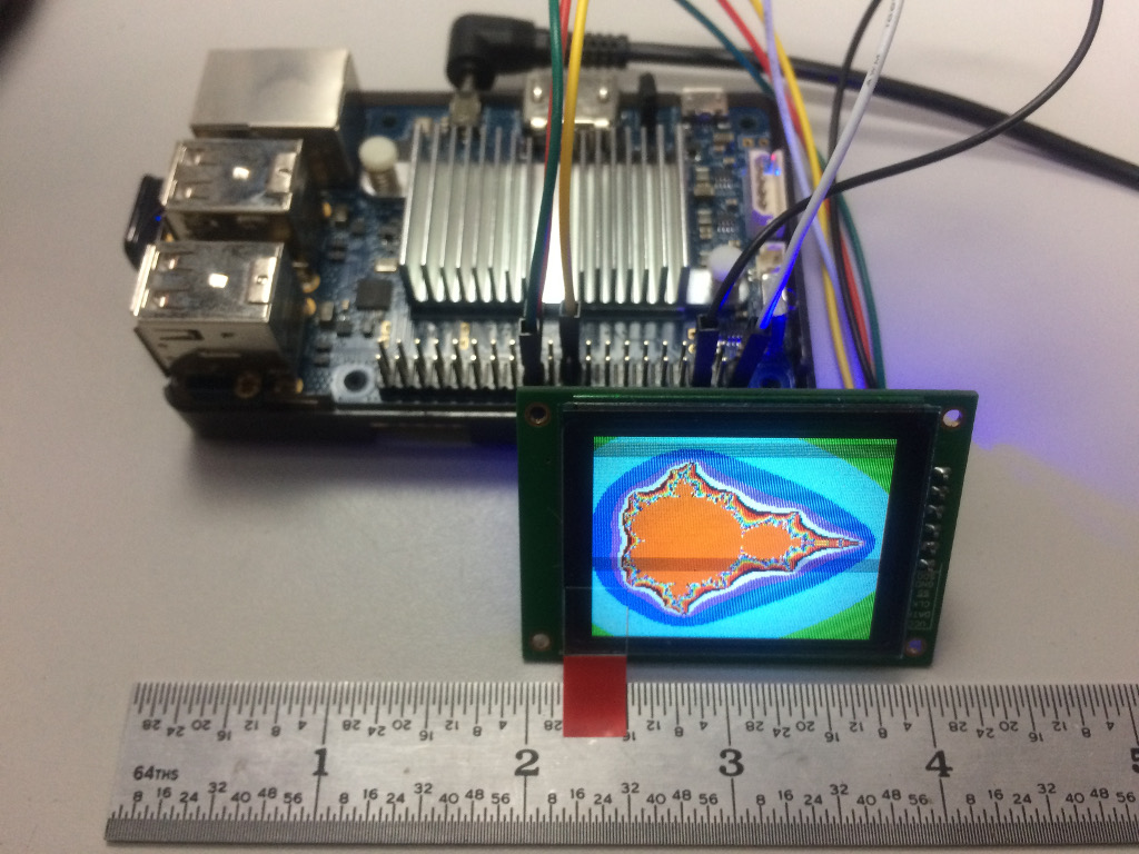
$ ./oledtest /dev/spidev0.0You should see the display start with an image of a compass followed by many test screens. Don’t worry about the slow drawing speed, since a way to increase it will be described in the next section. Try the other sample program to display a Mandelbrot fractal:
$ ./mandel /dev/spidev0.0There are other sample programs, but they appear to be slightly buggy and tend to draw their graphics in unexpected positions. At this point, between the oledtest.c and mandel.c programs, you should have all you need to start building your own apps that use the Digole serial displays.
Performance Considerations
In Dougherty’s code, change the spi_speed value at rpi_spi.c line 41 from 200,000 to 1,000,000 (1MHz) to increase the speed at which the images are displayed on the screen. Going faster than 1MHz breaks the drawing commands badly on my ODROID-C1+. Dougherty commented in the code that he was not able to go faster than 200KHz, but he was using a very slow Raspberry Pi Zero for testing.
Curious about the limitation, I used a simple while loop with a “sleep x” command and varying values of x in order to overwhelm the Digole display by sending sentences of commands too quickly, causing mis-drawn graphics or corrupt images, which is exactly what happened when “spi_speed” value was increased above 1MHz in Dougherty's sample programs. Theoretically, the SPI bus and the Digole display can go much faster than 1MHz, but I suspect that the aforementioned “special handshake” and precise management of SPI communications at the byte and word level will be necessary to achieve maximum performance.
We do know, however, that these displays are capable of performing very well. Digole links to a YouTube video at http://bit.ly/2wfwPRJ showing a fast, smooth video sequence of 27 frames in about 2 seconds, which is approximately 14fps.
Unfortunately, they do not detail in the video how to achieve this speed. The title of the video indicates they are using the relatively new Video Box feature (as of firmware V4.0V) which allows one to write raw image data directly to the display. The User Manual says Video Box runs at “maximum speed: UART mode-460800bps, I2C->400K bps, SPI-10MHz." That's ten times faster than our current best performance using Dougherty's samples in SPI mode. It will probably require contacting Digole tech support to find out how to pull it off.
Regarding the while loop tests, a “sleep 0.05” command appears to be the shortest delay between "TP00TTHello ODROID\x00" sends, resulting in a barely-perceptible flicker of the words "Hello ODROID" being redrawn in place with no errors. For many projects, especially those that update text periodically, 0.05 seconds is plenty fast enough, and one will not have to wrestle with performance tuning of the serial communications.
Conclusion
I’m quite impressed with the Digole serial displays for their multiple connection methods and easy, but powerful, commands. There are many advanced features including stored fonts, stored command sequences, and integrated touchscreen that other, less intelligent, displays simply don’t have. Most other touchscreens are a separate device from the display, but the Digole touchscreen is controlled through the same serial interface as the display. The simple fact is that there aren’t that many full-color, high-resolution displays in this small of a size, especially in OLED.
I expect that these tiny full-color displays will find their way into many ODROID projects, especially portable, battery-powered projects. This is especially true of the models with resistive touchscreens and the handful of TFT models with dimmable backlights. OLED models do not have a backlight to dim, but dimming can be accomplished by changing the colors to darker shades.
The performance of the Digole serial displays is good enough for most uses without any performance tuning. For games and video where frame rate matters, it is certainly possible to achieve decent performance through managing the serial communications management and by taking advantage of the Digole display’s advanced features.
Be the first to comment