

Let us learn how to control the blue LED on ODROID-GO front side by tinkering the LED with simple GPIO on/off as well as 256-steps brightness control with PWM. Before we begin, please make sure you have read the first two guides at https://wiki.odroid.com/odroid_go/arduino/01_arduino_setup and https://wiki.odroid.com/odroid_go/arduino/02_hello_world. Additionally, the original guide can be found on the ODROID-GO wiki page at https://wiki.odroid.com/odroid_go/arduino/03_blue_led_and_pwm.
Blink the blue LED

Let's make the LED blink continuously. First, open a new sketch by pressing the shortcut CTRL-N. Controlling the LED very easy, the pin number for the LED is 2, so let’s define that with a Preprocessor. Next, we have to set the pin to output mode. Use the pinMode() function to do that.
#define PIN_BLUE_LED 2

void setup() {
// put your setup code here, to run once:

pinMode(PIN_BLUE_LED, OUTPUT);
}

void loop() {
// put your main code here, to run repeatedly:
}
Now the pin is ready to use. You can set the pin signal level by using the digitalWrite() function. This function has to be in loop() to run repeatedly. The delay() function is used to slow down the rate of blinking.
#define PIN_BLUE_LED 2

void setup() {
// put your setup code here, to run once:

pinMode(PIN_BLUE_LED, OUTPUT);
}

void loop() {
// put your main code here, to run repeatedly:

digitalWrite(PIN_BLUE_LED, HIGH);
delay(500);
digitalWrite(PIN_BLUE_LED, LOW);
delay(500);
}
Press CTRL-U to compile and upload the sketch. Then, you can see the blue LED blinking.
Give the LED a breathing effect
By adjusting the analog output value, we can make the LED show a breathing effect. This technique is known as PWM. Arduino gives us wrappers that help control the GPIO pins as well as the PWM features. Generally, these PWM functions are analogRead() and analogWrite(), but they are not yet available in ESP32 so we must use the ledcRead() and ledcWrite() functions to control the LEDs.
The way to control the PWM values in a ESP32 is different from other Arduino boards. These functions use the LED PWM hardware feature of ESP32 which is located in ledc.h, LED Control function header. In ESP32, the LED PWM is composed of 16 independent channels, and we can configure them with a duty cycles with a resolution and wave period.
First, we should choose a channel to attach the LED to. Channels 0 to 7 are available, we will use channel 1 in this example. Define the channel and the blue LED through a Preprocessor macro.
#define PIN_BLUE_LED 2
#define PWM_CHANNEL 1

void setup() {
// put your setup code here, to run once:
}

void loop() {
// put your main code here, to run repeatedly:
}
Set the pin mode of the LED to output:
#define PIN_BLUE_LED 2
#define PWM_CHANNEL 1

void setup() {
// put your setup code here, to run once:
pinMode(PIN_BLUE_LED, OUTPUT);
}

void loop() {
// put your main code here, to run repeatedly:
}
Attach the LED pin to the channel we defined. Next, set up the channel to operate at 12kHz with 8 bit resolution.
#define PIN_BLUE_LED 2
#define PWM_CHANNEL 1

void setup() {
// put your setup code here, to run once:
pinMode(PIN_BLUE_LED, OUTPUT);
ledcSetup(PWM_CHANNEL, 12000, 8);
}

void loop() {
// put your main code here, to run repeatedly:
}
Lastly, add the breathing code into the loop() function. We defined a variable called pinVal as a global variable to prevent allocating new memory repeatedly in the loop() function. The type of pinVal is an unsigned char since the PWM value ranges only 0-255.
#define PIN_BLUE_LED 2
#define PWM_CHANNEL 1

unsigned char pinVal = 0;

void setup() {
// put your setup code here, to run once:

pinMode(PIN_BLUE_LED, OUTPUT);
digitalWrite(PIN_BLUE_LED, HIGH);

ledcAttachPin(PIN_BLUE_LED, PWM_CHANNEL);
ledcSetup(PWM_CHANNEL, 12000, 8);
}

void loop() {
// put your main code here, to run repeatedly:

for (; pinVal > 0; pinVal--) {
ledcWrite(PWM_CHANNEL, pinVal);
delay(3);
}
for (; pinVal < 255; pinVal++) {
ledcWrite(PWM_CHANNEL, pinVal);
delay(3);
}
}
Press CTRL-U to compile and upload the sketch, then you can see the blue LED breathing.
A completed example
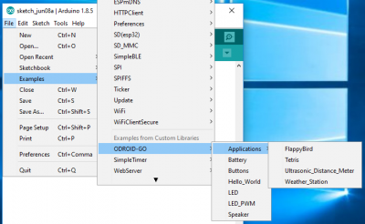
The complete example is available can be loaded in the Arduino IDE by clicking the Files → Examples → ODROID-GO → LED or LED_PWM menu to import and press CTRL-U to compile and upload.
Additional information
For extra information and help, please use the following links, or ask on the ODROID forums:
- Refer to the Arduino official documents. This provides useful common functions with great instructions.
- Refer to the ESP32 official programming guide. Most of the ESP32 specific functions are introduced here.
Be the first to comment