

This article is a follow-up of my previous, quite successful article about building a versatile media center, based on the first Raspberry PI but later on, due to the lack of HEVC , H.265 and HDMI 2.2 compliant output, it was switched to Hardkernel's ODROID-C2 (https://www.instructables.com/id/Advanced-Multimedia-Center/). In the previous article, I tried to cover all the steps required, including the mechanical, electrical, and software that is required to be able to use the ODROID at its full potential. As you know, this world changes very fast, and information which is accurate and up-to-date can become obsolete very quickly. Software is mostly affected, but also hardware is developed very quickly. With the release of the most powerful SBC, at the time of publication, the ODROID-N2, which became highly popular among Kodi enthusiasts; Kodi being the best open source media center. Furthermore, the CoreELEC team picked this SBC up, at a very early stage, and offered support before the board was even released to the public. During my initial tests with the ODROID-N2 I was pleasantly surprised, even though the existing CoreELEC image was still in "testing" phase; almost everything works out of the box.
What is different from the ODROID-C2? Quite a lot:
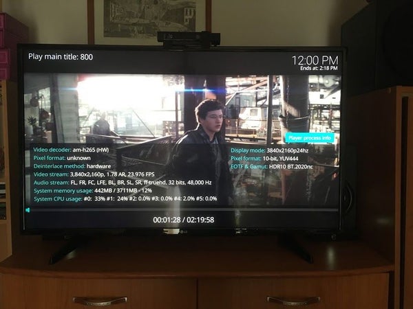
- It has 4k and HDR support, which the C2 was lacking
- USB 3.0 vs USB 2.0 ports. Due to the presence of these ports, it's more suitable to host several USB TV tuners, than the C2
- 4 GB RAM vs 2GB
- More powerful CPU, the ODROID-N2 is based on the new Amlogic S922 CPU, which means it’s capable of running plugins that require inputstream and must use software rendering (Netflix, for example) at full HD resolution, compared to 720p
- Has low power modes
- Has a modern 4.xx kernel compared to the older 3.14.x which was one of the major drawbacks of the C2. Due to the more modern kernel, it's more compatible with modern hardware, like USB tuners, game controllers, etc.
Step 1: Mechanical and Electrical Setup
As you've seen in my previous article, in order to have a media center that really looks like a factory built one, I've used an STB enclosure to host the components inside of it. However, over time I did many modifications to the setup and and that enclosure became broken. With this new board, I came to the conclusion that it's better to use a new enclosure. Since a picture’s worth a 1000 words, I've included some images that were taken while I was putting everything together. The steps were as follows:
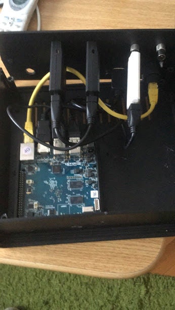
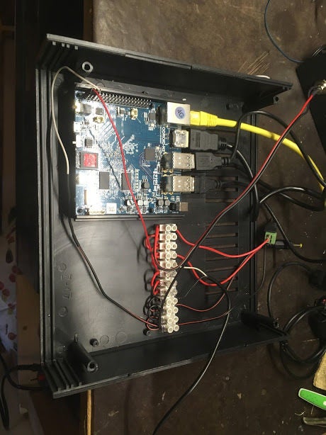
The bottom of the ODROID-N2 features 4 holes. I've used some plastic placeholders with screws in the end to mount it to the bottom of the plastic enclosure. It was important to be as close as possible to the front panel, as it has an IR receiver that can be useful at some point, even if I'm using a USB-based QWERTY remote (e.g., Airmouse type)
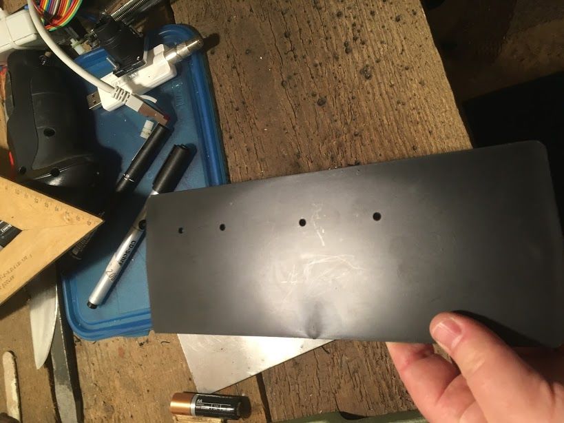
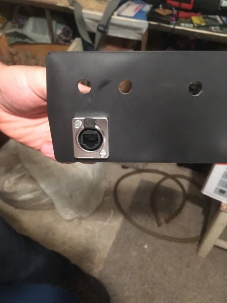
After, I drilled the holes on the bottom for the 4 tuners (2 Sundtek DVB-S2 , 1 DVB-C/T2 from Dvbsky, and a T330) and one Xbox ONE tuner (also for DVB-C) The Ethernet connector is a bit overkill, but I couldn’t find anything that was easily mountable (circular hole rather than rectangular one) : https://www.amazon.com/waterproof-connector-sockets-Socket-Ethernet/dp/B01HGMLOBI
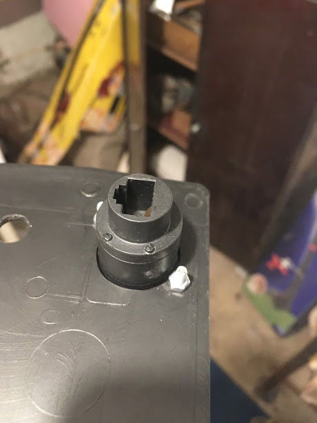
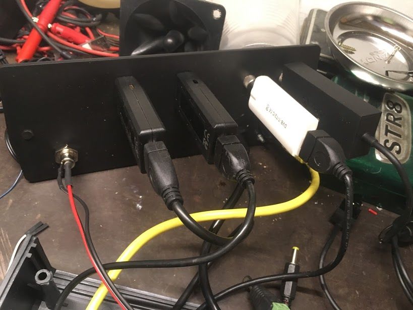
The HDMI cable was ordered from aliexpress. Basically it can be of any type, as long as it has some sort of possibility to attach it to the rear panel of the enclosure: https://www.aliexpress.com/item/Newest-30cm-50cm-60cm-1m-1-5m-V1-4-Gold-Plated-HDMI-Extension-Cable-Male-to/32822304686.html?spm=a2g0s.9042311.0.0.27424c4dQSVJ9O
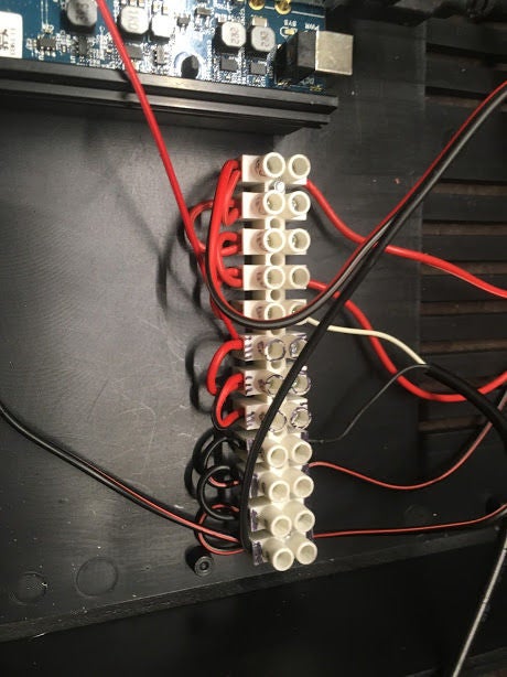
Power: Unlike the Raspberry Pi , the ODROID-N2 is supplied by 12V instead of 5V and has onboard voltage regulators to provide the 5V needed for the USB and other components. I did not find the maximum power it can handle, but I found no problem powering the 4 tuners and the VFD display module. On the 40-pin header, you have 5 pins for 5V output and also pins for 3.3V, if needed.
Power and Status LED: For the 12V and 5V power, I've used 2 LEDs, one was a UV LED, the other one a regular green. Note, that you will have to limit the current, otherwise you will damage the LED and/or the power supply. I've used 1.2K resistors in series, but based on what kind of illumination level you prefer, you might use a smaller one, but always calculate that the maximum current shall never exceed 20mA.
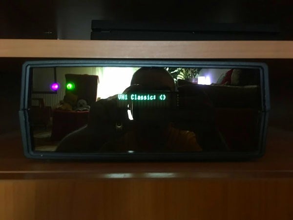
VFD: I've re-used the same VFD display similar to the one used in my previous article. It had an i2c backpack, which is enclosed in the white box that is visible in one of the pictures. You can connect it to the i2c port of the ODROID-N2, in the same was as it was connected to the C2 or the Raspberry Pi: 5V (pin 2 or 4), GND (pin 6), SDA (pin 3) and SCL (pin 5). See the GPIO header layout on Hardkernel's official Web page at https://www.hardkernel.com/blog-2/ODROID-n2/.
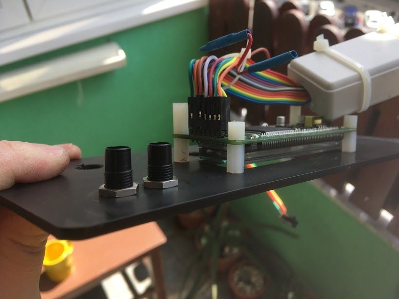
For the VFD and the 2 status LEDs, I had to cut the front panel. The enclosure I chose allowed it to have 2 front panels. I used the original plastic one to hold all of the components, and in front of it I used a glass, which I cut to the same size as the plastic one at the local shops that do such things.
Step 2: Software Setup
This part is a bit different than it was previously described in the article linked at the beginning of this article. For the Raspberry Pi we used the OSMC image that featured a full linux OS which allowed us to also install a build environment. Unfortunately, at the time of publication, there isn’t an image for the ODROID-C2 , nor the new ODROID-N2. Currently, the best support is done by the CoreELEC team, which is actually a fork from LibreELEC. This image has only a read-only system and Kodi is installed onto a separate partition, called /storage. This system is more immune to power loss and is harder to break, but also has some limitations: one must stick to the precompiled software which is provided via official or unofficial repositories. Regardless, one can find up-to-date versions of the software packages that we need: tvheadend, oscam, lcdproc and various addons for movies, live TV, and radio. First things first, however, before installing anything, an image must be burned to the SD card (or EMMC) and placed in its respective slot. The test image for the ODROID-N2 can be downloaded from https://discourse.coreelec.org/t/odroid-n2-test-builds/4560. Don't worry, that it's a test image! It works wonderfully, and even if there are some minor issues, it is very suitable for daily usage. Burn the image with Balena’s Etcher (https://www.balena.io/etcher/). If you did everything correctly, after placing the card into the slot, it should boot up nicely. To install the software services (tvheadend, oscam, lcdproc) use the CoreElec repository, Programs and Services folder. To configure the rest of the system, please refer to the previous article where I've covered every aspect in greater detail.
Step 3: Conclusion
The ODROID-N2 is the best board that is available to buy at this point. If speed is an important factor to you, then the ODROID-N2 is the best choice without any doubt.
Also, CoreELEC did a great job in supporting this board right from the beginning and I can only thank the people involved with it. This article has been adapted from the Instructable at https://www.instructables.com/id/Folow-UP-Advanced-Media-Center-With-ODROID-N2-and-/.
Be the first to comment